


Water Bath BBWA-3206
- Sea, Air, Door to Door Shipping
- 1 Year Warranty
- US & European Standards
- Microprocessor control with timing function
- Digital display
- Audible and visible alarm for over temperature
Specification
Features
| Capacity | 2.1 L x 3 |
| Electrical Requirement | 220 V 50 HZ |
| Power Consumption | 750 W |
| Temperature Range | RT+5-99°C |
| Temperature Stability | ±0.3°C |
| Display Resolution | 0.1 °C |
| Interior dimension | 150Wx125Dx110H mm |
| Exterior dimension | 490Wx245Dx310H mm |
| Timing Range | 1~999 min |
- Microprocessor control with timing function
- Digital display
- Audible and visible alarm for over temperature
Operating Manual for BBWA-3206
1. Scope of Application
2. Main Technical Parameters:
3. Structural Description
4. Usage
5. Operating methods
1. Power on
2. Check temperature control accuracy
3. Temperature and timing setting
4. Upper deviation alarm setting.
5. Methods to improve the accuracy of temperature control.
6. Sequence to pick up the functions of the instrument
7. Following table lists the function parameters
6. Precautions
7. Maintenance
8. Failure handling methods
Packing list
1. Scope of Application
It is used for precise temperature keeping and auxiliary heating by industrial and mining enterprises, colleges and universities, scientific research institutes and various labs, etc.2. Main Technical Parameters:
| Model | BBWA-3203 BBWA-3204 | BBWA-3201 | BBWA-3206 | BBWA-3202 | BBWA-3205 | BCHT-3302 BCHT-3301 |
| Mains voltage | 220-240V 50Hz/60Hz | |||||
| Power consumption(W) | 600/800 | 500 | 750 | 1000 | 1000 | |
| Range of temperature control | RT + 5 – 99C | RT +5-70C | ||||
| Temperature fluctuation | 0.5C | |||||
| Tracking alarm | 2C | |||||
| Dimension of the working room (MM) | 300 240 160 450 300 170 | 420 180 105 | 150 125 110 | 600 300 170 | ||
Table 1
3. Structural Description
The shell of electrothermal constant- temperature water tank is made of high quality steel plates; the surface is coated with plastic; internal liner, top cover and shelf are made of optimal corrosion-resistant stainless steel; on the bottom is a U-type electrical heating tube directly immersed into water, thus reducing largely heat energy loss; the interlayer adopts hard polyamine resin for insulation; the temperature control device on the right side has a power switch (or two switches: one for power supply and the other for water pump); instrument control panel has temperature-regulation knob, heating and tracking alarm indicator s and temperature digital display; the temperature control meter adopts micro-computer, thus making the temperature control precise and reliable. DKB-600B is specially designed with one low noise magnetic drive pump on the bottom of the right side of water tank, in order to guarantee the precision of temperature control of the water tank.4. Usage
1. Fill clean warm water into water tank up to 1/2 ~2/3 of the full height;2. Set the power switch to “ON” and then figures will appear on the temperature control instrument panel, indicating the power supply is on; if the water pump switch exists, set it to “ON” too;
When the measured temperature reaches the set temperature, the heating will be interrupted and the heating indicator will go out, and the temperature will become stable after 60 minutes of temperature keeping. If the temperature in the water tank exceeds the set temperature over 2 C (alarm temperature can be set arbitrarily), the alarm indicator of the temperature control instrument is on and the power of the heater will be automatically switched off in the meantime.
5. Operating methods
1. Power on
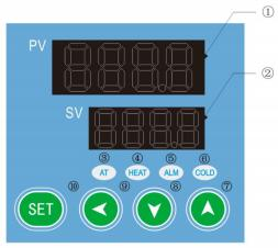
Figure 1
① (PV) display
* Display measured value
* Various prompts are displayed according to the status of the instrument.
② (SV) display
* Display set value
* Display various parameter values according to the status of the instrument
③AT (running indicator light): It lights up when the controller is working, flashes during auto-tuning, and goes off when it stops;
④ HEAT (heating indicator light): It lights up when there is heating output.
⑤ ALM (alarm indicator light): Lights up when there is an alarm output, and the buzzer sounds.
⑥ COLD (refrigeration indicator light): on when there is refrigeration output; (Note: this product has no COLD refrigeration function)
⑦ Used to adjust various parameter values or enter the auto-tuning state
⑧ Used to adjust the internal parameter value or enter the self-tuning state
⑨ Shift key: used to shift the set value, internal parameter and observe the timing running time;
⑩ Function keys:
* Setting value modification
* Recall of parameter symbols and confirmation of parameter modification.
2. Check temperature control accuracy
2. 1 Put a 0.5°C indexed mercury thermometer (or a digital thermometer with a resolution of 0. 1°C) into the product working room;The mercury probe of the thermometer should be in the geometric center of the effective space of the studio.
2.2 Choose a point within the temperature control range of the product and set the SV temperature control value. When the PV measurement value is equal to the set value, keep it at constant temperature ( 1 ~ 2) hours or so (depending on product specifications, the constant temperature time may vary) , Observe that the difference between the actual measured temperature value of the mercury thermometer and the measured value displayed by the temperature controller PV should be ≤±1.0℃ .
3. Temperature and timing setting
3. 1 In the working mode, press the key once, the PV screen will display
  characters, press
  or
or  key, to make the SV screen display the required temperature value; (refer to Appendix 2 for the process of recalling each function)
3.2 Press the key
again, the PV screen will display characters ,press or key, make the SV screen display the required time value; (refer to Appendix 2 for each function call process)3.2. 1 When the setting
is 0, the controller cancels the timing function and the controller runs all the time; when the ST setting is not 0, the controller has the timing function. When the running time of the controller is up, the SV screen displays "END", The buzzer buzzes, the controller stops working, press any key to mute the sound, press and key and at the same time for 4 seconds to restart.3.2.2 When the controller is in the working mode, just press the key
, the PV screen will display "TIME", and the SV screen will display the running time of the controller. Press the shift key again, and the controller will return to the working mode.3.3 In the timing state, press the key
again to return to the working mode and enter the working state.4. Upper deviation alarm setting.
The upper deviation setting is reasonable, which can protect the system from over-tolerance or out-of-control temperature control. It must be used when the product is working.4. 1 When the product leaves the factory, AL=10 ~ 15 is generally set, that is, the alarm temperature is: (SV+AL)C.
4.2 Press the "SET" key for about 4 seconds. When the PV screen displays the characters
 , release it and open the electronic lock before you can modify the relevant parameters.
Unlock procedure: Press and hold
 for 4 seconds. When the PV screen displays characters, use the key to change the value of the SV screen from "0" to "Unlock password=3" (user layer password), and then open the electronic lock (After 1 minute without any operation, the temperature controller will automatically return to working mode);
4.3 Press the key
a few times, when the PV screen displays characters , use the key to set a reasonable upper deviation value (AL);4.4 After over-temperature, the buzzer will alarm intermittently, and the over-temperature light
 will be on for a long time, press any key to silence;
4.5 When the temperature exceeds the AL value from the high temperature operating value set to the low temperature, it will also give an alarm, which is a normal situation, just press Mute.
5. Methods to improve the accuracy of temperature control.
5. 1 After the product has been used for a period of time, the temperature control accuracy should be checked according to the method 2.6, if it exceeds ± 1.0C, it can be corrected according to the following method:5. 1. 1 Enter the temperature controller parameter menu (see item 4.2)
5. 1.2 Opening the electronic lock (see item 4.3)
5. 1.3 Long press the "SET" key, go to the symbol
, enter LK=3 for accuracy correction, the correction method is as follows:Press PK = 4000 × (Measured value PV - standardable value)/ PV Measurements
After the formula is calculated, use the key
to modify on the basis of the original PK value at the factory (Note: One correction is inaccurate, and the correction can be repeated until it meets);6. Sequence to pick up the functions of the instrument
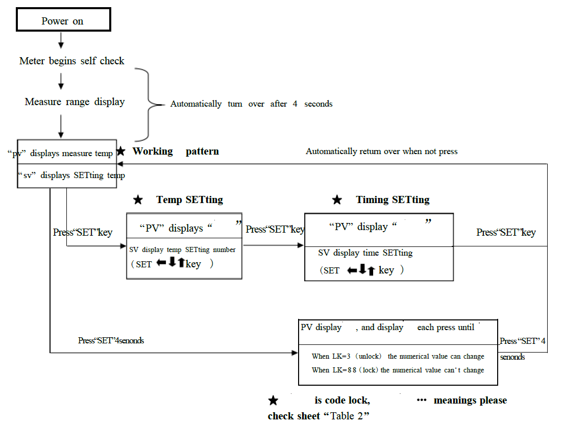
Figure 2
7. Following table lists the function parameters
| Symbol | Name | Setting range | Description | Factory set value |
| /tM | Setup of maxi temperature permissible by the instrument | 37.0-320.0 | Stop heating beyond maxi temperature and give alarm . | |
| /Po | Boot mode | 0~1 | ①when PO =0, after open the power, the controller in a stopped state, need to press the set key + increase key at the same time for more than 4 seconds to start running. ②when PO =1, after open the power, the controller will be running; | |
| /AL | Alarming setting | 0-Full Range 0.0-Full Range | When temperature is beyond SV+AL, the ALM indicator turns on. The buzzer sounds and the heating power turn off. | |
| /Pb | Zero point adjust (intersection) | - 100- 100 - 100.0- 100.0 | When the zero error comparatively smaller and the full point error comparatively larger, to update this value should be needed. Ordinary for pt100, updating this value is rarely needed | |
| /PK | Full point adjust(intercept) | - 1000- 1000 seconds | When the zero error comparatively larger and the full point error also comparatively larger, to update this value should be needed. PK=4000× (setting value-actual value)/actual value. For pt100 adjusting this value is need at first time. | |
| /LK | Password key | 0-255 | Input the password, the above parameters can be updated. |
Table 2
6. Precautions
1. The shell of the water tank shall be grounded effectively to guarantee the safe use.2. Before filling water, never press down the power switch so as to prevent the electrical heating tube from being burnt.
3. When any sound and light alarms are sent out from the water tank, please check whether the set temperature deviates from the normal range or not; if not, stop use and invite the professional personnel to inspect it or hand it over to our factory for repair.
4. Unless necessary, never disassemble the side plate of the temperature control unit so as to guarantee the safety
7. Maintenance
1. Always keep the internal and external of the water tank clean; do not wipe the shell with the chemical solution, which can cause chemical reaction, to prevent any chemical reaction.2. If the instrument is not to be used for a long time, cover it with a plastic thin film dust shroud and place it in a drying room so as to prevent the temperature control instrument from being moisturized and out of use.
3. The instrument is not suitable to be used in the environments of high voltage, heavy current, intense magnetic field or corrosive gases to prevent the instrument from being damaged by intervention and prevent the persons from the risks of the electroshock.
8. Failure handling methods
| Problems | Causes | Handling methods |
| 1. No supply | 1.The plug is not inserted well or the wire is disconnected. | 1. Insert the plug and connect the wire. |
| 2. Fuse is open. | 2. Replace the fuse. | |
| 2. The temperature in the cabinet does not increase. | 1. The set temperature is low. | 1. Adjust the set temperature. |
| 2. The electric heater does not work. | 2. Replace the electric heater. | |
| 3. The temperature control instrument does not work. | 3.Replace temperature control instrument. | |
| 4. The cyclic fan does not work. | 4. Replace the fan. | |
| 3.The set temperature has a big difference from the temperature in the cabinet. | 1.The temperature sensor does not work. | 1. Change temperature sensor. |
| 2.The fine tuning potentiometer for setting temperature is not adjusted well. | 2. Adjust the potentiometer. | |
| 4.The over-temperature alarm is abnormal. | 1. The set temperature is low. | 1. Adjust the set temperature. |
| 2.The temperature control instrument does not work. | 2. Replace the temperature control instrument. |
Table 3
Packing list
| No. | Type | Name | Unit | Qty. | Remarks |
| 1 | Document | Operating instructions | 1 | ||
| 2 | Document | Packing list | 1 | ||
| 3 | Spare part | Fuse core | 2 |
The articles in this list conform to those loaded in the box. Packing worker: No.2