Get Quote ▼
Concentrator BCON-105
Water Bath Concentrator
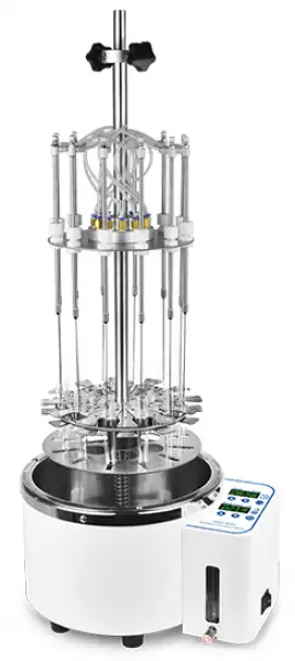
Water Bath Sample Concentrator is mainly used for the concentration or preparation of large quantities of samples (such as drug screening, hormone analysis, liquid phase, and sample preparation in mass spectrometry analysis). Working principle: By blowing nitrogen into the surface of the heated sample, the solvent in the sample is quickly evaporated and...
- Elegant appearance, with elevation operation panel, embedded flowmeter, waterproof button, safe and reliable.
- Good compatibility, suitable for test tubes (diameter 10 ~ 29mm), conical flask, centrifuge tube, the sample capacity of 1 ~ 50ml.
- Free up and down needle valve tube, independent adjustable needle valve, controls gas flow at each sample location
- Circular turntable structure, 360-degree rotation, convenient sample support into and out of the water bath, easy to operate.
Old SKU: BFA1CH1
 Get Quote
 Download Catalog
Specifications
| Model | BCON-105 |
| Temp. Control Range | R.T.+5°C~100°C |
| Temp. Setting Range | 5°C~100°C |
| Temp. Uniformity@60°C | ±1 °C |
| Temp. Display Accuracy | 0.1 °C |
| Heating Speed | <30min (40°C to 100°C) |
| Time Range | 1min~99h59min |
| Accommodates samples | 12 |
| Test tube range | Φ10~29mm/ Liquid volume1~50ml |
| Needle Plate Max. Lift Stroke | 200mm |
| as-in Joint Outer Diameter | Φ7mm |
| Maximum gas pressure | 0.2MPa |
| Maximum gas flow | 15L/min |
| Needle Length | 100mm |
| Inner dimension | Φ260x150mm |
| Voltage | AC 220V, 50/60Hz |
| Power | 1000W |
| Fuse | 250V, 8A, Φ5x20 |
| Dimensions | W.390 x D.300 xH.850mm |
| Net Weight | 9.5kgs |
Features
Elegant appearance, with elevation operation panel, embedded flowmeter, waterproof button, safe and reliable.
Good compatibility, suitable for test tubes (diameter 10 ~ 29mm), conical flask, centrifuge tube, the sample capacity of 1 ~ 50ml.
Free up and down needle valve tube, independent adjustable needle valve, controls gas flow at each sample location
Circular turntable structure, 360-degree rotation, convenient sample support into and out of the water bath, easy to operate.
12 position, each sample position are numbered, spring tube clamp fixed position.
LED real-time displays temperature and time, water bath temperature: RT +5 °C ~ 100 °C.
All use of stainless steel, all components are anti-corrosion and resistant to organic solvents.
When concentrated toxic solvents, the entire system can be placed in a fume hood.
Built-in level sensor, anti-dry protection.
Suitable for a variety of test tubes, so that the gas needle is aimed at the center of the test tube, and the experimental effect is greatly improved.
Applications
Pharmaceutical drug testing:Chinese medicine and drug testing.
Food and beverage: milk, wine, liquid beverages.
Biological analysis: serum, plasma, blood, urine.
Commodity inspection: test dioxin, croft etc.
Environmental analysis: drinking water, groundwater, polluted water, etc.
Pesticide analysis: vegetables, fruits, cereals, plant tissues, etc.
Food and beverage: milk, wine, liquid beverages.
Biological analysis: serum, plasma, blood, urine.
Commodity inspection: test dioxin, croft etc.
Environmental analysis: drinking water, groundwater, polluted water, etc.
Pesticide analysis: vegetables, fruits, cereals, plant tissues, etc.