


Vertical Laminar Airflow BLVR-305
- Sea, Air, Door to Door Shipping
- 1 Year Warranty
- US & European Standards
Compact design required for operations in an ultra clean, dust free environment. Ideal for laboratory applications where product protection is required. Small size saves precious laboratory space. Contains ultra thin filter including static pressure box without separator. Larger space permits working with laboratory equipments within the workspace.
- ETL certified, Satisfy North American market.
- With memory function in case of power-failure.
- Audio and visual alarm(Abnormal airflow velocity).
- Interlock function: UV Lamp and blower LED Lamp.
Specification
Features
Applications
| Type | The ETL certified vertical laminar flow |
| Airflow Velocity | Average of 80~99 fpm |
| HEPA Filter | One,99.995% efficiency at 0.3μm |
| Pre-Filter | Polyester fiber |
| Work Surface Height | 750~1010mm |
| Max Opening | 480mm |
| Working area Material | 304 stainless steel |
| Main Body Material | 1.2mm Cold-rolled steel with anti-bacteria powder coating. |
| Front Window Material | Motorized, 5mm toughened glass, anti-UV |
| Waterproof Sockets | One socket (Double type), America standard, Max.Power: 500W |
| UV Lamp | 30W x1 |
| LED Lamp | 14W x1 |
| Display | LCD Display |
| Illumination | ≥300lx |
| Noise | ≤68dB(A) |
| Standard Accessory | Manually height adjustable base stand; LED lamp; UV lamp; Wind speed sensor; Waterproof socket. |
| Internal Size | 1200Wx575Dx625H mm |
| External Size | 1300x700x(2090~2340)mm |
| Package Size | 1440Wx970Dx1560H mm |
| Gross Weight | 265kg |
| Consumption | 950W |
| Power Supply | 110V±10%V, 60HZ |
- ETL certified, Satisfy North American market.
- With memory function in case of power-failure.
- Audio and visual alarm(Abnormal airflow velocity).
- Interlock function: UV Lamp and blower LED Lamp.
Pharmaceutical, Pathology lab, Life science research, Plant tissue and cell culture
Operating Manual for BLVR-305
Preface
1.Unpacking, Installation and Debugging
1.1 Unpacking
1.2 Accessories Checking
1.3 Installation Conditions and Operating Environment
1.4 Installation
1.5 Inspection after Installation
2. User Instructions
2.1 Functions
2.2 Product Structure
2.3 Instructions for Operation.
2.4. Daily Maintenance
2.5 Replacement Parts List
2.6 Wiring Diagram
3. Trouble Shooting and Solution
3.1 Trouble Shooting
3.2 Replace the fuse
3.3 Replace fluorescent light
3.4 Replace the UV lamp
3.5 Label Description
4. Warranty
Preface
Thank you very much for purchasing our vertical laminar flow cabinet.Please read the “Operating Instructions” and “Warranty” carefully before operating this unit to assure proper operation. After reading these documents, be sure to store them securely together with the “Warranty” within reach for future reference.
 Warning: Before operating the unit, be sure to read carefully and fully understand important warnings in the operating instructions.
1.Unpacking, Installation and Debugging
Please firstly check if packing box is in good condition. If the packing box is damaged, please take photos.1.1 Unpacking
Choose proper tools and unpacking method as shown in the below picture.For wooden box:
1) Method 1 Necessary tools for unpacking: Electric drill with hexagon dead M8
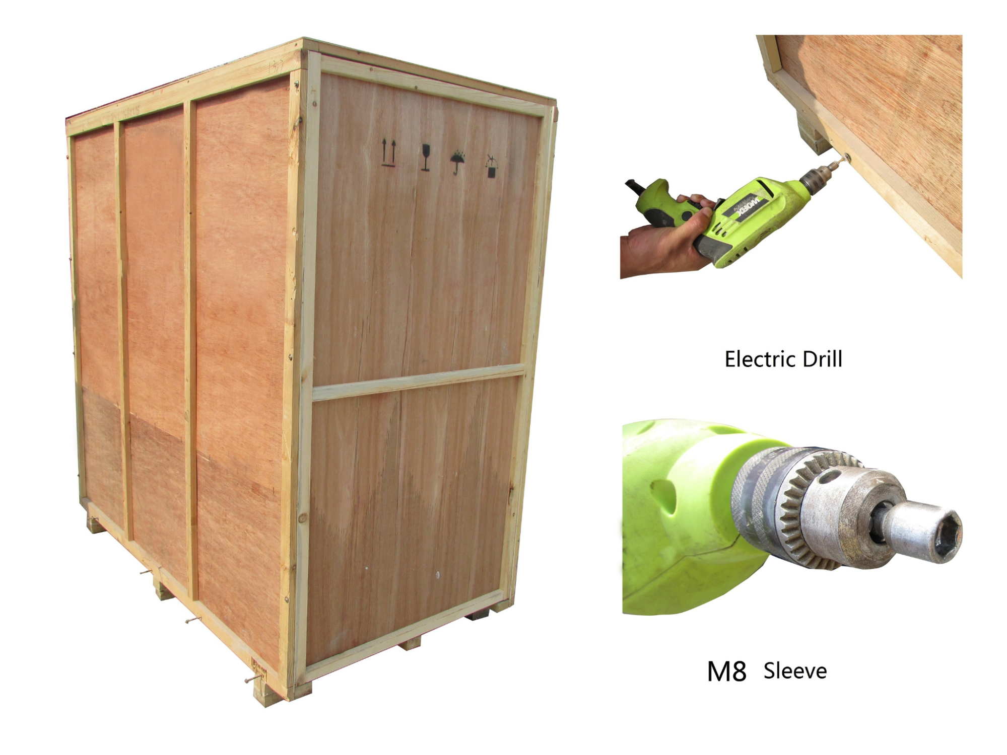
Figure 1
2) Method 2 Use M8 Wrench to unpack
The following diagram demonstrates quick unpacking procedures (Picture 3). Remove the screws as shown in the below diagram, then remove the wooden sheet to left of the wooden box.
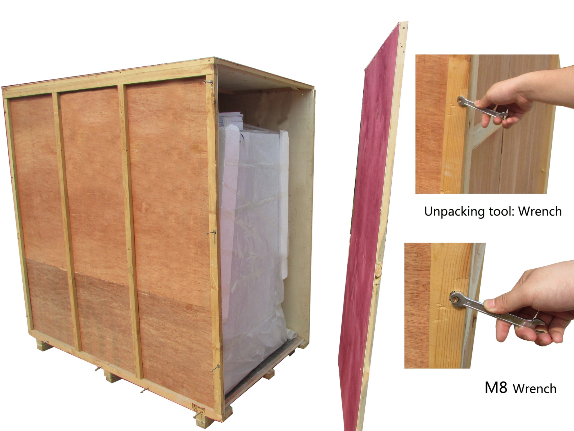
Figure 2
The following diagram demonstrates quick unpacking procedures (Picture 3). Remove the screws as shown in the below diagram, then remove the wooden sheet to left of the wooden box.
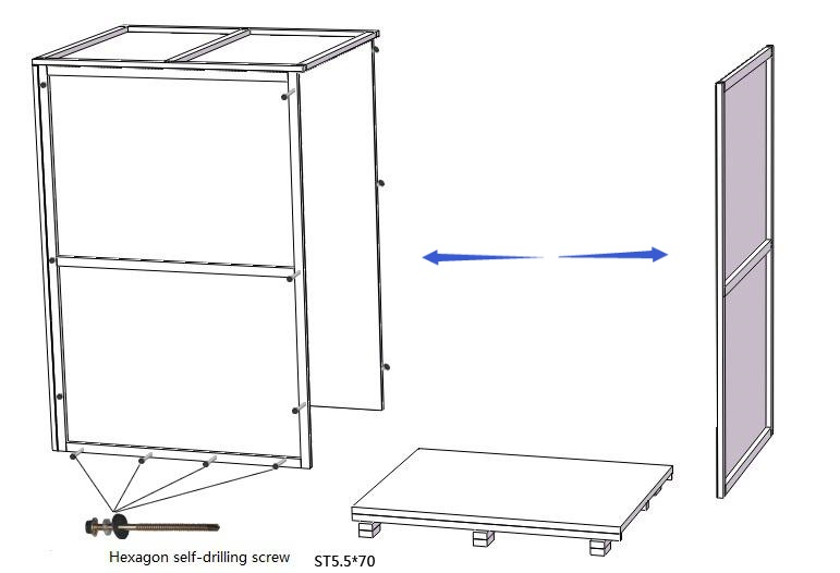
Figure 3
1.2 Accessories Checking
Refer to the packing list and check the accessories.BLVR-305 Packing list
| Items | Quantity | Position |
| Main body | 1unit | Wood package |
| Base stand | 1set | Paper package(Behind the cabinet) |
| UV Lamp(T6 30W) | 1pc | |
| Gas Tap SAN-3102 | 1pc | |
| Power Cord | 1pc | Bags(Behind the cabinet) |
| Fuse (10A) | 1pc | |
| Hexagon socket head cap screws M10*55+ flat washer 10+spring washer 10 | 3 sets | |
| Hexagon wrench | 1pc | |
| User Manual | 1pc | Envelope(Behind the cabinet) |
| Inspection report | 1 pc | |
| Certification of quality | 1 pc | |
| Warranty Card | 1 pc |
Table 1
BLVR-307 Packing list
| Items | Quantity | Position |
| Main body | 1unit | Wood package |
| Base stand | 1set | Paper package(Behind the cabinet) |
| UV Lamp(T6 30W) | 1pc | |
| Gas Tap SAN-3102 | 1pc | |
| Power Cord | 1pc | Bags(Behind the cabinet) |
| Fuse (10A) | 1pc | |
| Hexagon socket head cap screws M10*55+ flat washer 10+spring washer 10 | 3 sets | |
| Hexagon wrench | 1pc | |
| User Manual | 1pc | Envelope(Behind the cabinet) |
| Inspection report | 1pc | |
| Certification of quality | 1pc | |
| Warranty Card | 1pc |
Table 2
1.3 Installation Conditions and Operating Environment
Laminar flow cabinet shall be placed in a protection area, workspace can not be right opposite to the door or window, and away from the outlet of air conditioning, prevent from the ventilation system, air conditioning, door, window, and personnel movement caused by the airflow impact on Laminar flow cabinet.At least 300mm gap must be kept in the side and back side of the Laminar Air Flow for clean operating and for inspection.
Working environment:
(1) Only applicable for indoor operation
(2) Ambient temperature: 15° C ~35° C
(3) Relative Humidity: ≤75%
(4) Atmospheric pressure range: 70KPa~106KPa
(5) Electrical parameters: Adequate power supply to the laminar flow cabinet(See 2.1.4 Technical Parameters)
(6) Power supply need to be grounded; (Judging method: test the live wire and the neutral wire of the socket with multimeter. The voltage between live and ground should equal to the voltage of local electrical grid, and the voltage between neutral and ground should equal to 0. Otherwise the power supply is not grounded correctly)
1.4 Installation
a. Remove all the packing materialsb. Check the surface of main body to make sure there is no scratch, deformation or foreign bodies
c. Confirm the complement of accessories according to the packing list
d. Before removing the packing material, move the entire equipment to the place where it is going to be installed.
 The base stand will be packed at back of main body, please take it out before installation. DO NOT INVERT, DISASSEMBLE OR TILT THE CABINET during transportation.
e. Assemble the base stand with main body as shown in the picture.
Please assembled base stand refer to Figure 4
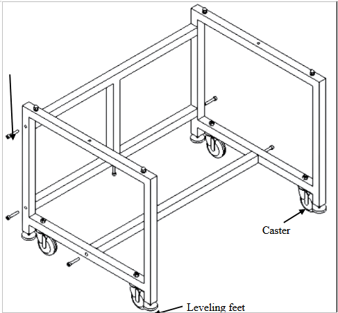
Figure 4
Removing Hexagon cylinder head bolt on both side lateral brace and T frame, the bottom of T frame, assemble referring to the picture, fasten the screw and Cap nut on the both side of base stand.
Foot height can be adjusted. Clockwise rotation of feet, when feet height is less than casters, the cabinet can be (or base stand) moved; anticlockwise rotation of feet, when feet height is greater than casters, then play a fixed role in preventing the cabinet (or base stand) from moving.
If you have any questions please contact engineers for commissioningf. connecting main body and base stand.
Please connect main body and base stand refer to Figure 5
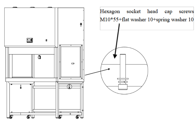
Figure 5
First, keep the main body above the base stand. (picture 5), then align the bolt of base stand. Mounting holes of the Main body at both sides, using Hexagon head bolt M10*55, flat washer 10, Spring washer 10 insert through base stand and the side panel and make them stable.
g. Pick up the gas (water) tap from accessory kit, first, unscrew the tap and nut, find the Mounting holes at the both side of cabinet glass. The Tap needs to be fixed as shown in the picture. The water mouth of the Tap should be inside the cabinet’s operating zone, refer Picture 6, The other end of the Tap which is having threading on the pipe should be inserted through the glass hole, the threaded pipe should be fastened with washer and nut outside the glass and need to be tightened with a wrench. Please refer the below picture to carry out the tap fixing to the cabinet. See figure 6 and 7.
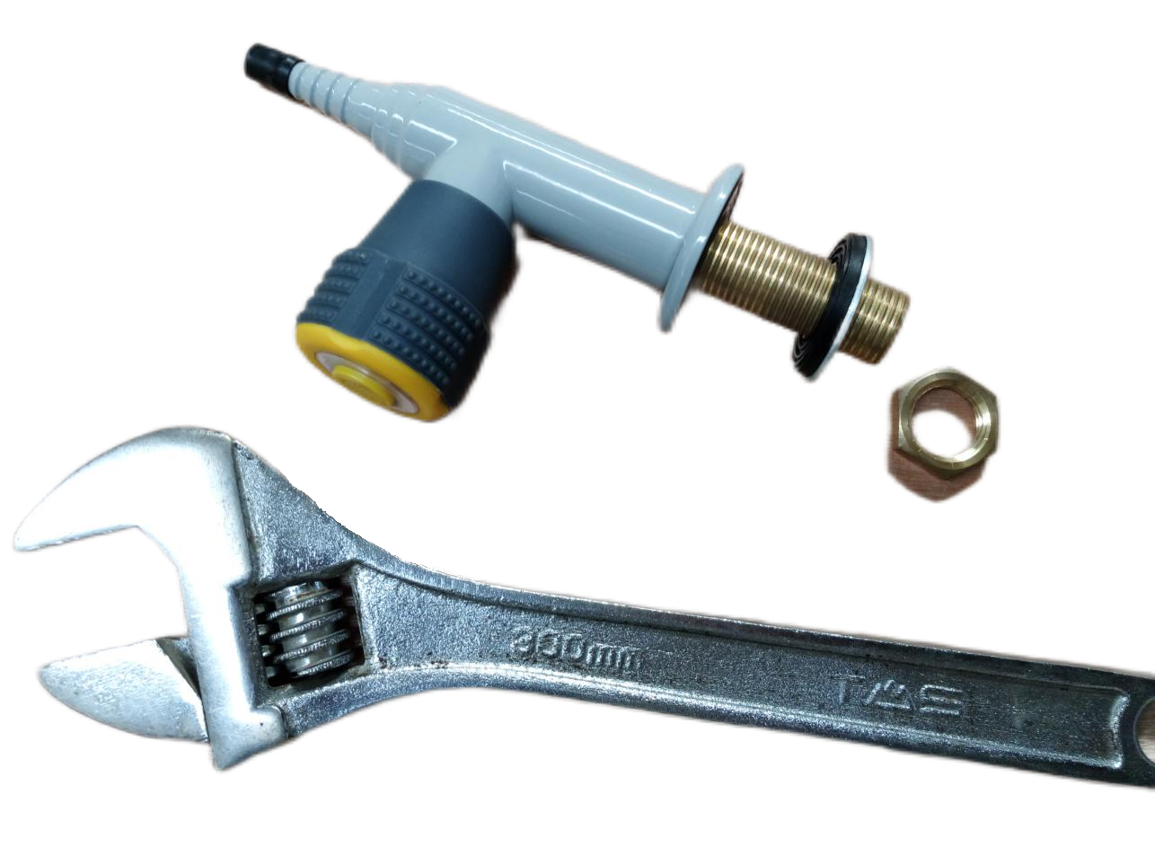
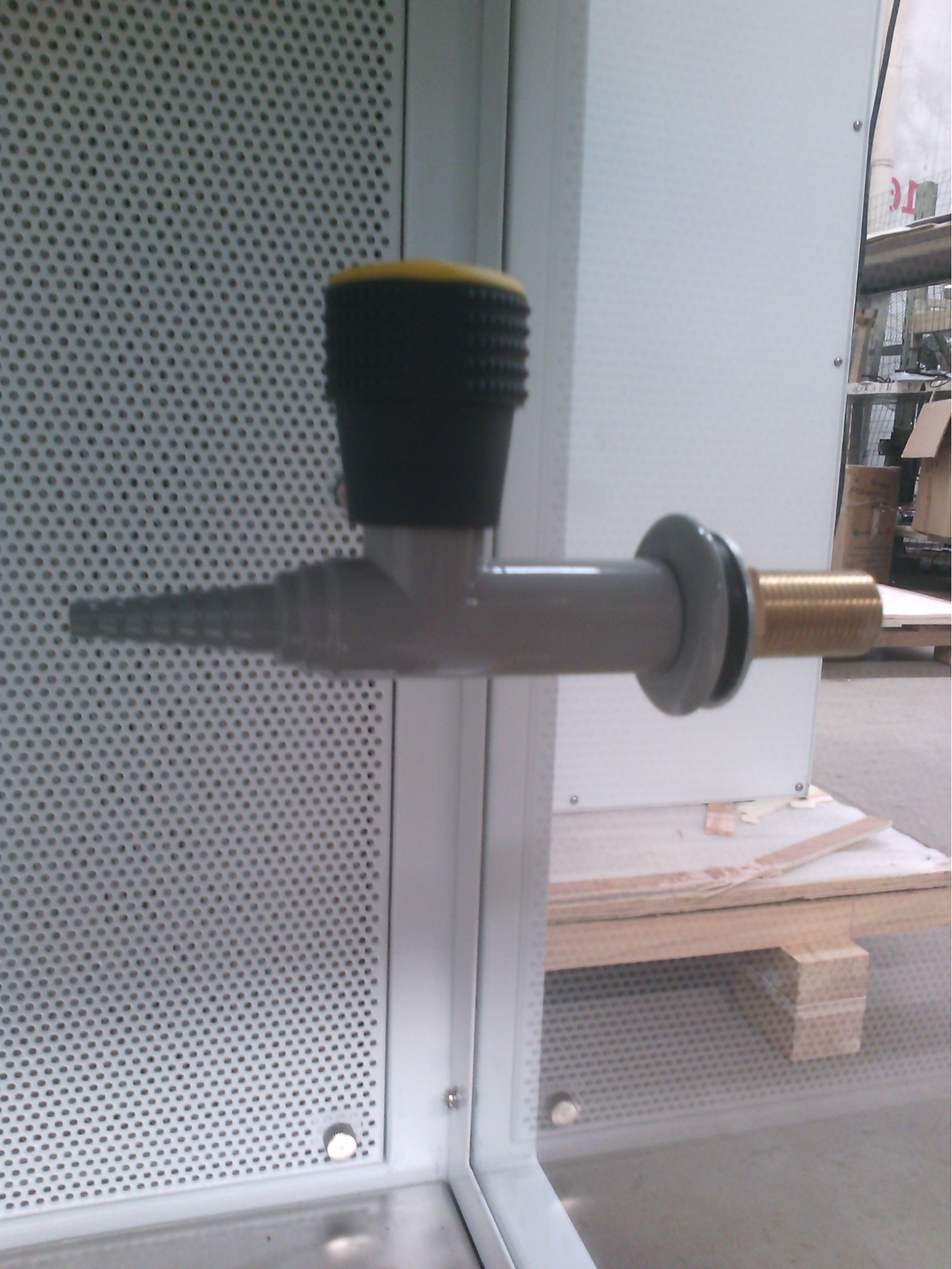
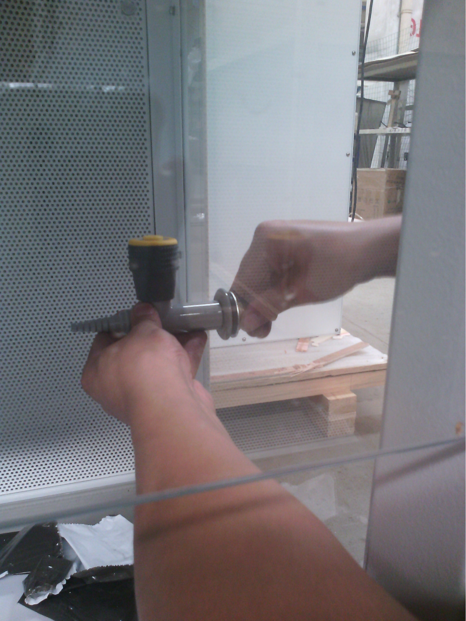
Figure 6
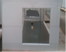
Figure 7
h. After the above steps, move cabinet to the right cabinet position slightly, remove the power cord, check the power cord is intact. See figure 7.
1.5 Inspection after Installation
First, make sure the voltage and frequency to be same as nameplate showing, and then check the follows items with power on:| Checking Items | Normal working status |
| Fan motor | Running normally |
| Fluorescent lamp | Lamp lights up after pressing button |
| UV Lamp | Lamp lights up after pressing button |
| Screen buttons | All buttons work effectively |
| Socket | Use multimeter to test voltage output after pressing the socket button |
Table 3
If you have any questions please contact engineers to commissioning, Debugging methods in the service manual.2. User Instructions
2.1 Functions
2.1.1 Product ConceptLaminar Flow Cabinet- LAF is used only for sample protection.
Laminar Flow Cabinet is a work bench or similar enclosure, which creates a particle-free working environment by taking air through a filtration system and exhausting it across a work surface in a laminar or unidirectional air stream. The laminar flow cabinet is enclosed on the sides and kept under constant positive pressure in order to prevent the infiltration of contaminated room air.
2.1.2 Works / airflow mode protection area
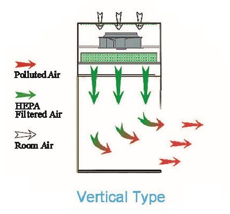
Figure 8
2.1.3 Protected objects
Laminar flow cabinet is to protect the experimental material, to create a local high cleanliness air environment, the main role is to ensure the accuracy of the operating area of the experiment, but for the environment and operators can’t afford protection.
2.1.4 Technical Parameters
| Model Parameters | BLVR-305 | BLVR-307 |
| External Size(W*D*H) | 1310*750*2040 mm | 1800*750*2040 mm |
| Working Zone Size(W*D*H) | 1200*645*610 mm | 1700*645*610 mm |
| Power Supply AC | 220V±10% 110V±10% | |
| Frequency | 50 Hz 60Hz | |
| Consumption | 400W | 450 W |
| Airflow velocity | 0.3~0.5m/s | |
| UV Lamp Consumption | 30W*1 | 40W*1 |
| Fluorescent lamp | 12W(LED)*1 | 16W(LED)*1 |
| HEAP Filter | 99.999%efficiency at 0.3μm | |
| Noise | <65dB | |
Table 4
Note: Biolab reserves the right to make changes in future product design, without reservation and without notification to its users.
1) Vibration amplitude
The net vibration amplitude between frequency 10Hz and 10KHz is no more than 5μm(rms).
2) Illumination
The average illumination is more than 350 lux.
3) Electrical properties
The cabinet would not breakdown in 5s when the voltage increases by 1390V (AC) within 5s. Grounding resistance ≤0.1Ω.
2.2 Product Structure
2.1 Structural Composition of BLVR-305/ BLVR-307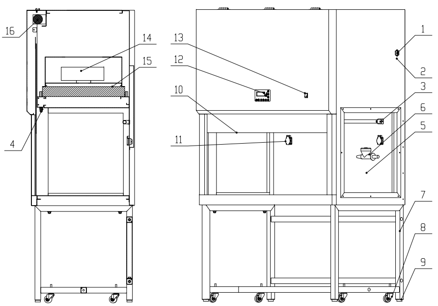
Figure 9
| 1 | Power Socket | 9 | Leveling feet |
| 2 | Ground terminal | 10 | Front window |
| 3 | UV Lamp | 11 | Water-proof socket |
| 4 | LED lighting lamp | 12 | Control panel |
| 5 | Side glass window | 13 | Power switch |
| 6 | Gas Tap | 14 | Zero line fuse |
| 7 | Base Stand | 15 | HEPA filter |
| 8 | Caster | 16 | Tubular motor |
Table 5
2.2.2 Structure Inntroduction
1) Driving system of front window
Driving system consists of tubular motor, front window, hauling mechanism and limit switch.
2) Air filtration system
Air filtration system is the core system of laminar flow cabinet. It consists of blower and HEPA filter system. The main function of air filtration system is to transfer filtered air to work area, ensure airflow velocity, and keep Class 100 cleanness of work area.
3) UV lamp
The UV lamp located at the top of the work zone effectively disinfects the entire work zone by emitting a wavelength of 253.7nm
4) Fluorescent light
The laminar flow cabinet is equipped with LED light, which ensures the standard requirement of average illumination is met.
5) Control Panel
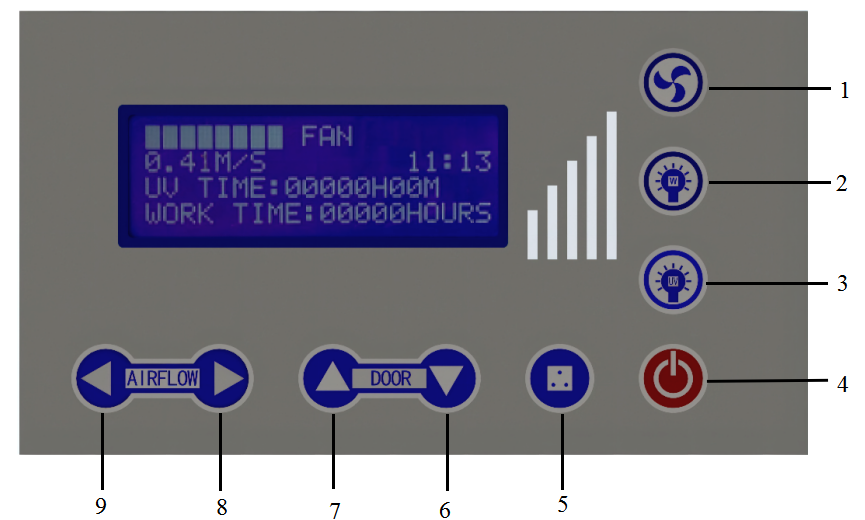
Figure 10
| 1 | Blower | 5 | Socket |
| 2 | LED lamp | 6 | Glass window up |
| 3 | UV lamp | 7 | Glass window down |
| 4 | Power | 8 | Air volume decreases |
| 9 | Air volume increase | ||
Table 6
a. Gear display
Working wind speed can be known by gear display.
b. Soft touch button
 | Power button | Press the power button, the equipment will switch between suspension mode and working mode. |
 | Fan button | To control fan working status. Fan has a memory function, that is, at the time of starting up the fan, it can display the gear when it was shut down last time, by which, there is no need to adjust the fan gear every time. (Note: It will not work when front window is fully closed) |
 | Lighting button | To control LED lamp. |
 | UV lamp button | To control UV lamp (UV lamp, fan, LED lamp and front window interlock; it won’t work when LED lamp, fan and front window open ) closed). |
 | Socket button | To control socket power status. |
 | Function setting debugging button | Press the glass Down button, glass window will fall down. Each time you press, the buzzer will sound; hold down this button, the glass window will continue to decline; release the button, the glass window will stop declining. |
| Function setting debugging button | Press glass UP button, glass window will raise. Each time you press, the buzzer will sound ; hold down this button, glass window will continue to raise; release the button, the glass window will stop raising. |
 | Air flow adjustment button | To control fan speed increase. When fan is working, if ▊number is less than 8, each time you press, wind speed can increase a gear, and the buzzer rings once, until▊▊▊▊▊▊▊▊appears. Press this button when you use the UV lamp, UV lamp timing time increases, and the maximum time is 90 minutes, set time can be remembered. |
| Air flow adjustment button | To control fan speed down. When fan is working, if ▊number is more than 1, each time you press, wind speed can reduce a gear, and the buzzer rings once, until one ▊appears. Press this button when you use the UV lamp, UV lamp timing time decreases, and the minimum time is 10 minutes, set time can be remembered. |
Table 7
The main operation of the device can be carried out by touching button.LCD display: When powered on, from top to bottom is ▊▊▊▊▊▊▊▊▊FAN, It indicates the strength of blower wind speed; Shown below is the current state of the Winds; The right of the display is time; UV TIME, UV lamp working time; WORK TIME: HEPA filter working time.
Clock Adjustment: In standby mode, press light button continuously to enter clock setting mode after a buzzer alarm. Firstly, minute position is flashing, press UP and DOWN to adjust to present time. Then press the blower button switching to hour position and adjust to present time. After that, press the light button again, data will be saved after a buzzer alarm.
UV lamp timing: In standby mode, when the front window is lowered to a minimum, please press UV lamp control button
 , then the UV lamp is opened. After opening the UV lamp, the display will show the current status of the UV lamp timing: By pressing blower speed down button
  , the setting time will be reduced one minute each time; by pressing blower speed up button
  , the setting time will get be increased one minute each time. You can set the time as needed (UV lamp timing range is 0-90 min, and the max factory setting is 90 min)
6) Motorized glass door control
The front window is motorized, with the touch of a button can be controlled freely.
7)Water proof socket
Waterproof socket is arranged in the operating area, to within the operating area of the power supply equipment and in the lighting lamp installing the front side plate(figure 1) and when need to use a socket, open the equipment power supply, press the socket button (figure 10), open the waterproof socket cover, access to electricity source plug.
(1) Please make sure the total load of sockets should be ≤ 500W;(2) Waterproof socket is waterproof only when the front cover is down. When the front cover is opened, the socket can not be considered waterproof socket.
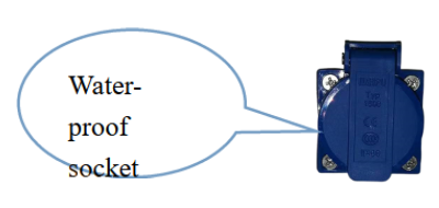
Figure 11
8) Fuse
The equipment is equipped with main power fuse, They are located near the power cord’s outlet. Fuse label is corresponding to the relevant specifications as shown in Picture 3.5.1. The replacement of fuse is showed in Picture 3.2.
9) Structure
a) Cabinet body is built up of 1.2mm cold-rolled steel with anti-powder coating. Strong and steady.
b) Work table is fully made up of 304 stainless steel which looks beautiful and has corrosion resistance performance.
c) Base stand is made up of cold-rolled steel with anti-powder coating.
d) Soft touch type control panel, beautiful appearance and easy handling
2.3 Instructions for Operation.
2.3.1 Normal Operation Notice(1) Make sure input voltage is correct and stable. The rated load of main power socket should be higher than cabinet consumption. Plug must be well grounded.
(2) Moving principles of different samples inside cabinet: When two or more samples need to be moved, be sure that low-polluting samples move to high-polluting samples. Movement of items should also follow the principles of moving slowly and stably.
(3) The weight of items placed in the cabinet should not be more than 23Kg/25×25cm2;
(4) Avoid vibration: avoid using vibration equipment (e.g. centrifuge, vortex oscillator, etc.) inside the cabinet. The contamination might drop from the HEPA filter thus making the operation area cleanliness lower.
(5) No flame: An open flame would create turbulence which disrupts the pattern of HEPA-filtered air supplied to the work surface. If sterilization is required during the experiment, infrared sterilizer is highly recommended.
(6) HEPA filter life: With the usage time increasing, dust and bacteria accumulate within the HEPA filter, filter resistance is getting bigger, when it reaches the maximum point, the speed requirements can’t be met then please contact BIOLAB service department to get a new one. The used filter should be processed as medical waste.
(7) Please do NOT remove or loose the screws of those parts. To contact service personnel for special technical requirements.
(8) The maximum storage period is one year. If the period is more than one year, performance test should be done
Serious declaration: we will take no responsibility for risks caused by improper operation and man-made damages!2.3.2 Operation Process
a. Connect to a suitable power supply
b. Press relevant function keys (related keys, function and operation please refer to 2.2.2 description); check the function keys and the operation results are consistent, and according to the above technical parameters table to test whether the blower normal starts and wind speed is up to the standard requirements, fluorescent lamp and UV lamp is normal work.
UV lamp function could only be selected when front window is fully closed.c. The cabinet should be sterilized by UV lamp for at least 30 minutes with the window fully closed before any experiment.
(1) For safety of eyes and skin, people should leave the room during the UV sterilization.(2) UV lamp should be checked regularly. It should be replaced when either the total working time reaches 600 hours or the intensity is lower than the requirement.
d. Please move up the front window at the suitable height above the work table and turn on the fan. Make sure the experiment should be started after fan working for at least 30 minutes.
For operating safety, please place the experiment materials inside the cabinet before experiment start.After finishing the experiment, please fully close the front window and make sure to sterilize the cabinet by UV lamp for 30 minutes before turning off the cabinet.
2.4. Daily Maintenance
Preparations before maintenance: removal of items in the equipmentPreparation of goods: cotton or towel, concentrated soap, hot water, water, medical alcohol or other disinfectants, etc.
2.4.1 Clean the cabinet surface
Clean the surface of working zone
Wipe the entire surface with a soft cotton cloth which has been soaked with concentrated liquid soap. Afterwards, wipe off the foam with another cotton cloth or towel which has been soaked with clean hot/warm water. At the end, wipe the entire surface with a dry cotton cloth or towel rapidly.
For the contaminated or dirty work surface and sump, use 70% rubbing alcohol or other disinfectant to wipe.
Disinfectants used for wiping should not damage the 304 stainless steel.2.4.2 Clean the external surface and front window
Use a piece of soft cotton cloth or towel with non-abrasive household cleanser to wipe the surface.
2.4.3 Overall maintenance period
The recommended interval period for comprehensive maintenance is either one year or 1000 working hours.
2.4.4 Maintenance methods
1) Daily or weekly maintenance
a. Disinfect and clean the operating area;
b. Clean the external surface and front window around the operating area (Refer to 2.4.1 );
c. Check the various functions of equipment (Refer to 2.4.2);
d. Record down the maintenance result.
2) Monthly maintenance
a. Clean external surface and front window (Refer to 2.4.2 );
b. Use towel with 70% rubbing alcohol or 1:100 dilution of household bleach(0.05% sodium hypochlorite) to wipe the working table, the inner face of front window and the inner wall surface of the working area(exclude the top wind grid). Use another towel with sterile water to wipe those area to erase the remain of chlorine;
c. Check the various functions of the cabinet;
d. Record down the maintenance result.
3) Annual maintenance
a. Check the two lifting belt of the front window tubular motor, make sure both of them are well connected to the motor with same tightness.
b. Check the UV lamp and LED light.
c. Apply for overall performance test of the cabinet annually to ensure that the safety meets requirements. User is responsible for testing costs.
d. Record down the maintenance result.
When doing maintenance, please pay attention to cut off the power, so as to avoid electric shock!2.4.5 Storage conditions
Laminar flow cabinet should be stored in a warehouse with relative humidity no more than 75% and temperature lower than 40°C. The warehouse should have good ventilation performance without acid, alkali or other corrosive gases. Storage period shall not exceed one year. Safety cabinet stored for more than one year needs to be unpacked and checked before selling and using. Only the tested and qualified safety cabinet could be sold.
2.5 Replacement Parts List
BLVR-305 replacement parts list| Number | Nam e | Specification |
| BS-01 | Fuse | Φ5*20, 10A |
| BS-02 | Lamp holder T8 | LG13-01A |
| BS-03 | UV Lamp | T6 30W |
| BS-04 | LED holder T5 | T5 12W |
| BS-05 | UV lamp ballast | 1*TL8-30W |
| BS-06 | HEPA filter | 1223*570*69mm |
| BS-07 | Fan | FH320A, 3C certified |
| BS-08 | Control panel | LCD control panel |
| BS-09 | Front window glass | 1223*640*5mm |
| BS-10 | Side window glass 1 | 575*540.5*5mm(has hole) |
| BS-11 | Side window glass 2 | 575*540.5*5mm |
| BS-12 | Single wall gas tap | SAN-3102 |
Table 8
BLVR-307 replacement parts list
| Number | Name | Specification |
| BT-01 | Fuse | Φ5*20, 10A |
| BT-02 | Lamp holder T8 | LG13-01A |
| BT-03 | UV Lamp | T6 30W |
| BT-04 | LED holder T5 | T5 16W |
| BT-05 | UV lamp ballast | 1*TL8-30W |
| BT-06 | HEPA filter | 1690*570*69mm |
| BT-07 | Fan | FH320A, 3C certified |
| BT-08 | Control panel | LCD control panel |
| BT-09 | Front window glass | 1723*640*5mm |
| BT-10 | Side window glass 1 | 575*540.5*5mm(has hole) |
| BT-11 | Side window glass 2 | 575*540.5*5mm |
| BT-12 | Single wall gas tap | SAN-3102 |
Table 9
2.6 Wiring Diagram
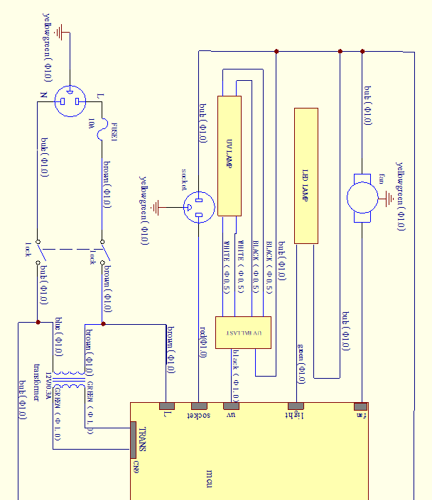
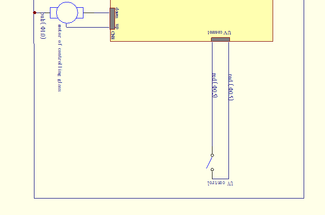
Figure 12
3. Trouble Shooting and Solution
3.1 Trouble Shooting
Please confirm that the power is well connected, the cord is in good condition(without any damage) and the power lock is unlocked before trouble shooting the following problems.| Faults | Check parts | Measures |
| Fluorescent lamp doesn’t work | LED holder plug | Connect the plug and holder tightly |
| LED holder | Change it | |
| Circuit | Check circuit | |
| Control panel | Change it | |
| UV lamp doesn’t work | Interlock | Check the fluorescent lamp and the blower is open or not. |
| Lamp holder | Tube and lamp holder is connected securely. | |
| Circuit | Check circuit | |
| Ballast | Change it | |
| UV lamp | Change it | |
| Micro Switch | Check if Micro Switch is broken | |
| Control panel | Change it | |
| Button doesn’t work | Control panel | Make sure the power connects well and the fuse is well |
| Check if the button is broken | ||
| Make sure the connecting wire is connected well | ||
| Change control panel | ||
| Blower doesn’t work | Micro Switch | Check if Micro Switch is broken or works fine |
| Blower | If blower is broken, change it | |
| Circuit | Check circuit | |
| Control panel | Change it | |
| No electricity in equipment | Power supply | Check power supply connects well |
| Power wire | Check whether power wire has obvious damage | |
| Fuse | Check if the fuse is good | |
| Transformer | Check whether the transformer works normally | |
| Control panel | Change it | |
| Display doesn’t work | Connection winding displacement | Connection winding displacement |
| Display screen | Display screen | |
| Control panel | Change it |
NOTES(1) The above trouble shooting methods should be done by qualified electricians under safe conditions(cut off power supply). Other components should not be removed. Risk caused by failing to follow those instructions would be responsible by user.
(2) Please contact Biolab technical department if a failure could not be traced or solved. Do NOT repair the equipment without a qualified electrician.
(3) The trouble shooting and repair of this equipment only could be undertaken by trained and recognized technicians.
(4) Please contact BIOLAB or our agent technical department or agent to order required component or part. The model number and the serial number of purchased cabinet need to be indicated.
3.2 Replace the fuse
Fuse of waterproof socket is located at the right side of the cabinet. For replacing the fuse, turn off the power and disconnect the plug. Use a flathead screwdriver to unscrew the fuse holder. Replace the fuse inside the fuse holder and put it on back.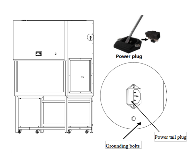
Figure 13
Take out the fuse tube base with a flat screwdriver. Then can replace and check the fuse.
3.3 Replace fluorescent light
When the fluorescent light needs to be changed, turn off the power. Then remove the LED stand, unplug the right side, After replacing a new LED stand, inserted into the inclined slot.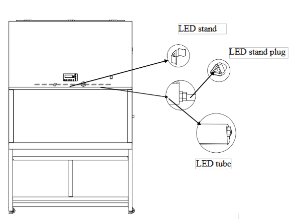
Figure 14
3.4 Replace the UV lamp
The UV lamp tube should change regularly, such as every 600 hours. For replacing the lamp tube, turn off the power and disconnect the plug. Rotate the tube for 90° to remove it and then install a new UV lamp tube by rotating in reverse direction. After replacing the UV lamp, the accumulated using time should be reset to zero by pressing and holding the UV button for 5 seconds. A buzz alarm would occur to indicate the reset.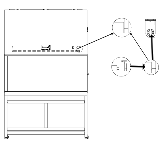
Figure 15
Put hands at 2 ends of the lamp, clockwise/anticlockwise screw 90°the lamp to take it down. Then put aside it carefully. Put a new one into the holder, clockwise/anticlockwise screw 90°. Then turn on the power and test it.
Picture 15
3.5 Label Description
3.5.1 Fuse label
Figure 16
Note:10A power fuse label
3.5.2 Ground label
Figure 17
4. Warranty
1) Warranty is 12 months from EX-factory date (excluding consumable accessories: UV lamp, fluorescent lamp and fuse).2) Biolab would not be liable for any repair of damage caused by improper operation.
3) If the warranty has been expired, Biolab would still responsible for repair with relative charges.
4) Life time of laminar flow cabinet is 8 years from production date on the label.
5) Biolab would provide equipment drawings and necessary technical data for maintenance companies or personnel trained by Biolab engineers.
Warranty declaration: One-year Warranty, Life-long Maintenance.