Get Quote ▼
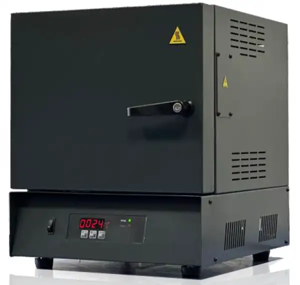
Muffle Box Furnace BFMF-1100-30A
- •Bestprice-performanceration
- •Dualshellhousingforlow Outer surface temperature
- •Idealforashingoffood, plasticandotherorganic materials
- •Reliable
- •1yearwarrantyexcept heating elements and thermocouples. They are super economic models with optimum insulation properties and basic control options.
- •Economical, lightweight and reliable.
- • Ideal for basic ashing, burning and similar processes.
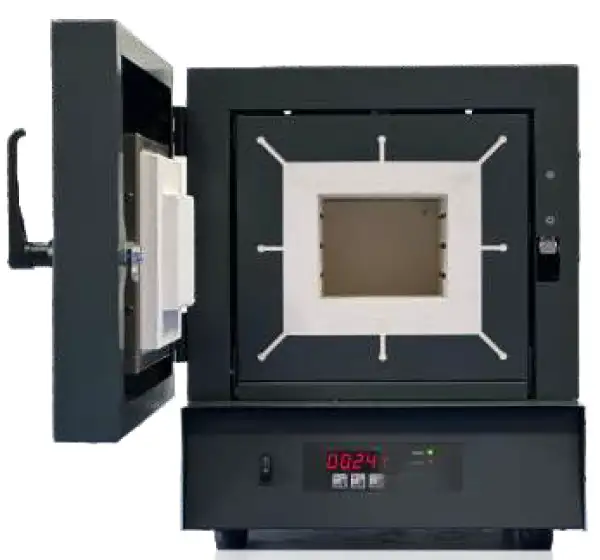
- • Bottom, side and top walls made of light firebrick.
 Get Quote
Specifications
| Model | BFMF-1100-30A |
| Maximum Working Temperature | 1100 °C |
| Volume | 30L |
| Continuous Working Temperature (°C) | 1050°C |
| Inner Chamber Dimensions (mm) WxHxD | 240x200x345 |
| Product Outer Dimensions (mm) WxHxD | 494x565x590 |
| Net Weight (kg) | 38 |
| Power (W) | 3000 |
| Max. Current (A) | 14 |
| Electrical Connection | 1 Phase |
| Heating Element | Fe-Cr-Al |
| Thermocouple Type | K Type |
| Heating Element Placement | Embedded into brick walls |
| Inner Insulation Material | Ceramic Fibre Board or Insulating Fire Brick |
| Front Face Insulation Material | Ceramic Fibre Board |
| Door Insulation Material | Ceramic Fibre Board |
| Housing Material | Steel Sheet |
| Housing Coating | Epoxy powder coating |
| Chimney | None or Basic Tube, Chimney on top |
| Lockable Door Handle | Sidewards |
| Gross Dimensions (mm) WxHxD | 595x785x680 |
| Gross Weight (kg) | 59 |
| Software | Primary Px |
| Software based PID Control | YES |
| Display | 7 Segment |
| Heating Program with | 4 steps |
| Custom Preset Program | 2 |
| Heating Rate °C/min. | 5-25 |
| Date & Time | NO |
| Auto Start at Certain Date | NO |
| Show Remaining Waiting Time | NO |
| Skip the Waiting Step | NO |
| Temperature Calibration via Menu (±10°C) | NO |
| Sound Warnings at Step Changes | NO |
| Sound Warning at the End of the Program | YES |
| Total Working Hour Counter | NO |
| Calculator for Average Working Temperature | NO |
| Instantaneous Energy Consumption Indicator | NO |
| Over Heating Cut Off | YES |
| Open Door Sensor | NO |
| PC Connection Kit | NO |
| Warranty Period | 2 Years |
| Note | * Only 5th memory supports 32 levels **Independent for each level |
Features
•Dualshellhousingforlow Outer surface temperature
•Idealforashingoffood, plasticandotherorganic materials
•Reliable
•1yearwarrantyexcept heating elements and thermocouples. They are super economic models with optimum insulation properties and basic control options.
•Economical, lightweight and reliable.
• Ideal for basic ashing, burning and similar processes.
• Bottom, side and top walls made of light firebrick.
• Lockable door handle.
• Thanks to SSR driven duty cycle control algorithm, accurate temperature control.
• Easy to use.
Operating Manuals
 Download Manual (PDF)
1. DEFINITION
2. SAFETY
2.1 PROPER OPERATION
2.2 OPERATION IN SAFE CONDITIONS
3. FIRST HEATING
4. DISPLAY & MENU
4.1 START & STOP FOR HEATING
4.2 FOLLOWING, ENTERING & CHANGING PARAMETERS
4.3 MENU
4.4 BUTTONS
APPENDIX-1 Technical Specifications
APPENDIX-2 Control Unit Features
1. DEFINITION
Series are laboratory type heating furnaces. Heating is performed up to 1100°C. This temperature is maximum temperature; continuous working temperature & adjustable temperature is 1050°C on these furnaces.
2. SAFETY
Heating furnace may harm operating people or surrounding any other materials, unless this operating manual is applied during operating process.
Thus;
-Periodical maintenance should be applied.
-Cautions against accidents should be main concern of operators.
-All operating directives, warnings and recommendations in this operating manual have to be followed and applied carefully.
Unless operating directives, warnings and recommendations in this operating manual are followed and applied, company Biolab is not dedicated for the accidents that may occur.
2.1 PROPER OPERATION
Muffle Furnace can reach up to 1100°C. Thus materials that can stand up to 1100°C can be heated in the chamber. The conditions that should be considered during operating or the points which are the reason no to start operational process are as follows,
• Furnace is not started, if there is any living thing in the chamber.
• Any burning, flammable, exploding, poisoning, (Benzene, LPG, Acetylene etc.) material that may harm when it is heated etc. is not stored or put inside the chamber. These types of materials should be kept away from the furnace.
• Outside case of the furnace may be hot. It should be considered. Especially, when the furnace is heated above 1000°C and if it is kept above this temperature 30 minutes or more, you shouldn't touch to outside case/surfaces without using gloves.
• Instant high heat should be considered, when the front door is open.
• Electronic and/or Electrical components may create induction current or magnetic field. It may harm any electronic equipment surrounding the furnace. Especially cardiac pacemaker users should be away from the furnace.
• It should not be operated in closed environments such as in cupboard etc.
• Furnace should not be operated by multi plug in tools. It should be operated by stationary plugs which are mounted on the wall.
• Electricity plug have to be grounded.
 DANGER
Explosive, flammable, burning, poisonous materials, don't heat up.
 WARNING
Hot Surface
DANGER
Instant high temperature, when the front door is opened.
2.2 OPERATION IN SAFE CONDITIONS
"Contribute in to SAFETY CAUTIONS in the work shop."
Please obey to safety rules. Please inform responsible person, as soon as you notice any abnormal condition for the furnace.


Please use protective glass or protective gloves, when you are working.
Don't let non-permitted person contact to any electrically alive parts. Possible electrically alive parts should be processed by responsible persons and by experts. Cables should be protected against/away from any heat, oil, oily material, sharp tools and materials. Cables should be kept away from furnace surface. Any cable may kill, if any parts of the cable are broken / damaged or cable touches on to the furnace surface. Any broken cable should be replaced by the new one.
- Danger of life due to electrical shock.
DANGER
- Danger of life due to electrical shock.
DANGER
To touch in to the electrically alive parts may kill, if cable is broken or damaged. Be aware of the environmental affects: Don't use electrical tools, equipment and machines in wet circumstances. Keep light intensity enough to make easier for the working people. Plug off the machine, before any cleaning, repair and maintenance process.
3. FIRST HEATING
Following conditions should be considered, directions must be applied step by step, and the importance of the first heating process should be kept in mind, Furnace is operated and heated up for the first time.
3.1-Enough free field, surrounding the furnace should be kept. Recommended distance is minimum 30 cm. This free space will increase the furnace performance because of air circulation. At the same time, any fire or explosion danger which may occur due to any material left around the furnace. Please don't forget, when the furnace reaches to high temperatures, the surface of the furnace reaches to high temperatures too. Any flammable and explosive material which is close to furnace can be a reason for the fire or explosion danger.
3.2-Electricity plug should have proper ground connection and plug should have proper capacity (Cable thickness) according to maximum ampere of the furnace.
3.3-Some gas and fumes due to some chemicals which is used on the electronic parts, in the isolation materials and due to outer furnace surface paint can be harmful if it is breathed directly, during the first heating process. Protective glasses and breathing masks should be definitely used, during first heating and very good air circulation in the working room should be kept.
3.4-During the first heating up process, furnace should be heated up according to following temperature-time table
Heating up to 1100°C
Waiting for 1 hour
This procedure can be completed Programs easily.
Please don't touch furnace without gloves, especially during first heating process, due to hot surfaces.
4. DISPLAY & MENU

Figure 1
Control panel includes 3 buttons (B1, B2, B3), green led and red led (L1, L2) and 3 digit display.
If you see green led (L1) is on, your furnace is ready to start without any problem and the red light (L2) starts, if you start to heat the furnace. When the heating ends, the red led also turn off.
Sound warning is the indication of starting the heating, level changes and finishing the heating procedure.
User interface (Keypad) has two different mode. First one is to understand the status/conditions of the furnace. Point led is turned off during the status mode. Unless you press a button, inner temperature is indicated on the display. If you start to heating and if you press B1 or B2, heating level and heating program can be followed via display.
4.1 START & STOP FOR HEATING
Heating is started, if you press 3-4 seconds ''START'' (B1) button during the Point Led is turned off.
Sound warning indicates the initiation of heating and working program number is displayed for 3 seconds and main display is followed (That means inner temperature is displayed automatically). At the same time red led (L2) is turned on.
If B1 button is pressed short, actual level of heating procedure is displayed for 2 seconds, these are;
1-First level heating 2-First level waiting
1-Second level heating 2-Second level waiting
It is possible to change the program parameters, even the heating continues. But of course this is valid for the coming steps.
Heating is stopped, if you press ''STOP'' (B2) button long. (3-4 seconds). Sound warning indicates that you stop the furnace and red led (L2) is turned off.
Note: When energy cut off the working program continues to work, if the energy cut off occurs and supplied again.
4.2 FOLLOWING, ENTERING & CHANGING PARAMETERS
Second mode is to follow and to change the parameters of the heating procedure. Point led at the right bottom of display is turned on.
This mode is initiated when B3 is pressed short. If up or down arrows (B1 & B2) are pressed when the point led is turned on, you follow the each parameters of the program. Parameter which is wanted to be displayed appears and one second later set value appears at the display. B1 and B2 buttons are used to display other parameters.
Parameter can be changed, if B3 button is pressed long and the value starts to blink. B1 and B2 are the buttons to decrease or increase the values. To save the value, B3 is pressed long again while the value is blinking. The value is not saved, if B3 button pressed short and blinking is stopped.
4.3 MENU
P00 mode activates the program which will be displayed and set. Activated menu options depending on the selection of P00 are shown here-below. Parameters of any other program can be changed by changing P00, while the selected program is working.
4.3.1 MTS SERIES PX CONTROL PARAMETERS
Parameter No | Parameter Detail | Value Range | |
P11 | SET VALUE TEMPERATURE [C] 1st PROG 1st. STEP | 50 - 1050 | |
P12 | SET VALUE WAITING TIME [Min.] 1st PROG 1st. STEP | 1 - 999 | |
P15 | HEATING RATE [C/min] | 5 - 25 |
Table 1
Parameters above can be set for PX Control Unit. Parameter selection mode appears when the B3 button is pressed (Point led at the bottom right turns on) and working temperature P11, waiting time P12 and heating rate P15 selection can be implemented.
4.3.2-MTS SERIES PX CONTROL UNIT MENU
PX Control Unit menu is different depending on P00 selection as follows,
IF P00 "1"
Parameter No | Parameter Detail | Value Range | |
P00 | Program Selection | 1-2 | |
P01 | Program No ( Selected ) | ||
P02 | Step No | 1- 4 | |
P03 | Cumulative Working Hour/10 | ||
P11 | VALUE TEMPERATURE [C] 1ST PROG 1ST. STEP | 50 - 1050 | |
P12 | VALUE WAITING TIME [min.] 1ST PROG 1ST. STEP | 1 - 999 | |
P13 | SET VALUE TEMPERATURE [C] 1ST PROG 2ND STEP | 50 - 1050 | |
P14 | VALUE WAITING TIME [min.] 1ST PROG 2ND STEP | 1 - 999 | |
P15 | HEATING RATE [C/min] | 3 - 20 |
Table 2
IF P00 "2"
Parameter No | Parameter Detail | Value Range |
P00 | Program Selection | 1-2 |
P01 | Program No ( Selected ) | |
P02 | Step No | 1- 4 |
P03 | Cumulative Working Hour / 10 | |
P21 | VALUE TEMPERATURE [C] 2ND PROG 1ST STEP | 50 - 1050 |
P22 | VALUE WAITING TIME [min.] 2ND PROG 1ST STEP | 1 - 999 |
P23 | SET VALUE TEMPERATURE [C] 2ND PROG 2ND STEP | 50 - 1050 |
P24 | VALUE WAITING TIME [min.] 2ND PROG 2ND STEP | 1 - 999 |
P25 | HEATING RATE [C/min] | 3 - 20 |
Table 3
Any other parameter set can be made, while the selected program is working. It does not affect the behavior of working program.
4.4 BUTTONS
Status Mode | Heating Mode | Parameter Mode | Parameter Set | ||||||
Button | Short Press | Long Press | Short Press | Long Press | Short Press | Long Press | Short Press | Long Press | |
B1 | Not Applicable | Start | Step No | Program No | Parameter Advance | Parameter Advance | Increase the Value | Decrease the Value | |
B2 | Not Applicable | Not Applicable | Not Applicable | Stop | Parameter Back | Parameter Back | Increase the Value | Decrease the Value | |
B3 | Parameter Mode | Not Applicable | Parameter Mode | Not Applicable | Status Mode | Parameter Selection | Out without saving | Saving | |
Table 4
APPENDIX-1 Technical Specifications

APPENDIX-2 Control Unit Features
