
Milk Analyzer BANA-700
- Sea, Air, Door to Door Shipping
- 1 Year Warranty
- US & European Standards
The milk analyzers is based on ultrasonic technology that helps it to measure very accurately and fast all the main parameters of milk.
Specification
Features
Applications
Measuring Range: | |
Fat | 0.01%-25% |
SNF | 3%-15% |
Density | 1015-1040 kg/m³ |
Proteins | 2%-7% |
Lactose | 0.01%-6% |
Water Content | 0%-70% |
Temperature | 1°C-40°C |
Freezing Point | -0.4°C- -0.7°C |
Salt | 0.4%- 1.5% |
Accuracy: | |
Fat | ± 0.10% |
SNF | ± 0.15% |
Density | ± 0.3 kg/m³ |
Proteins | ± 0.15% |
Lactose | ± 0.20% |
Water Content | ± 3.0% |
Temperature | ±1°C |
Freezing Point | ±0.001°C |
Salts | ± 0.05% |
Interface | RS232 |
Standard Accessory | Printer |
Display | LCD Display – 4 lines x 16 characters |
Power | 100-240 V , 50/60 Hz |
Gross Weight | 6.5 kg |
Package Size (WxDXH) | 30x30x45 cm |
To check total quality,composition of milk,,Measuring for Fat,Density,Proteins,pH level,Lactose,Solid non-fat (SNF),Temperature (°C),Water content percentage used in dairy farms
Operating Manual for BANA-700

1. FUNCTIONS
2. TECHNICAL PARAMETERS
2.1. Working modes characteristics:
2.2. Measuring range:
2.3. Accuracy:
2.4 Correct ambient conditions:
2.5. Dimensions:
2.6. Continuous working time:
2.7 Milk sample volume per one measurement:
3. QUALIFICATION OF RAW MILK, THERMALLY TREATED MILK, OTHER DAIRY PRODUCTS AND DERIVATIVES
3.1. Taking samples and preparation for analyses
3.2. Making the measurement.
4. CLEANING THE ANALYZER
4.1. Periodically cleaning (rinsing) the analyzer
4.2. Complete cleaning
4.3 Peristaltic pump service
5. POSSIBLE MALFUNCTIONS AND ERROR MESSAGES, TROUBLESHOOTING
6. MAKING CORRECTIONS AND CALIBRATION OF THE DEVICE
6.1. Taking samples and preparation of samples for checking the accurracy of the milk analyser, making corrections and recalibration
6.2. Determination the type of the discrepancy:
6.3. Making corrections
6.4. Recalibrating the milk analyser
7. STARTING THE DEVICE IN A SERVICE TEST/SETUP
OPERATIONAL MODE. MENUS DESIGNATION
7.1. Starting the device in a service Test/Setup operational mode.
7.2. Menus Function:
8. Additional possibilities of the analyser
APPENDIX 1: EASY CALIBRATION OF THE MILK ANALYSER BY CALCULATING THE BASIC PARAMETERS VIA FORMULAS
1. FUNCTIONS
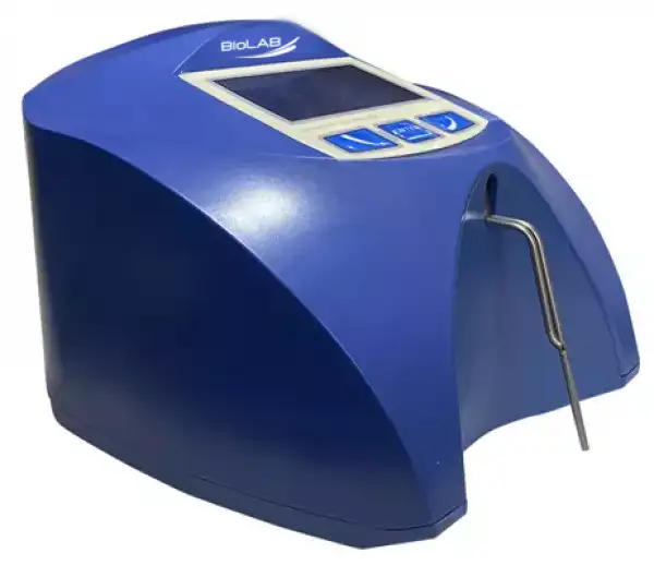
The function of the milk analyzer is to make quick analyses of milk on fat (FAT), non-fat solids (SNF), proteins, lactose and water content percentages, temperature (o С), freezing point, salts, total solids, as well as density of one and the same sample directly after milking, at collecting and during processing.2. TECHNICAL PARAMETERS
2.1. Working modes characteristics:
The program of the milk analyzer has five working modes.2.1.1. Measurement mode milk / dairy product – first type
2.1.2. Measurement mode milk / dairy product – second type
2.1.3. Measurement mode milk / dairy product – third type
2.1.4. Cleaning
2.1.5. Printing
2.2. Measuring range:
Fat ……………… .....................from 0.01% to 25%SNF ………………………………..from 3% to 15%
Density * ……………………… . .from 1015 to 1040 kg/m3
Proteins ………………………… ..from 2% to 7%
Lactose ……………………… ...from 0.01 % to 6 %
Water content …………………from 0 % to 70 %
Temperature of milk ……………from 1oC to 40oC
Freezing point**………………from – 0,4 to – 0,7oC
Salts ……………………………from 0,4 to 1,5%
* Density data are shown in an abbreviated form. For example 27.3 have to be understood as 1027.3 kg/m3 . To determine the milk density, write down the result from the display and add 1000.
Example: result 31,20; density = 1000 + 31,20 = 1031,2 kg/m3
The abbreviated form of the density is used also when entering data for samples in working mode Recalibrate, for example:
If the measured sample density is 1034.5 kg/m3, then in the menu for entering the samples parameters used for calibration, across the parameter Den = , you have to enter 34.5.
** Please, carefully read Appendix Freezing Point.
2.3. Accuracy:
Fat … .. ……………………………… .. … ... ………………… . … ...± 0. 10%SNF ………………………………… .. ………… ... ………… . … ...± 0. 15%
Density ……………………………… ……………………… ..± 0.3 kg/m3
Proteins …………………………… ... …… ... ……………… . … ...± 0. 15%
Lactose ……………………………… . ………………………… ...± 0.20%
Water content ……………………… . . …………………………… .± 3.0%
Temperature of milk ……………… .. . ………………………………± 1oC
Freezing point……………………… .. .. …… ... …………………± 0.001oC
Salts ……………………………… ... … .. ………… ... ………… ...± 0.05%
The difference between two consequent measurements of one and the same milk could not exceed the maximum permissible absolute error.
2.4 Correct ambient conditions:
Maximum permissible absolute error is guaranteed in case of normal ambient conditions:Air temperature……... from 10oC to 40oC
Relative humidity…... from 30% to 80%
Power supply………... 220V (110V)
Extent of contamination at normal environmental conditions……..2

2.5. Dimensions:
………………………… . 175/175/150 mm, mass 1,5 kg2.6. Continuous working time:
…… . …… . ………………………… . … ... …… ....non-stop2.7 Milk sample volume per one measurement:
……………………………… .. ……… .. 15 cm3 (= 25 ml)
Figure 1
Front Panel
1. Upper cover
2. Wide Display
3. Button “Down”
4. Button “Enter”
5. Button “Up”
6. Output pipe
7. Input pipe
8. Sample holder

Figure 2
Back Panel
1. Switching adapter
2. Power switch
3. 12 V printer output
4. pH probe input (option)
5. 12 V input
6. Serial interface (RS232/ printer)

Figure 3
Cable Description
DC 12V Power Supply Milk Analyzer Cable
1. GND
2. No connection
3. No connection
4. 12V DC
3. QUALIFICATION OF RAW MILK, THERMALLY TREATED MILK, OTHER DAIRY PRODUCTS AND DERIVATIVES
3.1. Taking samples and preparation for analyses
In order to receive reliable results in qualification of milk, dairy products and derivatives are needed: precise samples taking; correct samples storing (in need to be preserved); correct preparation before making measurement. The rules and requirements for this are described in details in Appendix Preparing Samples.3.2. Making the measurement.
3.2.1. Preparing the analyzer for working mode3.2.1.1. Put the analyzer on the working place, providing good ventilation and not in the vicinity of heat providing devices or sources. The temperature in the premises has to be in the boundaries 10-30oC.
3.2.1.2. Check if the power switch is in "0" position and that the outlet voltage complies with the voltage indicated on the rating plate of the analyzer. Connect the power supply cable to the electrical outlet.
3.2.1.3. Switch on the “POWER” button, which starts the identification procedure. For a short time the display shows the number of the software versions, for example:

where:
Milkanalyzer xxx is the time for measurement.
MA vers YY is the motherboard software version.
MA ser. N. xxxx is the serial number – written on the rear panel of the analyzer.
These data are called analyzer’s Identity

company-producer, you have to send the data, written on the display during the above described initialization procedure i.e the analyzer’s identity.
3.2.1.4.Till the analyzer is prepared for work (at about 5 minutes) the following message is written on the display: “Getting ready” . Above pointed time is in dependence of the environmental temperature and increases with decreasing the temperature.
3.2.1.5. When the device is ready for work the display shows: “Ready to start” .
The analyzer is ready to make analyses in mode 1 (normally Cow)
3.2.1.6. If you want to pass to another mode press the button Enter and hold it pressed. The following message appears on the display:

Release the button Enter. The display shows the possible working modes:

Using “up”▲and ”down”▼buttons, choose the working mode and press Enter in order to start it.
3.2.2. Making analyses
To start measurement: pour the preliminary prepared sample in the sample holder of the analyzer; put the sample holder in the recess of the analyzer; press the button Enter.
The analyzer sucks the milk, makes the measurement and returns the milk in the sample-holder. During the measurement the temperature of the sample is shown on the display.
Ignore the results received immediately after switching on the analyzer and after measuring distilled water. Make a second measurement with new portion of the same sample.
3.2.3. Displaying the results
3.2.3.1. When the measurement is finished, the sample returns in the sample-holder and the display shows the results. For example:

Where: | |
F= ff.ff | - measured FAT in percentage; |
S= ss.ss | - measured SNF in percentage; |
D= dd.dd | - measured density in percentage; |
P= pp.pp | - measured protein in percentage; |
L= ll.ll | - measured lactose in percentage; |
W= ww.ww | - measured sample’s added water in percentage. |
Table 1

Where,
tt,tC -sample’s temperature;
-0.fff - measured sample’s freezing point;
0.sss - measured salts values;
aa.aa - measured total solids
By pressing the button”Up” ▲ display shows the third page with results:

Where,
L=I.II -measured Lactose in %;
By pressing the buttons “up”▲ and ”down”▼ , the operator has the possibility to pass from one page result to another.
3.2.3.2. Write down the results in the form. The results remain on the display till a new measurement is started. If the analyzer is connected to a computer or a printer, it sends the data to the computer or prints them.
4. CLEANING THE ANALYZER
This procedure prevents gathering milk fat residues and milk stone on the sensor. The milk stone consists of milk solids, calcium, iron, sulphates, magnesium, etc. All these substances form layer on the pipe and sensor’s walls, which leads to deviations in the measurement results and blocking up the piping.

4.1. Periodically cleaning (rinsing) the analyzer
It is done in the process of routine work of the analyzer. Its aim is to prevent drying up and adhesion of different milk components in the milk analyzer’s measuring system.4.1.1. Periodical cleaning frequency.
It is easy to understand what is the period on which the rinsing could be done as the analyzer reminds you when it is necessary. This is done by a sound signal in 1-second cycle after the set time intervals elapse:
• 55 min. after switching on the power supply of the analyser, but idle work;
• 15 min. after the last measurement of real milk sample.
After cleaning completion, new measurement takes place in above described time intervals.
The following message appears on the display:

4.1.2. Making the rinsing
After above message is received put in the recess of the analyzer a glass filled with 120 ml water (in case 1 from p.4. 1. 1.) or alkaline cleaning solution (in case 2 from p.4. 1. 1.).
Press Enter to start the rinsing mode.
In this mode the analyzer makes 3 cycles and stops.
Already used solution is poured out of the analyser. Now the device is ready for the next measurement. In case of doubt that the analyzer is still not well cleaned, the procedure Cleaning may be executed repeatedly.
4.2. Complete cleaning
4.2.1. Complete cleaning frequencyThis cleaning is done after finishing the work with the analyzer at the end of the working day or if it is obvious that the measuring system of the analyzer is contaminated in case of intensive work with it. It is done with alkaline cleaning solution.
Preparation of 3 % alkaline solution of Lactodaily for circulation cleaning in the milk analyzer:
1. Take the package 100 g concentrated chemical Lactodaily
2. In appropriate vessel (for example bucket) pour 1 L water.
3. Add the powder and then again water up to 3 L.

Then follow the instruction for milk analyzer cleaning.
4.2.2. Cleaning
4.2.2.1.Rinsing milk residues
Fill in the glass with water. Put it in the recess of the analyser and start command Cleaning from the main menu. After finishing it pour out the contaminated water.
4.2.2.2.Cleaning with alkaline cleaning solution
Fill in the glass with warm (50-60 C) alkaline cleaning solution. Put it in the recess of the analyser and start the command Cleaning from the main menu. After finishing it, pour out the contaminated liquid.
4.2.2.3.Rinsing with water
Fill in the glass with water. Put it in the recess of the analyser and start command Cleaning from the main menu. After finishing it pour out the contaminated water. Now the device is ready for work.
4.2.2.4. Cleaning with acidic solution
It is recommended to be done every day.
Preparation of 3 % acidic solution of Lactoweekly for circulation cleaning in the milk analyzer:
1. Take the package 100 g concentrated chemical Lactodaily
2. In appropriate vessel (for example bucket) pour 1 l water.
3. Add the chemical and then again water up to 3 l.
The following procedure is executed:
1. Rinsing the milk residues:
Fill in the glass with water. Put it in the recess of the analyser and start command Cleaning from the main menu. After finishing it pour out the contaminated water.
2. Cleaning with acidic solution
Fill in the glass with warm (50-60 C) acidic cleaning solution. Put it in the recess of the analyser and start the command Cleaning from the main menu. After finishing it, pour out the contaminated liquid.
3. Rinsing with water
Fill in the glass with water. Put it in the recess of the analyser and start command Cleaning from the main menu. After finishing it pour out the
contaminated water. Now the device is ready for work.

4.3 Peristaltic pump service

Figure 4
Peristaltic pump
5. POSSIBLE MALFUNCTIONS AND ERROR MESSAGES, TROUBLESHOOTING
In the table below are described the possible malfunctions during the milk analyzer’s exploitation and ways for their repair/remedy. If the problem persists after all recommended measures are taken, please, connect the nearest service center for help. Do not forget to tell the analyser’s identity.
Error message | Possible problem /cause | Repair/remedy |
2 MA overheated Accompanied by a continuous sound signal | Overheated milk analyzer | Immediately switch off the analyzer. Pay attention the analyzer to be situated away from direct sunlight or heating devices. Wait 5- 10 minutes the device to cool down or to be normalized the ambient temperature and switch it on again |
3 Empty Camera | Insufficient quantity of the milk sample sucked in the system or air in the sample | The analyzer is ready to measure the next sample. In order to avoid the future appearance of the same error message, please, check the following: - The sample is prepared according the instructions and there aren’t air bubbles in it. - There is a real suction of the sample after starting measurement, i.e. it is obvious that the level of the milk sample in the sample holder decreases. In other case – there is damage in the suction system. - Avoid the end of the suction pipe to be above the surface of the liquid (not dipped enough). - Avoid curdling of the milk sample. Clean immediately if there is a sample curdled in the system. - In mode Measurement, after starting the measurement, remove the sample holder and see if there is no milk poured |
back in the sample holder. | ||
4 Sample Overheat | Sucked overheated sample | The analyzer is ready to measure the next sample. In order to avoid the future appearance of the same error message, please, check the following: -The sample is prepared according the instructions and its temperature does not exceed the maximum permissible sample’s temperature. -Complete the procedure for checking the analyzer in case of error message Empty Camera. |
Table 2
6. MAKING CORRECTIONS AND CALIBRATION OF THE DEVICE
In the process of work with the analyser there is a possibility the results to start differing between the data for some of the measuring parameters when measured with the milk analyzer and the corresponding reference method of analyses (Gerber for fat, Kjeldhal for proteins etc). In order to establish the possible discrepancy and to correct the readings of the milk analyser do the following:6.1. Taking samples and preparation of samples for checking the accurracy of the milk analyser, making corrections and recalibration
This is a basic moment for the correct checking the accuracy of the analyser and for making correct and precise correction and calibration. It is accomplished according Appendix Sampling and preparation of samples for verification the accuracy of the milk analyzer, making corrections and recalibration.6.2. Determination the type of the discrepancy:
6.2.1. Making measurementsMake measurements with different samples (not less than 3) with known values of a separate parameter (for example fat content), determined by the known reference methods of analyses (for example Gerber's method for determination of fat content). For more accuracy it is recommended among these samples to be also such with values, close to the lowest and highest bounds for the measured parameters.
Make 5-time measurement for each of the samples. Calculate the average value for each sample parameter, without taking into consideration the first measurement for each sample.
6.2.2. Analysing the measurement results
Make comparison between the values of the parameter from the reference sample and measured with the analyser. Make analyses of the difference received.
6.2.2.1. If the received differences are relatively constant value for samples with different content of the analysed parameter, it is necessary to make correction.
For example
М% of the reference samples: 2,20 3,00 3,80 4,60 5,20
М%average when measuring
with the analyser: 2,38 3,17 4,01 4,79 5,42
Difference: 0,18 0,17 0,21 0,19 0,22
Conclusion: the difference is relatively constant value and correction is possible to be done with – 0,2 % (see Corrections, p6.3.3) 6.2.2.2. If the differences are not a constant value it is necessary recalibration to be done. For example. М% of the reference samples: 2,20 3,00 3,80 4,60 5,20 М% when measured with the
analyser: 2,02 2,93 3,76 4,75 5,44
Difference: -0,18 -0,07 -0,04 0,15 0,24
Conclusion: It is obvious that the difference is variable value and recalibration have to be done (See Recalibration, p.6.4).
6.3. Making corrections
.3.1. Possible corrections, limits and changing stepsEvery parameter from each calibration may be separately corrected. Below is the table with possible corrections, limits and changing steps:
Parameter | Increasing | Decreasing | Step |
FAT | 0.95% | 0.95% | 0.01% |
SNF | 4.75% | 4.75% | 0.05% |
Density | 4.75% | 4.75% | 0.05% |
Lactose | 0.95% | 0.95% | 0.01% |
Salts | 0.95% | 0.95% | 0.01% |
Proteins | 0.95% | 0.95% | 0.01% |
Added water | 9.00% | 9.00% | 1.00% |
Sample’s temperature | 9.90o С | 9.90o С | 0.1o С |
Table 3
6.3.2. Preparing the analyzer for mode Corrections
6.3.2.1. Press the button Enter and without releasing it switch on the power supply of the device, wait for the starting identification messages and release the button after the following message appears on the display:

After releasing the button on the display is shown:

followed by possible to be entered by the operator menus:

6.3.2.2. By using buttons “ up” ▲ and “down” ▼position on Corrections and press Enter.
6.3.3. Making correction
6.3.3.1 Determining the correction mode
When starting Corrections, the following appears on the display

By using buttons “up”▲ and ”down”▼position on the corresponding calibration (for example Correction 1 – cow) and press Enter.
6.3.3.2. Choosing correction parameter
After choosing calibration mode the display shows the following:

Using the buttons “up”▲ and ”down”▼position on the action you want to take (for example Edit) and press the button Enter.
6.3.3.3. Making correction
After choosing parameter (for example fat) the display shows the following:

Using the buttons “up”▲ and ”down”▼is possible to increase or decrease the value of the measured parameter in the above pointed limits. Leaving this mode means saving the correction value and activating it.
6.3.3.4. Making verification
After the corrections are made put the milk analyser in working mode and make several times measurement of reference samples with known values of the corrected parameter. If the difference between the values of the parameter from the reference methods and milkanalyser are in the limits for the parameter it may be considered that the correction is successfully made. If the discrepancy between the measurements from the milk analyser and classical methods is bigger than is necessary to make second correction according above described way.
If after the second correction the results are unsatisfactory we recommend making a calibration of the analyser. In dependence of the conditions and your requirements you may make the calibration using a personal computer type IBM PC and the company's calibration program or autonomous - by recalibration.

6.4. Recalibrating the milk analyser
6.4.1. Running the analyser in mode Recalibrate6.4.1.1. Press the button Enter and without releasing it switch on the power supply of the device, wait for the starting identification messages and release the button after the following message appears on the display:

After releasing the button on the display is shown:

Followed by the possible to be entered by the operator menus:

6.4.1.2. By using buttons “up” ▲ and “down” ▼ position on Settings and press button Enter.
6.4.1.3. Analogically, position on Recalibrate and press the button Enter.
6.4.2. Making recalibration
6.4.2.1. Determining the calibration mode
After starting Recalibrate, the display shows the following:

6.4.2.2. Entering values for the separate sample parameters
Wait for the sound signal and the following menu on the display:

In this display is possible to be entered the results from the milk with high FAT chemical analyses, which were received by the methods from Appendix
Methods.
For example:
- by using the buttons “up” ▲ and ”down” ▼ , choose the needed parameter to be entered;
- by pressing “Enter” the cursor will mark the number to be changed. For example: FAT=01.29;
- using the buttons “up” ▲and ”down” ▼ , enter the needed value;
- by next pressing of Enter pass towards the next number;
- after completion of entering the needed FAT value, press Enter;
- the cursor returns to its starting position.

With the button “down” ▼ move the cursor across SNF and analogical to the above described consequence enter the value for SNF and after that the rest of the values.
Using menus Edit samp's 1(2,3) the operator has the possibility preliminary to prepare the data for the parameters for each recalibration separately or to check the sample data.
6.4.2.3. Making recalibration with the available samples
After entering the values for the separate parameters of the sample position the cursor across Exit, press Enter and the following menu appears on the display:

which reminds us to put 5 times the sample with high FAT.

Stir 2-3 times the milk sample before each measurement by pouring it from one vessel to another. The needed quantity is poured in the sample-holder and it is put in the recess of the device. Starts the measurement. The sample is sucked. Appears the following menu:

After the sample is measured, appears the following menu:

which reminds to make the next measurement. Follow the procedure till the 5th measurement.
After 5th measurement completion automatically appears the menu:

Which reminds to enter the values for the sample with low FAT. Enter the values analogically to the procedure, described in the previous sample. After entering the last parameter position the cursor on “Exit”, press “Enter” and the following menu will appear:

Make 5 times measurement of the low FAT sample.
After 5th measurement completion automatically appears the menu:

Which reminds for 5-times water measurement. There is no need to enter values after placing the sample-holder. Measurement starts directly.
After the 5th measurement appears the menu:

This means that the calibration was completed successfully and the analyzer is recalibrated for cow milk, marked as “Cal: Cow” .
Switch off the power supply of the device and switch it on again. The device is ready to work with the new calibration.
If during work the sample’s temperature exceeds the temperature range 15- 25° С the following message appears:

Wait till the end of the measurement. When the message appears:

Put sample with temperature in the temperature range and continue the
measurement till completion of 5-time measurement.
7. STARTING THE DEVICE IN A SERVICE TEST/SETUP
OPERATIONAL MODE. MENUS DESIGNATION
7.1. Starting the device in a service Test/Setup operational mode.
In order to start the Setup of the device the operator has to press the button Enter and without releasing it to switch on the power supply of the device, to wait for the starting identification messages and to release the button after the following message appears on the display:

After releasing the button on the display is shown:

Followed by possible to be entered by the operator menus:

You may move in the menus by using buttons “ up” ▲ and “down” ▼ .
If by pressing the button Enter you choose a menu, each menu offers new points/submenus. When Exit is chosen the device leaves the Setup mode and returns to normal work.

7.2. Menus Function:
Serve for choosing special (technological) working modes. After starting it the following appears on the display:
This mode is normally used in production conditions.
7.2.1.2. Calibration mode
In mode Calibration the analyzer is ready to make measurement and to send the received results towards the technological milk analyzers calibration system. For this purpose you need personal computer type IBM PC, company’s calibration system LSC.EXE and methods for calibration of milk analyzers (see the corresponding documents). To start measurement in this mode, the operator has to put a sample-holder containing milk sample in the recess of the analyzer and to press the button Enter.
7.2.1.2. Cycle mode
Mode Cycle serves for training the analyzers. When you start this mode, the analyzer, without additional commands, sucks the sample, makes the measurement, pours the sample out in the sample-holder and displays the received results cyclically.
Note:
This mode is normally used in production conditions. It is recommended the customer to calibrate the device using the embedded function Recalibrate (i.e autonomous, without computer)
7.2.2. Corrections
Serves for entering corrections in the measured data. Detailed description in point 6.3.2 and 6.3.3.
7.2.3. Settings.
Serve for assigning different working parameters (modes).
7.2.3.1. Net number.
Serves for assigning the device network number when connecting it in the production network. The possible numbers are from 0 to 15 including.
After starting this function the display shows the following:

By using the button “up”▲ the operator has the possibility to increase the number, showing the channel’s number, and by button “down”▼ , to decrease it. Pressing the button Enter saves the chosen channel and exits the function.

7.2.3.2. Recalibrate.
Serves for changing definite calibration. Methods are described in point 6.4.
7.2.3.3. Save/Rest Cal.
Through this menu you may save the new calibration in the device or to restore the old one (factory) calibration. This is necessary in case that you’ve calibrated the device for cow milk, but after that the device is not measuring correctly and you decide to restore the factory calibration settings. Position the cursor across “Restore calibration” and press “Enter”
Possibilities:
Save calibration – saves the chosen calibration in an internal buffer. Restore calibration – restores the chosen calibration from the internal buffer. The procedure Save/Restore is done for each calibration separately.

Current calibration content is not changed, the analyzer continues using it, but there is a reserve copy in an internal buffer.

The current calibration is replaced with the calibration from the internal buffer and the analyzer starts working with it. The content of the internal buffer is not changed.

7.2.3.4. Settings Page 2.
After this menu is started the display shows the following:

Now there is a possibility one of the following options to be set:
7.2.3.4.1. Set Calibr Name.
Sets the names of the separate calibrations. The name could be chosen from the group of predefined calibrations names or to edit a new one. When editing the new name there is a possibility all ASCII codes to be used, as letters (caps and normal), numbers and punctuation marks and popular symbols. The calibration name consists of 8 symbols.
Example:
When it is suitable to us this possibility of the analyser? For example if you have a device factory calibrated for Cow milk, Sheep Milk and UHT milk, but yоu need oftenly to measure camel milk. Using the methods, explained in details in Appendix Methods you may make a new calibration without need to send the analyser back to the producer for calibration. Using this procedure you may make calibrations for most oftenly analysed milk and to write down the exact
calibration name, which will be shown on the display and printed on the printer. After starting this menu the display shows:

There are the following possibilities:
With button OK – to start editing the name of the chosen calibration.
With button Prev – to choose the previous calibration, chosen for setting the calibration name.
With button Next – to choose the next calibration name for editing.
If the operator has chosen and confirmed calibration for change of the name, the display shows (example):

There are the following possibilities:
With button PreDef – to choose a calibration name from the list of preliminary given names.
With button Exit – to leave the menu.
With button Edit – to edit the new calibration name.
If a name from the preliminary given names list is chosen, the display shows:

There are the following possibilities:
With button Exit – to leave the menu.
With button Yes – to confirm the chosen from the list calibration name.Now the program returns to the beginning of the menu for setting calibration names. With button Next – to show the next calibration name from the list. If it is decided a new calibration name to be edited, the display shows:

There are the following possibilities:
With button Prev – to display the previous ASCII symbol.
With button Set – to confirm the ASCII symbol, shown on the display and passes to editing the next symbol from the calibration name.
With button Next – to show the next ASCII symbol.
The editing finishes by entering the eighth symbol from the name of the calibration.
7.2.3.4.2. Select High Fat
If the analyzer has embedded function for measurement of high fat products, by this menu the calibration, with which this measurement to be made is chosen. What is seen when this option is turned on is obvious slow down of the sample’s suction speed.
7.2.3.4.3. HFSpeed for Cal
If the analyzer has embedded function for measurement of high fat products, and a new calibration for high fat measurement is needed, before starting the new calibration the operator has to start this menu. What is seen when this option is turned on is obvious slow down of the sample’s suction speed during calibration. Please, pay attention to the fact that switching off the power supply cancels this command action.
7.2.3.4.4. Reslt Precision
Serves for setting the precision of the measured results shown on the display. It is set separately for every parameter, the precision could be 0.01 (standard) or
0.1.
7.2.3.4.5. PCB Main Identi
Gives information about the type and the version of the analyser (LS Identity).
7.2.3.5. Set Base Frpoint.
Serves for editing the Basic Freezing Point. It is used by the customer according the Appendix for calculation of the added water and determination of the Freezing point of the sample.
7.2.4. Tests.
Start different tests. Possibilities:
7.2.4.1. Test pump.
Starts pump’s test. The number of the completed suction/display cycles is indicated.
7.2.4.2. Ultrasound.
Test for the ultrasonic system. Used in production conditions.
7.2.4.3. Set Amplitude.
Serves for ultrasound amplitude adjustment. It is used under production conditions or by the customer (after sensor change) according the instructions in the document SetCell.pdf.

7.2.5 Exit
By pressing the button you may leave the program and pass towards another menu.
7.2.6 Milk analysers’ setup menu structure
Analyzer Setup
Special
modes
Calibration
Cycle
Corrections
Measurement
Temperature
Settings
Net number
Recalibrate
Save Calibr
Restore Calibr
Settings Page2
Set Calibr Name
Select High Fat
HFSpeed for Cal
Reslt Precision
PCB Main Identi
Set Base FrPnt
Tests
Test pump
Ultrasound
Set Amplitude
8. Additional possibilities of the analyser
8.1. Connecting to 12 V DC power supply.If there is a need the analyzer to work on place without electrical supply available, then it could be powered by car battery or other 12 V DC external power supply. Use the 12 V power supply cable, supplied with the analyser.
8.2. Connecting to IBM PC
The milk analyser can be connected to IBM PC using the RS232 interface cable. In order to make the connection: switch off both milk analyser and PC.Connect the RS 232 cable towards Serial interface and towards the computer. Turn on both milk analyser and PC. Now the milk analyser is ready to communicate with IBM PC. This is enough for starting the program for collection and archive of the measurement results.
8.3. Connecting a printer (option).
In order to print out the measurement results, a serial printer could be connected to the device – for example ESC/POS Serial printer, production of Datecs or Seiko. The interface connector for the printer is on the rear panel of the device – “Serial printer output” . The printer (if it is Datecs), should be connected to the “12 V printer output” on the device rear panel. Connect it via cables, delivered by the company-producer. If the printer is connected directly to the electrical network, then the analyzer and the printer should be connected to one and the same electrical phase. Communication parameters: 9600 bps, No parity, 8 bits, 1 stop bit. It’s one-way communication (uses one line) – the analyzer only sends and the printer only accepts data.
APPENDICES
APPENDIX 1: EASY CALIBRATION OF THE MILK ANALYSER BY CALCULATING THE BASIC PARAMETERS VIA FORMULAS

1. Determination some of the parameters by formulas
There is dependence between the different parameters in milk and its density, which may be expressed with mathematical equation. On this base different formula, tested and confirmed by the classical laboratory methods for analyses, are developed. We recommend the following:
2. SNF determination.
For determination of SNF the correlation dependence exists between the milk’s density, fat and SNF in the milk. When the density and the fat are known, the SNF can be calculated.
There are several formulas with different applicability.
А/ When the salts and fat are known
SNF is calculated by subtracting the fat percentage from the salts. SNF = Salts – F (%)
Where
Salts – salts in (%),
F– fat content in (%),
This formula is used for determination of SNF in whey, buttermilk, and cream.
B/ Known quantity of fat and density (most commonly used method when maximum accuracy is needed).
We recommend the following formula:

This is a universal formula and actual for milk of almost all kind of cows and sheep all over the world.
3. Determination of lactose content
We recommend the following formulas:
А/ for cow milk
Lact. = SNF * 0,55 (% )
Where
SNF– content of SNF in percentages (%),
0,55– constant coefficient.
B/ for sheep milk
Lact. = SNF* 0,45 (% )
Where,
SNF–solids-non-fat content in percentages (%),
0,45– constant coefficient.

4. Determination of salts content
We recommend using the following formulas:
А/ for cow milk
Salts = SNF* 0,083 (% )
Where
SNF– solids-non-fat content in percentages (%),
0,083– constant coefficient.
B/ for sheep milk
Salts = SNF * 0,075 (% )
Where
SNF– solids-non-fat content n percentages (%),
0,075– constant coefficient.

5. Determination of total proteins content
We recommend using the following formulas:
А/ for cow milk
Protein = SNF * 0,367 (% )
Where
SNF- solids-non-fat content in percentages (%),
0,367– constant coefficient.
B/ for sheep milk
Protein = SNF * 0,475 (% )
Where
SNF– solids-non-fat content in percentages (%),
0,475- constant coefficient.

APPENDIX 2 FREEZING POINT DETERMINATION
1. Methods for determination.
The milk analyzer determines the freezing point of each sample and the quantity of added water. The milk analyser does not measure the freezing point, but calculates it from the components it depends on. The basic components in the milk are water, solids, lactose, FAT, proteins, minerals (salts) and acids. The freezing point depends only on the diluted in the milk components and quantity of the solvent (in the milk it is water). The ultrasonic technology allows direct measurement of FAT, proteins, lactose + salts (the soluble components, only influencing the freezing point), and the quantity of the solvent in % is determined by 100 % – total solids %, total solids = lactose % + FAT % + proteins % + salts % + acids %.
Without understanding the meaning of the freezing point – determined or shown from the milk analyzer added water result easily may lead to a mistake for the value of this parameter.
2. The basic freezing point.
Milk freezes at lower temperature than water. The average freezing point of the raw milk in the most regions is at about -0,540°С . The average reading for your region is called “basic” freezing point.
The freezing point of milk is a “physiological constant” . This does not mean that it will not vary. In fact feed, breed, season, time of lactation, climate, whether the sample is taken at the beginning, middle or end of lactation – all these factors will have an effect on the freezing point of the individual sample. This means that there is an average value of all these numbers. The more samples used in obtaining this average, the more reliable it is as a base. Or the basic freezing point is an average of freezing points of milk, taken from many cows. When a laboratory checks a producer, it is only comparing the average of the producer’s cows against a larger area average.
The Health authorities establish the basic freezing point or agriculture departments in some regions, sometimes by universities, separate dairy producers, or their associations. Frequently, tolerances have been established on top of a basic freezing point to allow some variations in the milk as well as device or operator variations.
Without mentioning the basic freezing point, the Association of Official Analytical Chemists now recommends an upper limit freezing point at - 0,525°C (2,326 standard deviations above the most recently determined North American average of –0,5404°C), below which there will be at 95%
confidence that will show 99% of all freezing point determinations on unwatered milk:
“if the freezing point is –0,525°C or below, milk may be presumed to be free of water or may be confirmed as water free by tests, specified below. If the freezing point is above –0,525°C, milk will be designated as “presumptive added water” and will be confirmed as added water or added water free by tests specified below. Evaluate extreme daily fluctuations in the freezing point of herd, pooled herd, or processed milk for presence of added water” . “Presumed added water”, as described above, must be “confirmed” by means of tests on authentic milk samples obtained as specified in the АОАС
METHODS.
After determination the freezing point of your sample via the milk analyzer, the added water is calculated using the following formula:

Where:
FrPointBase is the basic freezing point
FrPointCalc is measured freezing point
Note:
If the freezing point is not correctly determined, the result for the added water is not valid. In this case results for FrPoint and AddWater are not shown on the display and on the printout from the printer. If the density of the measured sample is 0, the result for AddWater is not valid and is also not shown on the display and the printouts.
Sample:
First variant
If you’ve entered for milk analyzer basic freezing point -0.520°C (according article 5.9 of the EU Milk Hygiene Directive 92/46/ЕЕС), measured freezing point –0.540°C, using the above pointed formula you’ll receive –3,8%. Because it is not possible the added water to be negative value, the milk analyzer indicates 0% added water. The reason for this is the tolerance in the basic freezing point, reasons for which are described below.
If in the same milk we add 3,8% water, and the basic freezing point is the same, the milk analyzer will measure freezing point –0.520°C, and will indicate again 0% added water.
Second variant
If you’ve entered for the device basic freezing point –0.540°C, measured freezing point –0.540°C, the milk analyzer will indicate 0%. When you add 3,8% water, the device will indicate 3,8%-added water.
From the above mentioned follows that it is very important to enter correct basic freezing point in the device.
The device’s results for added water may give information about doubt of added water in the milk and the exact value of this added water may be determined after a “cowshed sample” is taken and the result for the freezing point, measured by the milk analyzer of the “cowshed sample” is entered as basic freezing point in the formula for calculation of added water.
Then the result from this formula will give us the absolute value of the added water for the corresponding milk supplier.