Extreme Environment Shaker BSOT-204
- Sea, Air, Door to Door Shipping
- 1 Year Warranty
- US & European Standards
Our product is an accurately designed, microprocessor controlled with double Decker platform to save your valuable lab space. Three eccentric shaft balancing drive ensures shaking with uniform speed. Speed adjustment settings permit both gentle and vigorous shaking. Varieties of platforms are available for different glassware and vessels.
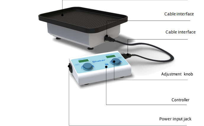
- Shaker is controlled by a ribbon cable.
- The controller can be fixed on the incubator or placed on the workbench.
- Large platform design, many samples can be placed, strong load-bearing capacity.
Specification
Features
Optional Accessories
| Speed Range | 50~300 rpm |
| Timing Range | 1 min~99 h 59 min |
| Digital Display | Time/speed display |
| Radius of gyration | 10 mm |
| Max Load Capacity | 2.5 Kgs |
| Motor Parameters | Brushless DC motor |
| Platform Dimension | 330 mmx430 mm |
| Beep Alarm | Yes |
| Voltage | 100~240V AC 0.75A 50/60 Hz |
| Power | 30 W |
| Fuse | 250 V,1 A,φ5x20 |
| Controller size | W.220xD.132xH.64 mm |
| Shaker size | W.270xD.320xH.112 mm |
| Net Weight | 8 kgs |
- Shaker is controlled by a ribbon cable.
- The controller can be fixed on the incubator or placed on the workbench.
- Large platform design, many samples can be placed, strong load-bearing capacity.
| Accessory Code | Name | Description |
| 2001409006 | Platform A | flat platform with rubber mat |
| 2001409007 | Platform B | platform with clamps for flasks 250-300 ml*12 |
| 2001409008 | Platform C | platform with clamps for flasks 100-150 ml*20 |
| 2001409009 | Platform D | universal platform with springs |
Operating Manual for BSOT-204
Chapter 1 Introduction
Chapter 2 Specifications
1. The Normal Operation Condition
2. The Basic Parameters and Specifications
Chapter 3 Preparation
1. Structure Description
2. Keyboard and Display Panel
3. Key Function
4. Power Connection
5. Platform Installation
Chapter 4 Operation Guide
1. Speed and Timing Setting
2. Stop / Start
3. Alarm
Chapter 5 Failure Analysis and Troubleshooting
Appendix A:Wiring Diagram of Extreme Environment Shaker
Chapter 1 Introduction
BSOT-204 shaker is suitable for use in CO2 incubators, greenhouses, and refrigerators. The parameter display and controller are placed outside. There is no need to worry about humidity, high temperature and other factors affecting the performance and life of the instrument. It is very suitable for animal cell culture and suspension cell culture and high and low temperature chemical reactions. The controller can be attached to most incubators by magnets to optimize the operating space.Features:
- The controller can be placed outside the incubator, and the shaker is controlled by a ribbon cable, which is convenient for viewing and changing settings without disturbing the environment of the incubator.
- The controller can be fixed on the incubator or placed on the workbench.
- Suction cup machine feet, super shockproof, high speed and stable, no noise.
- Large platform design, many samples can be placed, strong load-bearing capacity.
Chapter 2 Specifications
1. The Normal Operation Condition
Can be used in CO2 environment, incubator or cold room Operating environment temperature (shaker): -10 ~ 60°C Operating environment temperature (controller): -10 ~ 50°CRelative Humidity: 100%
Power: AC110V/220V 50/60Hz ,50/60HZ
2. The Basic Parameters and Specifications
| Model | BSOT-204 |
| Speed Range | 50~300 rpm |
| Time Range | 1min~99h59min |
| Digital Display | Time/speed display |
| Radius of gyration | 10mm |
| Max Load Capacity | 2.5Kgs |
| Motor Parameters | Brushless DC motor |
| Platform Size | 330mm×430mm |
| Beep Alarm | Yes |
| Voltage | 100~240V AC 0.75A 50/60Hz |
| Power | 30W |
| Fuse | 250V,1A,φ5×20 |
| Controller size | W.220×D.132×H.57mm |
| Shaker size | W.270×D.320×H.88.5mm |
| Net Weight | 8kgs |
Chapter 3 Preparation
This chapter mainly describes the instrument’s mechanical structure, the keyboard and functions of each key, as well as preparations before power on. Please learn this chapter well before the Extreme Environment Shaker is to be operated at the first time.1. Structure Description
2. Keyboard and Display Panel
3. Key Function
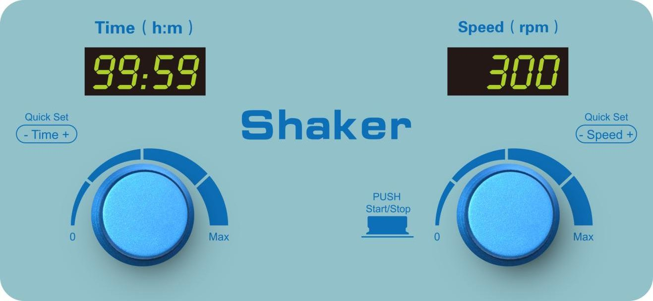
 Left side: Rotate the knob to the right, the time increases. Rotating to the left is the opposite. Right side: Rotate the knob to the right to increase the speed. Rotation to the left reduces the speed.
Press the knob and the instrument starts to run, and press the knob again to stop the instrument.
4. Power Connection
Put the instrument on a horizontal and even working table, insert the cylindrical socket of the power cord into the power input socket on the back of the instrument as shown in the figure, and connect the other end of the power cord to the grid. The grid voltage is required to be within the range of AC100~240V.
5. Platform Installation
The Extreme Environment Shaker can be equipped with four type of platforms: Platform A, Platform B, Platform C, Platform D. Platform Platform A (Stainless steel platform and rubber pad combination)
 Erlenmeyer flask platform Platform B (250ml can hold 12)
 Erlenmeyer flask platform Platform C (100ml can hold 20)
 Universal platform Platform D
Platform installation steps:
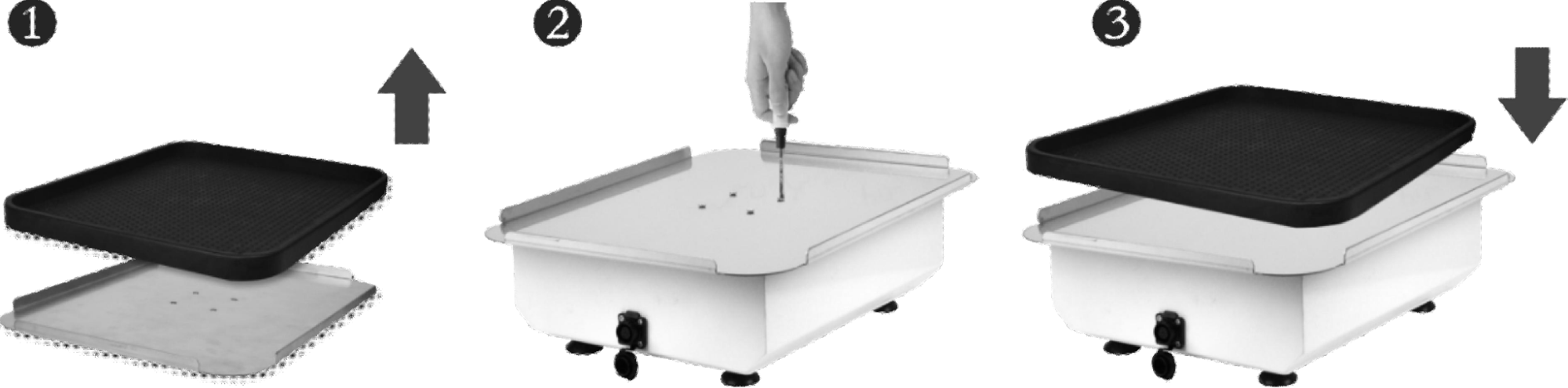
1. Remove the rubber pads on the
2. Fix the platform on the host with four screws.
3. Then put the non-slip back on the platform.
Chapter 4 Operation Guide
1. Speed and Timing Setting
 - Turn on the power switch, the instrument enters initialization, the display screen is as shown on the right, accompanied by a beep sound.
  - Speed setting: Image 130, PictureTurn the right knob to set the speed value immediately. After you stop turning the knob, the instrument automatically confirms the implementation of the new set value and saves the set value. As shown on the right. To increase the modification range, turn the knob quickly. As shown on the right, it is 300.
 - Time setting: Image 131, PictureTurn the left knob to set the time immediately. After you stop turning the knob, the instrument automatically confirms the execution of the new set value and saves the set value. As shown on the right. To increase the modification range, turn the knob quickly. As shown in the figure on the right, it is 8:56. When the operation ends, there will be a buzzer prompt. NOTICE : When the time is set to 00:00, it means the running timing is ∞.
2. Stop / Start
- Short press the right knob to run the current program. When the timing ends, the operation stops, and the buzzer sounds an alarm.- After running, the instrument displays OVER, press any key or turn the knob to enter the standby interface.
- During operation, short press the knob on the right side to stop the operation. Press this key again to restart the operation.
3. Alarm
- During operation, the communication line is disconnected, Err is displayed, and the buzzer alarms.- When the operation is over, OVER is displayed. When the motor speed drops, the communication line is disconnected, Err is displayed, and the buzzer alarms.
- Press any key to restore the display.
Chapter 5 Failure Analysis and Troubleshooting
Failure Analysis and Processing Procedures| No. | Phenomenon | Possible Causes | Processing Procedure |
| 1 | No signal display when power on. | No power | Check the power |
| Broken switch | Exchange the switch | ||
| Others | Contact with the seller | ||
| 2 | Shaking heavily | Samples placed imbalanced | Place the samples evenly |
| 3 | Actual speed and displayed speed are not matching | Broken controller | Contact with the seller |
| 4 | Err displays | Speed out of control | Contact with the seller |
| 5 | Knob does not work | Broken button | Contact with the seller |
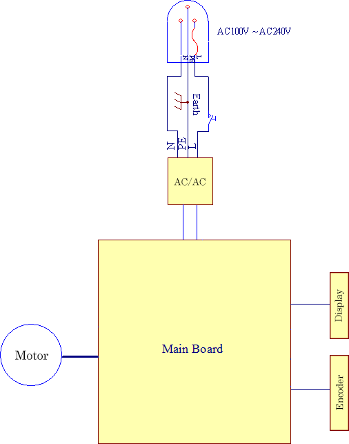
Appendix A:Wiring Diagram of Extreme Environment Shaker
(Below diagram is just for reference. It is subject to change without prior notice.)