


Drying Oven BODR-7102
- Sea, Air, Door to Door Shipping
- 1 Year Warranty
- US & European Standards
- 304 stainless steel, mirror polishing processing, semicircular arcs at corners easy to clean and maintain. The space between the shelves in the chamber is adjustable
- PID controller with over temperature alarm and timing function ensures precise and reliable control
- Ceramic fiber door seal, which can run at high temperature for a long time and has a long service life
- Programmable controller: 7 periods 63 steps, 0 ~5999mins for each period, can preset boot and shutdown time, adjustable circulating fan
Specification
Features
| Capacity | 100 L |
| Electrical requirement | AC 380 V 50 HZ |
| Temperature Range | RT+20°C 400°C |
| Display Resolution | 0.1°C |
| Temperature Stability | ±0.5°C |
| Ambient Temperature | +5 - 40°C |
| Power Consumption | 4050 W |
| Internal Dimension | 450Wx450Dx450H mm |
| External Dimension | 990Wx790Dx990H mm |
| Shelves | 2 pcs |
| Timing Range | 0~5999 min |
- 304 stainless steel, mirror polishing processing, semicircular arcs at corners easy to clean and maintain. The space between the shelves in the chamber is adjustable
- PID controller with over temperature alarm and timing function ensures precise and reliable control
- Ceramic fiber door seal, which can run at high temperature for a long time and has a long service life
- Programmable controller: 7 periods 63 steps, 0 ~5999mins for each period, can preset boot and shutdown time, adjustable circulating fan
- Independent over-temperature alarm system ensures experiments running safely
Operating Manual for BODR-7102
1. Safety Prompting
2. Brief Introduction
3. Operational Instructions
1. Preparation
2. Power on
3. Operation steps
4. Ways to improve the accuracy of temperature control
5. Function parameter table
6. Usage of“ Over-temperature Protector” (optional)
4. Maintenance and Notes
5. Appendix
1. Technical Specifications
2. Troubleshooting
Packing List
 Prompting for Safety Assurance
Matters prescribed herein are critically important, which must be practically observed.
1. Safety Prompting
! Danger (likely to cause serious property losses or human casualties)1. The Product must be reliably grounded (without taking the zero line or neutral line as the earth wire).
2. Before using, make sure to confirm the compliance of power supply voltage and frequency with the product requirement.
3. Use a separate power supply socket for the product and confirm the plug and socket are properly grounded.
4. It is not allowed to pull out or plug in the power supply plug at random without switching off the power when the product is in operation.
5. It is not allowed to extend or cut short the power supply connection wire of the product at random.
6. It is prohibited to place in any inflammable, explosive, evaporative and erosive substance for drying or curing.
7. It is prohibited to touch the door, OBW and ambient surface with the product operating at a temperature above 80°C to avoid any scald.
8. Do not put hands or other articles into the air inlet/outlet (slot).
9. It is prohibited to repair without permission and in case of being consigned by the Company for any repair, maintenance shall be carried out by the professionals.
! Warning (Unauthorized repairing may cause damage or injury )
1. Make sure to read and understand adequately the operating instructions of the Product before operating.
2. Since 304 stainless steel inner chamber is not acid-resisting, make sure to take corrosion-proof measures and never use any acid media in the case!
3. Make sure not to directly drag the power cable when pulling out the power supply plug.
4. In case of any one of the following circumstances, make sure to pull out the power supply plug of the Product:
4.1 When replacing the fuse tube.
4.2 When checking and repairing the product with fault.
4.3 When keeping the product idle for long.
4.4 When moving the product.
5. Do initiate the upper deviation alarm function after power on.
! Attention (likely to affect the useful life and cause the abnormal operation of the product)
1. The product shall be placed on a hard and firm plane so that it will remain in a level status.
2. Certain gap shall be kept around the product.
3. The product must be used under the specified conditions.
4. Make sure not to open/close the product door by force, otherwise, it may easily cause the door to drop off, damage the product and result in an injury accident.
2. Brief Introduction
1. Structure and FunctionsThis system simulates natural environment of high temperature and is widely used in high temperature adaptability testing (especially on changes to electric performance and mechanical performance) of electronic, electric products and components.
Product Design:
1). Auto adjustment of temperature can ensure precise temperature control.
2). Artificial-intelligence controller.
3). The system contains over temperature, overload and short circuit protection mechanism, which can automatically shut down affected equipment and initiates alert. Safety is guaranteed.
4). The inner tank is made of stainless steel, which is aesthetic and is easy to clean.
5). The housing of the system is made of electrostatic sprayed steel with smooth finishing for aesthetic feeling.
Note: This system is tested and used in high-temperature environment. The inner tank, shelf board and door seals carry color changes. This does not affect the functions of the system.
3. Operational Instructions
1. Preparation
Operation Environment:1.1 Ambient Temperature: 5℃~40℃.
1.2 Relative humidity is not higher than 85%.
1.3 Atmospheric Pressure: (86~106)KPa.
1.4 Altitude is not higher than 2000m.
1.5 No strong vibration source and strong electro-magnetic fields around..
1.6 The product should be placed horizontally and stably in indoor environment without severe dust pollution, direct sunlight and corrosive gas.
1.7 Keep sufficient clearance around the system as indicated in the above figure. Do not place the system under a fire alarm.
1.8 See technical specifications for power voltage (Table 3 of Schedule 1).
1.9 Rationally place and adjust the shelf boards. Ensure sufficient upper/lower and surrounding clearance to promote smooth air circulation! (>100mm), Weights on the board should not bend the board.
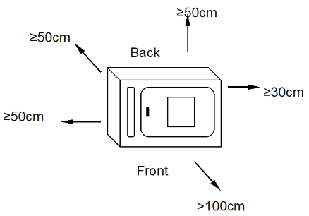
Figure 1
2. Power on
2.1 Close the door of the box, the handle should be vertically downward.2.2 Turn on the power and the indicator light is on.
2.3 The controller enters the working mode after about 4 seconds of self-checking procedure.
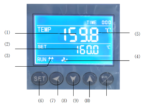
Figure 2
2.4 Indicator light description.
1) TEMP area (PV): display the measured temperature.
2) SET area (SV): display the set temperature.
3) Heating lamp: the lamp is on when there is heating output.
4) Fan indicator light: on when there is fan output.
5) TIME: Time display window; display running time or parameter value.
2.5 Button description
6) SET button: used to modify the set value or enter the internal parameter setting, in the parameter setting state, long press the set button for more than 3 seconds to exit.
7) Shift key: used to shift the set value, internal parameters and view the ambient temperature.
8) Decrease key: used to modify the set value, various parameters, or start/stop auto-tuning.
9) Increase key: used to modify the set value, internal parameters, or view the remaining period (X)
10) RUN/STOP: Press for 3 seconds to run or stop the controller.
2.6 Check temperature control accuracy
2.6.1 Select a digital thermometer with a resolution of 0.1℃ that has passed the verification and is within the verification period as a standard and put it into the product work room, and ensure that the sensor temperature sensor is in the geometric center of the work room.
2.6.2 Choose a point within the temperature control range of the product and set the SV temperature control value. When the PV measurement value is equal to the set value, keep it at a constant temperature (1~2) hours or so (depending on the product specifications, the constant temperature time may vary) , Observe that the difference between the actual measured temperature value of the standard thermometer and the measured value displayed by the controller PV should be ≤±0.5℃.
3. Operation steps
1) Temperature setting: Press the "SET" button once, the value of the SET window flashes, indicating that the temperature can be set as required, and the required temperature can be set through the "increase", "decrease" and "shift" keys. Press the "SET" key again to return to the standard display mode.2) Timing function: Press the "SET" button twice, when the time is set to 0, there is no timing function; when the time is set to 0, the controller has a timing function, press the "SET" button, the TIME value flashes, indicating the time can be set as required. Use the "increase", "decrease" and "shift" keys to set the required time value. When the time is up, the TIME window displays the "END" buzzer, and you can press any key to silence it.
Note: ① Each time you modify a parameter, you need to press the "SET" key to confirm and the modification is effective.
② After setting all the parameters, press the "RUN/STOP" key and wait for about 3 seconds to start running.
4. Ways to improve the accuracy of temperature control
4.1 After the product has been used for a period of time, the temperature control accuracy should be checked according to the method 2.6, if it exceeds ±1℃, it can be corrected according to the following method:4.1.1 Enter the parameter setting, find the
 symbol.
After the formula is calculated, it shall be modified on the basis of the original PK value at the time of delivery (Note: One correction is not accurate, and the correction can be repeated until it meets).
5. Function parameter table
In the standard state, press the SET key and the shift key at the same time for more than 3 seconds, the LCD screen displays the LK code, and you can enter the password setting level interface.1)When LK is displayed in the output area of the LCD screen, press the plus or minus key or the shift key to make LK=0000, and press the SET key to enter the user parameter level setting.
| Symbol | Name | Setting range | Description | Factory set value |
| Pn | Work group in operation | 0~8 | For program control only. To set up the work group for operation of meters. When Pn is set as 8, Group 8 is for fixed value control. | Optional |
| Cy | Number of cycle in a period | 0~99 | Special parameter for program control. When CY is 0, the meter will run between the work group all the time. When CY is not 0, the meter will shut down automatically after CY in the group. | Optional |
| dy | Appointment boot selection | 0-99::59 | 0: No appointment; for other values, after pressing the run key to start, it will automatically delay the dy time and then start the machine. | |
| ut | UV time | 0-200 minute | Turn off the UV lamp after ut time, ut=0, turn off the UV lamp manually. | Optional |
| uS | UV switch | 0-1 | 0: Turn off the UV light 1: Turn on the UV light. | Optional |
Table1
2)When LK is displayed in the output area of the LCD screen, set LK=0003, and press the SET key to enter the equipment manufacturer's parameter level setting.The parameter hierarchy menu of the equipment manufacturer is as follows:
| Symbol | Name | Setting range | Description | Factory set value |
| tM | Setup of maxi temperature permissible by the instrument | full range | Stop heating beyond maxi temperature and give alarm. | |
| Po | Boot mode | 0~2 | ①When PO =0, after open the power, the controller in a stopped state, by long press star/stop key is up and running. ②When PO =1, after open the power, the controller will be running. ③When PO =2, running from last power began to run. | |
| AL | Setup of alarm | 0~100.0 | When the temperature exceeds the value of SP+AL, the alarm light is on and the alarm is output (with HOLD function). | |
| Pb | Zero adjustment (intercept) | -100.0~100.0 | When the zero error of the instrument is greater and the full scale error is smaller, the value should be adjusted. As a rule with Pt100 the value is seldom adjusted. | |
| PK | Adjustment of full scale (slope) | -1000~1000 S | When the zero error of the instrument is smaller and the full scale error is greater, the value should be adjusted. PK=4000 × (specified value-actual display value)/actual display value and as a rule with Pt100 the value is adjusted first. | |
| PA | Onboard room temperature sensor correction | -30-30 | When there is an error between the on-board room temperature sensor and the actual situation, adjust the value. | |
| 2b | The second zero correction | -100-100 | When the second channel zero error is large and the full scale error is small, adjust this value. Generally, Pt100 rarely adjusts this value. | |
| 2K | Second channel full scale adjustment | -1000~1000 | When the zero error of the second channel is small and the full-scale error is large, adjust the value. PK=4000× (mercury thermometer value-display value)/display value, generally Pt100 adjust this value first. |
Table 2
※The products have been strictly tested before leaving the factory. When the technical indicators meet the requirements and work normally, no correction is generally required.
6. Usage of“ Over-temperature Protector” (optional)
The over temperature protector is a separate protection system. When the temperature controller encounters malfunction and causes temperature out of control and when the temperature in the working room reaches the set value, the overheat protector will cut off the heating and initiate the alarm.(See Fig. below)working room temperature is lower than set temperature limit The protection system is released after set value and the meter is restored. Cycle repeats until problem is solved.
5.1 Set value is higher or equal to (SV+AL)+ (10~15)℃
5.2 See Fig. 6, Use + and — button for over temperature setting on control panel.
To set desired temperature limit.
Example: SV=130℃, AL=10
Set the over temperature to 150℃.
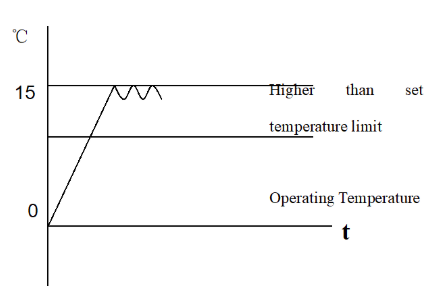
Figure 3
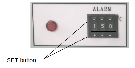
Figure 4
4. Maintenance and Notes
1. Turn off the power after each use. After testing in the environment with temperature higher than 300℃, first turn off the power and then turn off the electric motor after twenty minutes. Disconnect the three-pin plug after high temperature testing. Be aware of the heat and avoid being burnt when opening the door and taking out articles from the cabinet.2. Clean the inside and outside of the system, disconnect the plug and cover the system with plastic dust guard if the system will not be used for a long period.
3. Clean the testing cabinet with a vacuum cleaner or blow the system with compressed air once a month.
4. Power on the system to drive away moisture regularly (around once a month) if the system is placed in a high-humidity environment.
5. Check and calibrate the control precision before reuse or in case of requirements change.
6. Modification to parameters other than TEMP, TIME, would require consent of out Customer Service Center or should be implemented by authorized personnel.
5. Appendix
1. Technical Specifications
This product is manufactured pursuant to Q/TIWY 1—2007| Model Indicator Item | BODR-7101 BODR-401 | BODR-7102 BODR-402 | BODR-7103 BODR-403 | BODR-7104 BODR-404 |
| Supply Voltage | AC 380V 50/60Hz | |||
| Temperature Control Range | AH:RT+20~400℃/ BH:RT+20~500℃ | |||
| Temperature Resolution/Constant Temperature Fluctuation | ±0.5℃ | |||
| Input Power (W) | 3250 4050 | 4050 4900 | 4900W 6050W | 8500W 8500W |
| Inner Tank Dimensions W×D×H(mm) | 350*350*400 | 450*450*450 | 600*600*600 | 980*1000*780 |
| Product Dimensions W×D×H(mm) | 890*700*920 | 990*790*990 | 1140*950*1140 | 1324*1263*1770 |
| Shelf board | 2 pcs | |||
Table 3
Note: 1. RT: room temperature 2. The above data is based on measurement with a mercury thermometer with 0.1℃ resolution in ± the environment of 25℃ and 85% relative humidity 0.1℃ (the head is placed in the center of the environment).
2. Troubleshooting
| Problem | Cause | Action |
| No power (Power indicator is not on.) | Power outage of socket or poor contact with the plug | Repair |
| Power cord is broken or poorly plugged | Repair, replug | |
| power switch is broken (or no turned on) | Replace the switch or turn on the switch | |
| Fuse is broken | Check the switch, electric motor, heater, temperature controller and other parts for short circuit or 0 insulation resistance, and start the system after repairing. | |
| The screen displays “□□□□” | Sensor is damaged or connection wires breaks (or fall off) | Repair or replace Pt100 |
| Temperature does not grow | Timing function is initiated? And set time is up | See “timing function” |
| Temperature controller is broken (no output) | HEAT indicator does not light up or 3061 broken, replace | |
| TRIAC has no connectivity | Replace the TRIAC (model: BTA16 or BTA26) | |
| Phase loss of three-phase power, or contactor failure | Check the three-phase power and switch; turn of the switch again, replace the contactor | |
| Heating tube wires disconnect or short circuit | Repair or replace | |
| Inaccurate temperature control (big static error) or The temperature keeps growing and becomes uncontrollable (The buzzer sounds) | HEAT indicator does not light up, and the temperature keeps growing | SCR is broken, replace it |
| The fans are not turned on or damaged (does not rotate) | Turn on or replace the fans | |
| Gap between room temperature and set temperature is too small | Minimum temperature controllable is RT + 10℃ | |
| Poor Pt100 contact, causing bigger resistance. | Reconnect the wires | |
| Incorrect settings of Ar and P parameters | Reset parameters | |
| Incorrect Pb and Pk | Reset Pb and Pk | |
| A group of heaters or heating plates are damaged (Only applicable to model 9420 or 9620) | Replace | |
| Abnormal noise or louder noise | Fan bearings is broken or lack of lubricating oil | Refill lubricating oil, replace fan |
| Rubbing back air channel boards | Repair (add washer) |
Table 4
Packing List
Product Name: High-temperature Dry Oven| No. | Type | Item | Unit | Quantity | Remarks |
| 1 | Document | User Manual | 1 | ||
| 2 | Document | Packing List | share | 1 | |
| 3 | Accessories | Shelf board | pcs | 2 |
Packaging list conforms to articles in the package
Packed by: 2 Tested by: 1