


Benchtop Shaking Incubator BSBT-1705
- Sea, Air, Door to Door Shipping
- 1 Year Warranty
- US & European Standards
- Unique air flow technology adopts continuous flow fan technology, air stability, no turbulence, temperature is uniform
- Cycle fan speed can be automatically controlled, it can avoid the samples volatile too fast due to cycle fan is too fast
- Patented single-axis drive and balancing technology, running stable,low noise and low consumption
- Adopts pneumatic support, transparent cover height can be adjustable to any position, convenient the operation
Specification
Features
| Speed Range | 40-500 rpm |
| Temp. Range | RT+5 - 65°C |
| Temp. Control accuracy | 0.1°C |
| Frequency accuracy | ±1 rpm |
| Platform Dimension | 250x250 mm |
| Inside height | 195 mm |
| Overall Dimension | 390Wx590Dx370H mm |
| N.W | 32 Kg |
| Amplitude | 4 mm |
| Running time | 1 - 99h59min |
| Power requirement | AC 220 V / 50 Hz |
| Rated power | 450 W |
| Standard configuration | 250mlx8pcs |
- Unique air flow technology adopts continuous flow fan technology, air stability, no turbulence, temperature is uniform
- Cycle fan speed can be automatically controlled, it can avoid the samples volatile too fast due to cycle fan is too fast
- Patented single-axis drive and balancing technology, running stable,low noise and low consumption
- Adopts pneumatic support, transparent cover height can be adjustable to any position, convenient the operation
- Colorful touch screen can continuously, accurately and real-time display temp, rotation speed and work time
- The menu operation interface is easy to understand
- Combine incubator, shaker functions together with small space
- Patented overall design, transparent big view windows, dynamic master the culture effect
- Shaking platform and chamber are made of stainless steel, anti-corrosion and easy to clean
- Protection on instruments: Comply international standard secondary temp. limiter alarm system, alert the operator with sound and light alarms, ensure operator is safe without any accident
- Protection on key components: Key components have over current, over temp., over load etc safety protection, it can prevent instruments accidents without precautions
- Brushless DC motor, large start torque, wide speed adjustment, free maintenance
Operating Manual for BSBT-1705
1. Working principle
2. Performance description
3. Scope of application
4. Definition of terms
5. Instruction for Safety
5.1 Danger !
5.2 Warning!
5.3 Caution!
6. Structure and composition
6.1 Host structure
6.2 Display and commands
6.3 Operation steps
7. Cleaning and maintenance
7.1 Product moisture treatment:
7.2 Points to note
8. Notes
8.1 Use environment requirements
8.2 Specifications
8.3. LCD screen function parameter table
9. Troubleshooting
Packing List
1. Working principle
The constant temperature shaking incubator is an advanced constant temperature culture equipment that combines the functions of the oscillator and the incubator. It mainly realizes two parameters of temperature and speed control, achieving scientific and reasonable oscillation culture purposes. Creatively utilizing the principle of single-axis drive technology to provide a light and reliable speed, the medium is always oscillating. The heating wire is used to heat the rear part of the box, and the airflow in the box is continuously circulated through the cross-flow fan to maintain a constant temperature in the entire box. The heating power of the electric heating tube is controlled by the PID controller, and the high-precision temperature sensor is used to ensure accurate and stable temperature inside the box.2. Performance description
Humanized design● It integrates the incubator and the oscillator into one, and it occupies a small area.
● Patented design, transparent large window design, wide viewing angle, dynamic mastering of training results.
● With reserved test holes, the external temperature can be measured in real time by an external sensor (optional).
● The inner body of the box is made of stainless steel, which has strong anti-corrosion ability and is easy to clean.
● Low heat dissipation DC brushless motor, large starting torque, wide speed regulation, maintenance-free, break through the defects that the existing domestic shaker could not run continuously for a long time.
Security function
Technical characteristics
● Protection of equipment: The second set of temperature limit alarm system conforms to international standards. When the heating is out of control or exceeds the maximum limit temperature, the heating is automatically cut off, and the sound and light alarm is used to remind the operator; the equipment is safely operated without accidents;
● Protection of key components: Critical electrical components are equipped with over-current, over-temperature, overload and other safety protection to prevent accidental equipment;
● Protection of samples:
1. When the door is opened, the breeze circulation, heating, and oscillation speed are automatically stopped, and there is no disadvantage of temperature overshoot;
2. When the temperature inside the box is higher or lower than the set temperature, the alarm starts to cut off the heater, and the sound and light reminds the operator;
It can protect the sample from normal test without accidents;
● Provide fault information: When the device fails, the display will display a fault message to ensure that the fault information is clear at a glance.
3. Scope of application
The temperature control range of the constant temperature shaking incubator is RT+5~65°C. The speed range is shown in Table 1. It integrates the functions of the incubator and the oscillator, provides precise temperature control, realizes shock culture, and meets the suspension culture of bacteria and microorganisms. The demand is an ideal instrument for cell culture, fermentation, biochemical water quality analysis, plant cultivation, breeding and other experiments.4. Definition of terms
1) Temperature range: refers to the precise and stable temperature range that can be provided and used in the box;2) Temperature fluctuation: refers to the range in which the central temperature point in the tank fluctuates at different times, and “±” indicates the range of upward and downward fluctuations;
3) Speed: The speed of rotation per minute, expressed in rpm, ie rpm.
5. Instruction for Safety
5.1 Danger !
The improper use of this unit may cause property damage and / or personnel injury.1. This product must be earthed reliably and kept far away from electromagnetic interference source (Zero line or neutral line should never be used as earth wire).
2. Please ensure the voltage and frequency of the power supply is compatible with the incubator power requirements prior to use.
3. The product should be connected to a separate power outlet and both the plug and outlet are earthed properly.
4. It is not allowed to pull off or insert the power plug wantonly without turning off the power switch while the product is in operation.
5. It is not permissible to lengthen or shorten the power line at random.
6. No repairs may be done without permission and the equipment must be maintained by an electrician entrusted by our company.
5.2 Warning!
Caution (It may cause serious loss in property or injuries and deaths)1. Operation shall be done only after the directions for use are read and understood fully.
2. SUS 304 container is not acid-resistant, anti-corrosive measures should be adopted and acidic medium should never be used in the incubator.
3. The power line should never be drawn directly when pulling off the plug.
4. In one of the following cases, the power plug must be pulled off:
• Replacement of fuse.
• Under inspection and repair when the product fails.
• Suspension from use for a long time.
• In movement.
5. When the equipment works on the bench, a crowning barrier should be built at the edge to avoid shifting of the oscillating box due to long-time work and falling from the bench, to cause serious loss in product or property injury and deaths.
5.3 Caution!
Otherwise its service life may be affected, resulting in its inability to work regularly.①The product shall be mounted on a solid and firm plane, keeping it horizontal.
②Some space shall be left around the product.
③The product must be put into use under given working conditions.
④Never open/close the box door with a force, otherwise the door will fall away and the product injured causing casualties.
⑤In case of suspension from use for long, the product should be dehumidified regularly to avoid damage to relevant devices.
6. Structure and composition
6.1 Host structure
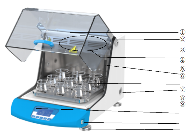
Figure 1
1. Glass cover
2. Glass cover hinge
3. Air duct hole
4. Pneumatic support rod
5. Replaceable fixture (see configuration table)
6. Independent temperature limit controller
7. Controller
8. Power switch
9. Adjustable foot
6.2 Display and commands
6.2.1 Display introduction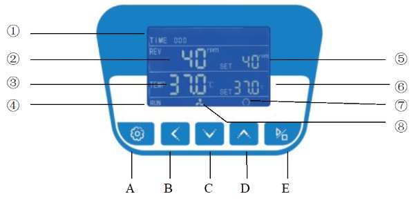
Figure 2
1. TIME: Time display window, when controller is running, TIME window will display the running time.
2. REV: Showing measured rotate speed.
3. TEMP: Showing measured temperature.
4. Heating lamp: It lights up when the heating output.
5. REV SET: Showing set speed or the parameter code.
6. TEMP SET: Showing set temperature or the parameter value.
7. Circulating fan pilot lamp: It lights up when there are fan outputs.
8. Oscillating indicator: It lights up when oscillating output.
6.2.2 COMMANDS and DESCRIPTION
1. A
 Mode key: It is used for changing the set value, calling out parameters or confirming the change in parameters.
2.
 shift key: In setting mode, click this key could move the digits.
3.
 Decrease key: Under the set mode, click this key and one number will be decreased pressing this key without stop the number will be decreased continuously.
4.
 Add key: Under the set mode, click this key and one number will be added, pressing this key without stop the number will be increased continuously.
5.
 Start/stop key: Pressing this key for over 4 seconds will control start /stop of the program.
6.3 Operation steps
6.3.1 Temperature setting1) The temperature setting range is RT+5℃~65℃ (BSBT-105 setting range:4℃~65℃);
2) The factory default setting is 25 °C. (Note that the temperature setting is adjusted to 25 ° C when the equipment is stopped);
3) Temperature setting
Clicking and pressing
 the key, the “TEMP SET” value will flash, indicating temperature can be set as required. Using the
  key or
  key, you can set required temperature. If you press once more, you can return to standard mode.
6.3.2 Speed setting
1) Speed setting range is see <Sheet 1>;
2) Factory speed setting default value is 0rpm;
3) Speed setting
When the device is turned on, press the button
, switch to the speed setting display box, the temperature value starts to flash, then press the button or , the speed setting value will increase or decrease, select the required speed, press the speed setting to complete.6.3.3 Time setting
1) The time setting range is 0-99H59min;
2) The factory default setting is 0, that is, the running time is not limited.
3) Time setting
Press the button
, the time dialog box will start flashing, then the time setting can be made, then press the button or , the time value will increase or decrease, select the time to be set (in minutes), Then press the time setting to complete.Note: The set time is the running time, expressed in minutes. When press the button
 the timing starts. After the time is over, the heating and rotation will stop automatically, or press under working condition, the heating and rotation will stop.
6.3.4 Start and stop control
is start and stop button, when the temperature and time setting is over, press 4~5 seconds when everything is ready, the shaker starts to work, When the working time is set to 0, it will automatically stop working, If you need to stop working before the time reaches 0,press and hold for 4~5 seconds to stop working.6.3.5 Alarm function
1) When the oscillating load is too heavy and the motor is overloaded for more than 10 seconds, the meter beeps and the oscillation stops. Press any key to silence.
2) When the temperature in the box reaches the set temperature, the timing starts to run, the timer will stop automatically when the timer ends, and a beep will sound, press any button to silence the sound;
3) When Pt100 generates a fault such as disconnection or short circuit, so that the measured temperature is greater than 60 °C or less than -1.0 °C, the LCD displays “------”;
4) The setting of the upper deviation alarm is reasonable, which can protect the system from over-temperature or out-of-control. It must be used when the product works. For example, if the product is set to AL=3.0, the alarm temperature is: (set the temperature value) +AL value) °C
6.3.6 Use of optional "independent temperature limit controller"
The over temperature protector is an independent protection system. When the temperature of the temperature controller is out of control, when the temperature in the working chamber reaches the temperature limit setting of the over temperature dial, the over temperature protector will automatically cut off the heating and sound an alarm.
(as shown below figure 3) When the working room temperature is lower than the temperature limit °C.After the set value, the protection system is eliminated and the instrument resumes work.
Loop this way until troubleshooting.
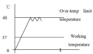
Figure 3
The specific operation is as follows:
6.3.6.1 The temperature limit setting should be greater than or equal to(SV+AL)+ (3~5)℃
6.3.6.2 See Figure 4, using the over-temperature setting dial on the panel+, — button to set the required temperature limit temperature.
Example: SV=37°C, AL=3 Should be set at 40 ° C
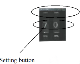
Figure 4
7. Cleaning and maintenance
7.1 Product moisture treatment:
1) After each use, dry the surface of the cabinet with a dry cloth to prevent rust.2) When the product is not used for a long time (more than one month), it should be energized regularly. The machine runs at 50r/min for 5 hours to prevent moisture and rust. After the end, the power cord should be unplugged.
3) If the product is placed for a period of time or intermittently for more than half a year, the tray should be pushed by hand to see if it can be rotated and then used for power-on;
4) In addition to parameters such as speed and time, other relevant parameters should be modified by our company's service center or adjusted by professionals;
5) When the equipment is placed on the platform, the table edge must be provided with a raised barrier to prevent the oscillation box from being displaced after long-term operation and a drop phenomenon.
6) Defrost treatment (products with "C" in the end)
1) When the product is running below the ambient temperature for a long time or when the cooling effect is deteriorated (the static difference is generated), the product should be defrosted.
2) Set the temperature of 40 °C, let the product work (3~5) hours, then resume the working temperature, and the speed is put into working state.
7.2 Points to note
1) After the product is placed for a period of time or intermittently for more than half a year, or the process parameters (temperature) are changed, the temperature control accuracy check should be performed.2) In addition to parameters such as temperature, speed, time, zero point full point correction, etc., other relevant parameter modifications should be approved by our company's service center or adjusted by professionals.
3) For low-temperature products with “C” in the tailings, when the equipment is being transported, the inclination should not exceed 45 degrees to avoid damage to the refrigeration system.
4) After the product with the “C” in the endnote is placed in place, it should be turned on again after 1~2 days to facilitate the normal operation of the compressor in the refrigeration system and prolong its life.
5) When the equipment is placed on the table, the table edge must be provided with a raised barrier to prevent the oscillation box from being displaced after long-term operation and a drop phenomenon.
6) After the equipment is grounded, if the ground is not flat, it must be leveled and cannot be used for tilting; the left and right sides of the equipment should be kept more than 50cm. Especially for products with "C" in the end (with refrigeration system). If the equipment is used at an ambient temperature above 30 °C, it is recommended to strengthen the ventilation measures behind the equipment and reduce the ambient temperature to prevent the compressor from crashing due to overheating.
7) This equipment should be kept away from electromagnetic interference sources and should have a good grounding wire.
8. Notes
8.1 Use environment requirements
1) Indoor use.2) Ambient temperature: 15 ° C ~ 35 ° C,
Relative humidity is not more than 85%.
3) Power supply: 220V 60HZ.
4) Atmospheric pressure: (86 ~ 106) KPa.
5) The altitude is not higher than 2000 meters.
6) There is no strong vibration source and strong electromagnetic field around.
7) It should be placed on a stable, horizontal and sturdy surface (floor) without direct sunlight. The working environment is free of serious dust and no corrosive.
8) As shown in the above figure, there should be a space gap of no less than 10 cm around the product (front, back, left, and right); a space gap of not less than 50cm should be left.
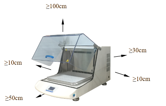
Figure 5
8.2 Specifications
| MODEL Specification | BSBT-1705 | BSBT-1706 | BSBT-1707 | BSBT-1708 | |
| Temperature Range | Amb +5℃~65℃ | 4℃~65℃ | |||
| Temperature Resolution | 0.1℃ | ||||
| Shaking Speed Range | 40~500rpm | ||||
| Speed adjustment accuracy | ±1 | ||||
| Amplitude | 4mm | 5mm | 5mm | 5mm | |
| Timing Range | 0~5999min | ||||
| Internal height(mm) | 195 | 265 | 330 | ||
| Platform Size(mm) | 250*250 | 350*350 | 450*450 | ||
| Exterior Dimension (mm) | 390*370*590 | 490*450*590 | 590*550*825 | 590*550*975 | |
| Electrical Requirement | AC220V 60Hz | ||||
| Power Consumption | 450W | 650W | 1000W | 1300W | |
| Note: If you need to customize the fixture, the number of physical specifications is subject to customer requirements. | |||||
Table 1
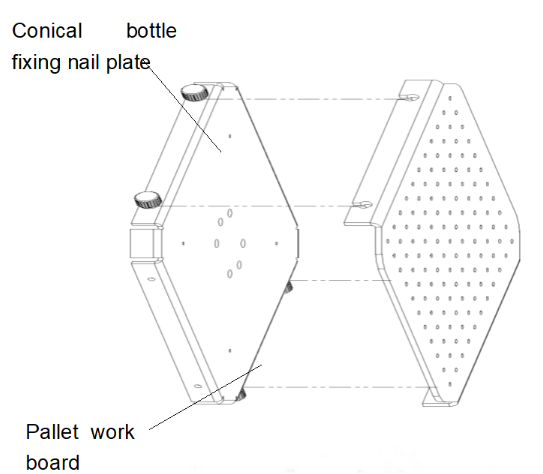
Optional fixture classification:

Conical flask clamp fixing plate(Standard)
(Need to be equipped with flask clamp or test tube rack)
Features:
The conical flask clamp fixing plate is used for mounting and fixing the conical flask, test tube rack or other jig.
Note: The factory configuration conical flask clamp is configured in 250mL.
The number that can be placed
| Flask clamp capacity | BSBT-1705 | BSBT-1706 | BSBT-1707 | BSBT-1708 |
| 50ml | 16 | 36 | 49 | 49 |
| 100ml | 9 | 23 | 36 | 36 |
| 250ml | 8 | 13 | 18 | 18 |
| 500ml | 4 | 8 | 16 | 16 |
| 1000ml | — | 4 | 9 | 9 |
| 2000ml | — | 1 | 4 | 4 |
Table 2
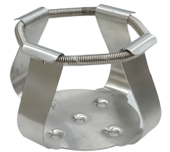
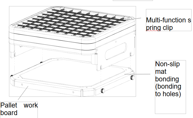
 Universal spring clip (Optional) | Features: Multi-function spring clip, a variety of test tubes, Erlenmeyer flasks and other shaped vessels can be placed. | ||
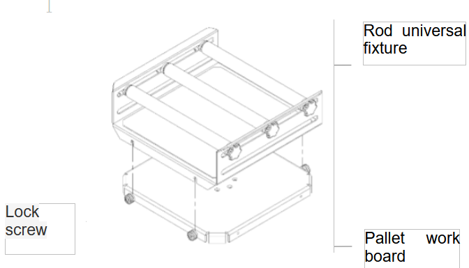
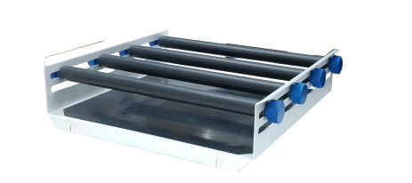 Rod universal fixture (Optional) | Features: The rod universal fixture is suitable for all types of containers, and the variable pinch roller allows for universal adjustment of the container. Suitable for all sizes of flat bottom flasks. (including accessories: basic bracket, clamping roller, fastening screw, anti-slip mat), | ||
 Flat plate universal fixture (Optional) | Features: Flat plate universal fixture is used in the viscosity range of low-smooth shaking operations, such as cell culture, culture dishes, culture media in culture flasks and culture dishes, and containers with low center of gravity. (Includes accessories: non-slip mat) | ||
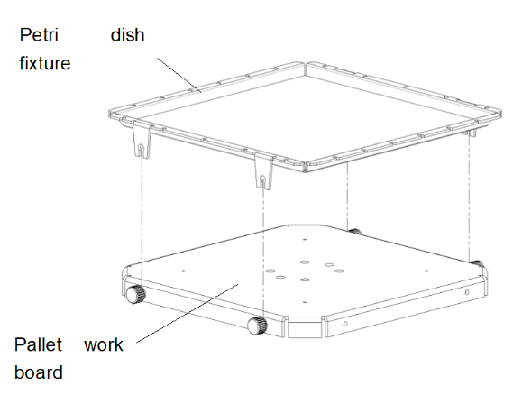
 Petri dish tray (Optional) | Features: The Petri dish tray is composed of an aluminum plate and a black elastic rope, and can fix the culture bottle or the shaped bottle body. | ||
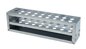 Test tube rack (Optional) | Features: Made of stainless steel for easy placement and removal of test tubes. The test tube rack is designed to strongly shake and fix small tubes, test tubes, cuvettes, centrifuge tubes, and the like. | ||
 Beaker clip (Optional) | Features: Different tubes can be sorted and mixed on the same platform, and different sizes of glassware can be mixed. The specifications of the flask holder can be selected. The beaker clip is made of stainless steel and can hold the conical flask and the cylindrical bottle. | ||
Table 3
Fixture installation diagram:
Type 1
1. Rotate the locking screw on the working plate of the tray counterclockwise to loosen it, leaving a certain distance.
2. Align the four card slots on the spring clip with the distance left when the locking screw is loosened in the first step, press down to lock the four card slots, and tighten the locking screw clockwise.
Note: Remove the protective film from the non-slip mat before use.
Type 2
1. Rotate the locking screw on the tray working plate counterclockwise to release it, leaving a certain distance;
2. Align the four card slots of the rod-type universal fixture with the distance left in the first step when the locking screw is loosened. Press down to clamp the four card slots, and lock the screws clockwise. Tighten it. Note: Other types of fixture installation methods are similar.
Note: Install in a constant temperature culture shaker, please use a cross recessed countersunk head screw to fix the hole.
Type 3
1. Rotate the locking screw on the tray working plate counterclockwise to release it, leaving a certain distance;
2. Align the four slots of the Petri dish holder with the distance left in the first step when the locking screw is loosened. Press down to clamp the four slots and tighten the locking screw clockwise. Yes;
3. Please tear off the protective film on the non-slip mat before use.
Note: Other types of fixture installation methods are similar.
Type 4
1. Rotate the locking screw on the tray working plate counterclockwise to release it, leaving a certain distance;
2. Align the four slots of the conical bottle holder with the distance left in the first step when the locking screw is loosened. Press down to clamp the four card slots. Lock the screws clockwise. Tighten it;
Note: Other types of fixture installation methods are similar.
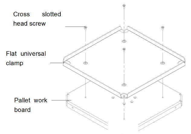
Type 5
1. Align the flat universal clamp with the four holes of the tray working plate;
2. Secure with a Cross slotted head screw and tighten with a Cross screwdriver.
3. Please tear off the protective film on the non-slip mat before use.
8.3. LCD screen function parameter table
When LK is displayed in the output area of the LCD screen, set LK=0003, and press the SET key to enter the equipment manufacturer's parameter level setting.The parameter hierarchy menu of the equipment manufacturer is as follows:
| Symbol | Name | Setting range | Description | Factory set value |
| tM | Setup of maxi temperature permissible by the instrument | full range | Stop heating beyond maxi temperature and give alarm. | |
| Po | Boot mode | 0~2 | ①when PO =0, after open the power, the controller in a stopped state, by long press star/stop key is up and running. ②when PO =1, after open the power, the controller will be running. ③when PO =2, running from last power began to run. | |
| AL | Setup of alarm | 0~100.0 | When the temperature exceeds the value of SP+AL, the alarm light is on and the alarm is output (with HOLD function). | |
| Pb | Zero adjustment (intercept) | -100.0~100.0 | When the zero error of the instrument is greater and the full scale error is smaller, the value should be adjusted. As a rule with Pt100 the value is seldom adjusted. | |
| PK | Adjustment of full scale (slope) | -1000~1000 S | When the zero error of the instrument is smaller and the full scale error is greater, the value should be adjusted. PK=4000 × (specified value-actual display value)/actual display value and as a rule with Pt100 the value is adjusted first. | |
| PA | Onboard room temperature sensor correction | -30-30 | When there is an error between the on-board room temperature sensor and the actual situation, adjust the value. |
Table 4
9. Troubleshooting
| Item | Problem | Problem reason | Solution |
| 1 | No power supply when start | Power outlet no power or poor contact. | Inspection, repair. |
| The power line is broken. | Replace. | ||
| Power switch is not open or break down. | Open (closed) switch or replace it | ||
| Fuse is blown or Fuse is not installed. | Install the appropriate fuse, check the cause of the fuse burning, after boot repair. | ||
| 2 | The machine doesn’t work when turns on | Control power is not open; Running key is not pressed. | Operate according the user manual. |
| Controller or the motor and other components bad is broken | Replace. | ||
| 3 | The screen shows “-----” | Sensor Pt100 is broken | Repair, check when Pt100=0℃ is 100Ω, Each increase of 1 ℃ increase of about 0.3Ω. |
| 4 | The temperature doesn’t rise up; The temperature stop rising after a period of time. | Setting temperature is below the ambient temperature. | Reset |
| Check the timing setting. | Reset enough time or setting the time as 0. | ||
| The controller has no voltage output. | Controller is broken, replace or repair. | ||
| Both side of heating pipe has voltage | Heating pipes fall off or breakdown | ||
| Door switch failure | Adjust the position of the hasp or replace the broken switch | ||
| 5 | The actual temperature shows error/ | Accuracy goes wrong | Zero and full degree correction and require professional debugging is required |
| 6 | It has Static error or large overshoot | The parameter is set unreasonable. | Set temperature value <(RT+5)℃or need professional debugging and modifying P、I、D data. |
| 7 | Temperature is out of control. | The heater is broken | Replace. |
| The controller is broken | Replace. | ||
| Fan does not run; the actual temperature is low in working chamber. | Repair, replace. | ||
| 8 | Big Noise (Including the cooling fan) | The product placement is not stable, The screw of fasten Fan pallet fan is loosen. | Repair. |
| 9 | Oscillation does not work or out of control | The optical chopper is broken or cable poor contact | Replace the optical chopper and repair |
| Dashboard is broken | Replace dashboard | ||
| Motor does not turn. | Motor overload or breaks down, the door switch is not touching well. Need repairing or replacing. | ||
| Door switch is broken. | Adjust the position of the hasp or replace the broken switch. | ||
| 10 | Rotation is not up | The mechanical transmission section has stuck phenomenon. | Hand Test. |
| Small starting torque | Modify the relevant parameters need professional debugging |
Table 5
Packing List
| No. | Type | Name | Unit | Qty. | Remarks |
| 1 | Equipment | Shaking incubator | 1 | Determine the model according to the order number | |
| 2 | Document | Operating instructions | 1 | ||
| 3 | Document | Packing list | 1 | ||
| 4 | Spare part | Power cable | 1 | ||
| 5 | Spare part | Fuse | 2 |