


Automatic Nitrogen Generator BGEN-602
- Sea, Air, Door to Door Shipping
- 1 Year Warranty
- US & European Standards
Designed in such a way that not only removes the hassle of having to change over cylinders, it provides an uninterrupted supply of gas at a consistent purity. Features like low operating cost, environment friendly, safe, enegry efficient makes it an ideal choice for laboratory.
- Automatic control, constant pressure, constant flow
- Ultra high molecular membrane separation technique, PCAN carrier and precious metal catalyst
- Deoxidation and Dehydration device, high purity
- Compact, frees up valuable space
Specification
Features
Applications
| Nitrogen purity | Oxygen content<3PPM |
| Flow Rate | 0-300 ml / min |
| Output Pressure | 0-0.4 Mpa |
| Humidity | <85% |
| Environmental Temperature: | |
| 1-40°C | |
| Pressure Stability | <0.003 Mpa |
| Dimension | 370x180x330 mm |
| Consumption Power | 60 W |
| Power Supply | 220V±10% 50Hz |
- Automatic control, constant pressure, constant flow
- Ultra high molecular membrane separation technique, PCAN carrier and precious metal catalyst
- Deoxidation and Dehydration device, high purity
- Compact, frees up valuable space
- Easy operation, meliminate the need for expensive gas cylinder
- Safe and reliable
Analytical chemistry, Spectroscopy, Pharmaceutical, General laboratory, Food Packaging, Reducing fire hazards, Manufacturing of stainless steel, Wine bottling, LC-MS Gas Chromatography, Fire protection, Glass Industry.
Operating Manual for BGEN-602
1. INTRODUCTION
2. DESCRIPTIONS FOR EACH PART OF INSTRUMENT
3. INSTALLATION AND OPERATION
3.1 Preparation before the operation
3.2 Self checking of instrument (Never connect with gas chromatograph)
3.3 Operation of instrument (Connect with the gas chromatograph)
4. WORKING PRINCIPLE AND FEATURES OF INSTRUMENT
4.1 Working principle:
4.2 Features of instrument
5. TROUBLING SHOOTING
6. MAIN TECHNICAL PARAMETERS
7. PACKING LIST
1. INTRODUCTION
BGEN-602 Nitrogen generator employs the latest technology to satisfy various models of gas chromatographs, which are manufactured by domestic and aboard manufactures.BGEN-602 nitrogen generator utilizes the clear air as the feed gas and adopts electric catalyst method to process the nitrogen production technology of the air separation. PCAN carrier and noble metal catalyst are used for the catalytic layer so as to make the nitrogen production purity more high.
BGEN-602 nitrogen generator provides with fully program control, gas production pressure and stable flow.
BGEN-602 nitrogen generator has been approved by National Analytical Instrumental quality supervision testing center.
2. DESCRIPTIONS FOR EACH PART OF INSTRUMENT
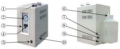
Figure 1
1-- Purified tube
2-- Indicator of working pressure
3 --Water level electrolytic solution
4-- Nitrogen digital flow indicator
5-- Switch of power supply
6-- Liquid bucket of electrolytic solution
7-- Inlet port of air
8--Outlet port of nitrogen
9--Cable of power supply
10--Evacuation valve
3. INSTALLATION AND OPERATION
3.1 Preparation before the operation
3.1.1 Take the instrument out from the packing box. Check if there is any damage on the instrument during the transportation and verify that all of spare parts are provided with the main unit according to the packing list.3.1.2 Adding the electrolytic solution
l) Take out the potassium hydroxide from the spare parts and put them all into a container, then add secondary distilled water or de-ionized water of 500ml as the master solution and fully mixes it. It can be used soon after the electrolytic solution cooling down.
2) Open the outer cover of the liquid bucket of the instrument and take the inner cover out from it.
NOTE: The inner cover is mainly used to avoid the liquid leakage during the transportation. It must be taken out during running. Please keep it well for next transportation.
3) Put the electrolytic solution after cooling down into the liquid bucket, then again continuously add the secondary distilled water or de-ionized water. But it can neither exceed the upper limit water level line nor be lower than the low limit water level line. Screw up its outer cover again. It can be used after ten minutes.
3.2 Self checking of instrument (Never connect with gas chromatograph)
3.2.1 Take off the sealing nut located on the outlet of the air supply and inlet of the nitrogen generator.NOTE: Please keep it well for next usage. Both should be well connected without the gas leakage by a gas tube of Φ3mm.
3.2.2 Firstly switch on the air supply, the moment the pressure meter of the air supply goes up, and the pressure of the nitrogen generator also gradually goes up with the air pressure. When the air pressure reaches up to 0.4Mpa, the nitrogen pressure reaches nearly to 4kg/cm2 (about 0.4Mpa), then again switch on the power supply of the nitrogen generator. Open the evacuation valve for a certain period, the moment the nitrogen digital flow meter should display the digits in the range of 300-350.Close the evacuation valve afterwards, the pressure indicator in five minutes should show 4kg/cm2 (about 0.4Mpa), the digital flow meter will gradually drop to below“030”.That shows the instrument works in normal case. The self-checking is qualified.
3.3 Operation of instrument (Connect with the gas chromatograph)
3.3.1 Take off the sealing nut located at the outlet port of the rear of the nitrogen generator.(Please keep it well for the next usage).
3.3.2 The outlet port of the nitrogen generator qualified after the self-checking is connected with the nitrogen inlet port of the gas chromatograph by a gas tube of Φ3mm.Carefully screw up the nut to be sure for good seal.
3.3.3 Firstly switch on the air supply, then switch on the nitrogen generator and open the evacuation valve at the same time to evacuate running for 20-30 minutes (for guarantee the purity of the nitrogen gas), afterwards screw up the evacuation valve to start running. The evacuation running must be made for 20-30 minutes for each time when the instrument is switched on.
3.3.4 Great attention should be taken to that the flow display must be in accord with the flow display of the gas chromatograph. When the flow displayed exceeds more than the actual flow used by the gas chromatograph, stop the instrument running and verify the gas leakage carefully. Please refer to the sections of troubleshooting. After so, the self-checking is made 3.3.5 Switch off the power supply after the operation for each time, but open the evacuation valve without closing unless the next operation is started after evacuating running for 20-30 minutes. Please pay great attention to this point.
3.3.6 There are two filters filled in color changing silica gel and molecular sieve provided with the instrument. Observe through the viewed window if the color of the silica gel in the filter has been changed. If it is so. please immediately make the replacement or regeneration. Its method shows as follows: Rotate off the filter and loose the top cover of the filter. Again screw it up tightly after replacing the silica. Mount the filter on the chassis and rotate it tightly. After so, verify the gas leakage again.
3.3.7 The electrolytic solution is gradually reduced when the instrument is used for a certain period. The secondary distilled water or de-ionized water should be promptly added when the electrolytic solution is nearly to low limit. Don’t exceed the water level line of the upper limit
when the water is added. The electrolytic solution should be replaced after a half year. (The concentration of the potassium hydroxide used for the nitrogen generator is 10% more or less).
3.3.8 The nitrogen generator can be never run unless the air supply is connected, otherwise the whole instrument will be worthless.
3.3.9 Don’t detach and open the electrolytic cell by user so as to avoid the instrument running in abnormal case.
3.3.10 The electrolytic solution in the liquid bucket must be cleaned up by an ear ball, screw the outer cover tightly when the inner cover is mounted to avoid residual electrolytic solution splitting out during the transportation.
4. WORKING PRINCIPLE AND FEATURES OF INSTRUMENT
4.1 Working principle:
The electric catalyzing method is utilized to process the air separation. The electrolytic cell is designed according to the reverse process of the combustible battery. When the feed air of stable purification is entered into the electrolytic cell, the oxygen in the air is absorbed at the cathode and obtain the electrons, then the oxyhydrogen ion is created due to the reaction of the electrons with water and move it to the anode. At last, the electrons are all lost at the anode and evolve the oxygen. Therefore the oxygen in the air is continuously separated while the nitrogen is only remained. Afterwards it is output by passing through the gas piping.4.2 Features of instrument
4.2.1 Program control: The specialized chip is used in the control system of the instrument. All working process of the instrument will be completed by the program control. The automatic constant voltage, constant current and nitrogen flow can be automatically adjusted in the range of 0-300ml according to the requirements.4.2.2 Process advantage: The electrolytic cell adopts dual cathodes of vertical single liquid level.
PCAN carrier and noble metal catalyst are used on the catalytic layer in order to make the catalyzed capability of the electrolytic cell high efficiency, big gas production and high purified nitrogen. The performance of the electrolytic cell and working status are all very stable due to 4.2.3 Forced circulation: Forced circulation of electrolytic solution. The dissipating heat of the
electrolytic cell should be in a good status during running. The electrolytic solution will be fully returned to the liquid bucket after stopping the operation; therefore the over-liquid phenomenon is effectively avoided.
4.2.4 Three stage catalysis: There is the three stage catalysis providing in exception with two stage catalysis. The new type noble metal is selected as the catalysate, so the oxygen content is less 3ppm.
4.2.5 Low humidity of nitrogen production: The separating technique of the super molecular permeable film and effective de-humidity device are used in the system, so the original humidity is more reduced and automatically drain out the water after closing down. The nitrogen purity is more increased due to using the de-humidity of the metal polymer and bipolar absorption.
4.2.6 Easy operation: Only switch on the power supply if the nitrogen is required. It can be used continuously or at intervals, the nitrogen production is very stable without the attenuation.
4.2.7 Safe and reliable: The safe device is equipped with the system, sensitive and reliable.
5. TROUBLING SHOOTING
5.1 Problems: The instrument does not work.Possible causes: No connection to the circuit Checking area: Test the circuit
Solution: Repair power supply
5.2 Problems: Nitrogen production flow displays less 300 Possible causes: Needle valve is blocked
Solution: Rotate needle valve counter-clockwise, so the valve displayed will be 300 more, then rotate the needle valve clockwise, the value displayed should be stable between 300-350(under evacuation status)
Location: Up part of evacuation value between two filers
5.3 Problems: Nitrogen production can’t reach to resetting pressure.
Possible causes: 1. Gas leakage in gas piping system.
2. Filter and top cover of filter have not be screwed tightly.
3. Reverse current of electrolytic cell.
Checking area 1.Test it by test leakage liquid
2.Verify the connection of gas piping.
Solution: 1.Screw up the gas leakage point tightly.
2. Replace components of gas leakage
3. Electrolytic cell can never be repaired by user self
5.4 Problems: Flow indicator gradually drops down to zero”0”or black screen.
Possible causes: 1.No circulation of electrolytic solution. 2. Switch of power supply is damaged.
3. Indicator is damaged.
Checking area: 1. Observe fluid tube of liquid bucket if there is liquid flowing. If it is not so, that shows cycling pump is blocked or damaged.
2. Measure voltage at both ends of electrolytic cell to check if it is 1.5V more or less using an universal meter.
Solution: 1.Use the ear ball (with stainless steel tube of Φ4) to suck liquid, then aim at water outlet below liquid bucket to squeeze it physically for times.
2. Replace cycling pump.
3. Replace the switch of power supply.
4. Replace the indicator.
Location: Cycling pump is located in the main unit.
6. MAIN TECHNICAL PARAMETERS
6.1 Nitrogen purity: Oxygen content<3ppm, Water content dew point -56℃6.2 Nitrogen flow: 0-300ml/min (Status: 0.4 Mpa)
6.3 Output pressure: 0-4Kg/cm2 (Depends on the pressure of feed gas)
6.4 Pressure stability: <0.003Mpa
6.5 Power supply: 220V±10%, 50Hz
6.6 Consumption power: 60W
6.7 Ambient temperature: 1-40℃
6.8 Relative humidity: <85%
6.9 Outer dimension: 370×330 ×l80mm
6.10 Net weight: About 13 Kg
7. PACKING LIST
| 7.1 BGEN-602 Nitrogen Generator 1 set |
| 7.2 Spare parts |
| 7.2.1 Suction ball (With Φ4 stainless tube) 1 set |
| 7.2.2 Seal ring for filter (Φ14×2.4) 2 pieces |
| 7.2.3 Seal ring for filter (Φ26×2.4) 2 pieces |
| 7.2.4 Seal ring for filter (Φ32×2.4) 2 pieces |
| 7.2.5 Seal ring for gas pipeline (Φ6×1.9 or Φ6×5) 10 or 5 pieces |
| 7.2.6 Screw nut (M8×1) 2 pieces |
| 7.2.7 Potassium hydroxide (analytical purity) 150g/bottle 7.3 Copper gas tube (Φ3) 2m |
| 7.4 Operation Manual 1 copy |