


Drying Oven BODR-7003
- Sea, Air, Door to Door Shipping
- 1 Year Warranty
- US & European Standards
- Polished stainless-steel chamber, semicircular arcs at corners for easy cleaning, and the space between the shelves in the chamber is adjustable
- Auto-controller of fan speed to prevent damage to the samples
- Large LCD screen to display more data at same time
- Self-check function easy to identify problems
Specification
Features
| Capacity | 150 L |
| Electrical requirement | 220 V 50 Hz |
| Controller | Programmable LCD display |
| Power Consumption | 1550 W |
| Temperature Range | RT +10 - 250°C |
| Display Resolution | 0.1°C |
| Temperature Stability | ±1°C |
| Temperature Uniformity | ±2.5% |
| Shelves | 3 pcs |
| Interior Dimension | 500Wx380Dx750H mm |
| Exterior Dimension | 655Wx715Dx980H mm |
| Timing Range | 0~5999 min |
- Polished stainless-steel chamber, semicircular arcs at corners for easy cleaning, and the space between the shelves in the chamber is adjustable
- Auto-controller of fan speed to prevent damage to the samples
- Large LCD screen to display more data at same time
- Self-check function easy to identify problems
- Over temperature and temperature difference alarms
- There is a 25mm instruction connection hole on the left side of the chamber for easy testing operation and temperature
- Programmable controller: 7 periods 63 steps, 0~5999min for each periods, fan speed 0 to 100% adjustable
- Independent audible and visible temperature-limiting alarm system ensures experiments run safely
- RS485 connector can connect computer and printer to record the parameters and the variations of temperature
Operating Manual for BODR-7003
1. Instructions for Safety
2. Product Profile
2.1 Outlook
2.2 Brief of Operating LCD Controller
2.3 Operation steps
2.4 Ways to improve the accuracy of temperature control
2.5 Function parameter table
2.6. Usage of“ Over-temperature Protector” (optional)
3. Maintenance and Instructions
4. Appendix
Packing List
1. Instructions for Safety
! Dangerous (possible to cause serious loss to properties or injuries to personages)1. The Product must be safely grounded (make sure not to use the ZL or neutral line as the earth wire).
2. Before, make sure that the power supply has the voltage in compliance with the requirement of the Product.
3. For the Product, a separate power socket should be used and make sure the plug and socket is properly grounded.
4. With the production running, it is not allowed to pull out and plug in the power plug at random without turning off the power switch.
5. Random extension or cutting of the product’s power cable is prohibited.
6. No inflammable, explosive, evaporative and corrosive articles will be placed in for drying.
7. With the product running at a high temperature of above 80 ℃, don’t touch the box door, vision-light door and surrounding surface to avoid any scald.
8. Don’t place hands or articles into the air inlet or outlet.
9. Unauthorized repair is not allowed and such authorized repair should be carried out by the special personage.
! Warning (Unauthorized repair may cause losses to properties or injuries to personages at one’s responsibility)
1. Make sure to read and understand thoroughly the Product’s Operating Instructions before the operation may be carried out.
2. To take out the power plug, make sure not to pull directly the power cable.
3. In case of any one of the following circumstances, make sure to take out the product’s power cable:
3.1 To change the fuse tube.
3.2 Pending for checking and repair in case of any breakdown with the product.
3.3 The product will not be used for a long period of time.
3.4 To shift the product.
4. With the product switched on, make sure to turn on the fan and use the up difference alarm.
! Attention (Without doing so, it may influence the lifetime and cause the normal operation of the product)
1. The product should be located on the solid and hard surface to keep it in a horizontal mode.
2. Keep certain space around the product.
3. The product must be used in certain conditions.
4. Avoid opening or closing the box door heavily, otherwise doing so will cause the falling of the box door, damage to the product and injury accident.
2. Product Profile
2.1 Outlook
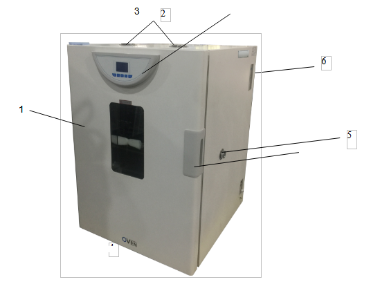
Figure 1
(1) Box Door
(2) Damper Regulator
(3) Display Penal of Thermal Controller
(4) Door Handle
(5) Test Hole
(6) Power Switch
2.2 Brief of Operating LCD Controller
1. Preparations before operationThe product should be operated in the following conditions:
1.1 Ambient temperature: 5℃~40℃,
Relative humidity not bigger than 85%.
1.2 No intense vibration source and strong magnetic field nearby.
1.3 The product should be placed steadily and horizontally in a room without dust, direct sunshine or corrosive gas.
1.4 Sufficient space should be left around the product as shown in the right figure above and not be placed below the fire alarm.
1.5 For power voltage of the product, refer to technical indicators.(Table 1)
1.6 The product should be placed rationally with adjustment to the position and quantity of shelf unit, into which working articles are put. Sufficient space should be left up and down and all around. (>100mm)The weight should be such as not to bend or deform the shelf unit.
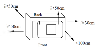
Figure 2
2. Power on
2.1 Close the door of the box, the handle should be vertically downward.
2.2 Turn on the power and the indicator light is on.
2.3 The controller enters the working mode after about 4 seconds of self-checking procedure.
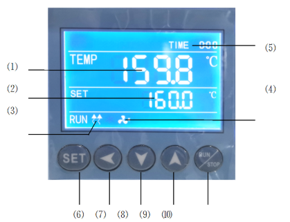
Figure 3
2.4 Indicator light description.
1) TEMP area (PV): display the measured temperature.
2) SET area (SV): display the set temperature.
3) Heating lamp: the lamp is on when there is heating output.
4) Fan indicator light: on when there is fan output.
5) TIME: Time display window; display running time or parameter value.
2.5 Button description
6) SET button: used to modify the set value or enter the internal parameter setting, in the parameter setting state, long press the set button for more than 3 seconds to exit.
7) Shift key: used to shift the set value, internal parameters and view the ambient temperature.
8) Decrease key: used to modify the set value, various parameters, or start/stop auto-tuning.
9) Increase key: used to modify the set value, internal parameters, or view the remaining period (X)
10) RUN/STOP: Press for 3 seconds to run or stop the controller.
2.6 Check temperature control accuracy
2.6.1 Select a digital thermometer with a resolution of 0.1℃ that has passed the verification and is within the verification period as a standard and put it into the product work room, and ensure that the sensor temperature sensor is in the geometric center of the work room.
2.6.2 Choose a point within the temperature control range of the product and set the SV temperature control value. When the PV measurement value is equal to the set value, keep it at a constant temperature (1~2) hours or so (depending on the product specifications, the constant temperature time may vary) , Observe that the difference between the actual measured temperature value of the standard thermometer and the measured value displayed by the controller PV should be ≤±0.5℃.
2.3 Operation steps
1) Temperature setting: Press the "SET" button once, the value of the SET window flashes, indicating that the temperature can be set as required, and the required temperature can be set through the "increase", "decrease" and "shift" keys. Press the "SET" key again to return to the standard display mode.2) Timing function: Press the "SET" button twice, when the time is set to 0, there is no timing function; when the time is set to 0, the controller has a timing function, press the "SET" button, the TIME value flashes, indicating the time can be set as required. Use the "increase", "decrease" and "shift" keys to set the required time value. When the time is up, the TIME window displays the "END" buzzer, and you can press any key to silence it.
Note: ① Each time you modify a parameter, you need to press the "SET" key to confirm and the modification is effective.
② After setting all the parameters, press the "RUN/STOP" key and wait for about 3 seconds to start running.
2.4 Ways to improve the accuracy of temperature control
2.4.1 After the product has been used for a period of time, the temperature control accuracy should be checked according to the method 2.6, if it exceeds ±1℃, it can be corrected according to the following method:2.4.1.1 Enter the parameter setting, find the
 symbol.
After the formula is calculated, it shall be modified on the basis of the original PK value at the time of delivery (Note: One correction is not accurate, and the correction can be repeated until it meets).
2.5 Function parameter table
In the standard state, press the SET key and the shift key at the same time for more than 3 seconds, the LCD screen displays the LK code, and you can enter the password setting level interface.1)When LK is displayed in the output area of the LCD screen, press the plus or minus key or the shift key to make LK=0000, and press the SET key to enter the user parameter level setting.
| Symbol | Name | Setting range | Description | Factory set value |
| Pn | Work group in operation | 0~8 | For program control only. To set up the work group for operation of meters. When Pn is set as 8, Group 8 is for fixed value control. | Optional |
| Cy | Number of cycle in a period | 0~99 | Special parameter for program control. When CY is 0, the meter will run between the work group all the time. When CY is not 0, the meter will shut down automatically after CY in the group. | Optional |
| dy | Appointment boot selection | 0-99::59 | 0: No appointment; for other values, after pressing the run key to start, it will automatically delay the dy time and then start the machine. | |
| ut | UV time | 0-200 minute | Turn off the UV lamp after ut time, ut=0, turn off the UV lamp manually. | Optional |
| uS | UV switch | 0-1 | 0: Turn off the UV light 1: Turn on the UV light. | Optional |
Table1
2)When LK is displayed in the output area of the LCD screen, set LK=0003, and press the SET key to enter the equipment manufacturer's parameter level setting.The parameter hierarchy menu of the equipment manufacturer is as follows:
| Symbol | Name | Setting range | Description | Factory set value |
| tM | Setup of maxi temperature permissible by the instrument | full range | Stop heating beyond maxi temperature and give alarm. | |
| Po | Boot mode | 0~2 | ①When PO =0, after open the power, the controller in a stopped state, by long press star/stop key is up and running. ②When PO =1, after open the power, the controller will be running. ③When PO =2, running from last power began to run. | |
| AL | Setup of alarm | 0~100.0 | When the temperature exceeds the value of SP+AL, the alarm light is on and the alarm is output (with HOLD function). | |
| Pb | Zero adjustment (intercept) | -100.0~100.0 | When the zero error of the instrument is greater and the full scale error is smaller, the value should be adjusted. As a rule with Pt100 the value is seldom adjusted. | |
| PK | Adjustment of full scale (slope) | -1000~1000 S | When the zero error of the instrument is smaller and the full scale error is greater, the value should be adjusted. PK=4000 × (specified value-actual display value)/actual display value and as a rule with Pt100 the value is adjusted first. | |
| PA | Onboard room temperature sensor correction | -30-30 | When there is an error between the on-board room temperature sensor and the actual situation, adjust the value. | |
| 2b | The second zero correction | -100-100 | When the second channel zero error is large and the full scale error is small, adjust this value. Generally, Pt100 rarely adjusts this value. | |
| 2K | Second channel full scale adjustment | -1000~1000 | When the zero error of the second channel is small and the full-scale error is large, adjust the value. PK=4000× (mercury thermometer value-display value)/display value, generally Pt100 adjust this value first. |
Table 2
※The products have been strictly tested before leaving the factory. When the technical indicators meet the requirements and work normally, no correction is generally required.
2.6. Usage of“ Over-temperature Protector” (optional)
The over temperature protector is a separate protection system. When the temperature controller encounters malfunction and causes temperature out of control and when the temperature in the working room reaches the set value, the overheat protector will cut off the heating and initiate the alarm.(See Fig. below)working room temperature is lower than set temperature limit The protection system is released after set value and the meter is restored. Cycle repeats until problem is solved.
6.1 Set value is higher or equal to (SV+AL)+ (10~15)℃
6.2 See Fig. 6, Use + and — button for over temperature setting on control panel.
To set desired temperature limit.
Example: SV=130℃, AL=10
Set the over temperature to 150℃.
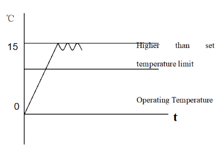
Figure 4
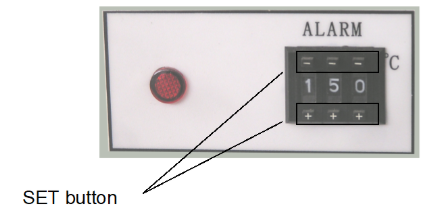
Figure 5
3. Maintenance and Instructions
1. Upon completion of each operation, first switch off the power. Open the box door and wait till the temperature is cooled down in the box before taking out the cultivated goods.2. In case of keeping the product idle for a long period of time, it is necessary to clean the product in and out. Pull out the power plug and cover it with the plastic anti-dust cap.
3. If the environment for storage has a high humidity, it is necessary to regularly (about 1 month) power on for heating to dehumidify.
4. Before using it again or in case of any change in technical requirement, it is necessary to check the accuracy of thermal control (see the relevant sections).
5. Except for change of such parameters as SV, AL, Pk, Lk, to change other control parameters, it is necessary to obtain consent from our Service Center or such parameters can be adjusted by the special personages.
4. Appendix
1. Technical IndicesThe product is produced as per corporate standard Q/TIWY 2-2004
| Sr. No. | Model Index | BODR-7001 | BODR-7002 | BODR-7003 | BODR-7004 | BODR-7005 | |
| 1 | Power Supply Voltage | 220V 50-60 Hz | |||||
| 2 | Thermal Control Range | RT+10-250℃ | |||||
| 3 | Temperature Resolution | 0.1℃ | |||||
| 4 | Fluctuation | ±1℃ | |||||
| 5 | Chamber size (mm) | 350*300*400 | 400*320*550 | 500*380*750 | 600*450*900 | 1000*510*800 | |
| 6 | Bearing Shelf | Two pieces | Three pieces | ||||
| 7 | Input Capacity (W) | 850 | 1100 | 1550 | 2050 | 3000 | |
Table 3
2. Reasons and Handling of Breakdowns
| Description of Breakdown | Assumption of reasons for breakdown | Method for troubleshooting. |
| No power supply upon start-off (the indicator is lit) | There is no electricity at the power socket or the plug cable is not well connected | Repair. |
| The box’s power cable is broken or the plug is not properly connected | Repair or re-plug. | |
| Power switch is out of order (or not on) | Replace or turn on the power switch. | |
| Fuse is burnt out | If it burns out again after replacement, it is necessary to check if the switch, motor, heater, thermal controller and parts any short-cut or leakage (with insulation resistance being 0) and repair before re-start. | |
| Meter displays “□□□□” | Sensor is out of order or cable is cut (off) | Repair or replace Pt100. |
| No heating | Error in time setting | ST≠0 or “ST≠ (heating + constant temperature + cultivation) minute. |
| Thermal controller is out of order (without output) | Replace. | |
| The dual-way silicon control is not connected | Replace (Model: BTA16 or BTA26). | |
| The heating tube’s connection is off or short-cut | Repair or replace. | |
| Inaccurate thermal control (big steady-state error) or heating up out of control (buzzer beeps) | Heating graph is not lit and the temperature rises | Replace the silicon control out of order. |
| Fan is out of order (not running) | Turn on or replace the fan. | |
| The ambient temperature has excessively small temperature difference with the set temperature | Minimum thermal control temperature: RT+10℃. | |
| Pt100 is not properly connected and the resistance value becomes bigger | Reconnect. | |
| Ar, P and other parameters are not properly set | Re-set. | |
| Pb and Pk are not accurately adjusted | Regulate the set Pb, Pk. | |
| Abnormal or big noises | The fan’s bearing is out of order and lacks lubricant oil | Add lubricant oil or change the fan. |
| In friction with the rear air-duct penal | Repair (or place the washer). |
Table 4
Packing List
Product Name: High-temperature Dry Oven| No. | Type | Item | Unit | Quantity | Remarks |
| 1 | Document | User Manual | 1 | ||
| 2 | Document | Packing List | share | 1 | |
| 3 | Accessories | Shelf board | pcs | 2 | BODR-7003/BODR-7004 3 pieces |
Packaging list conforms to articles in the package
Packed by: 2 Tested by: 1