Get Quote ▼
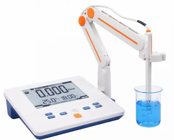
Conductivity Meter BMET-302
 Get Quote
Specifications
| Model | BMET-302 |
| Conductivity | |
| - Range | 0.00 μS/cm to 200 mS/cm |
| - Resolution | 1.01 μS/cm minimum; changed with range |
| - Accuracy | ± 1.0 % FS |
| - Reference Temperature | 25 °C |
| - Standard Recognition | 84 μS/cm, 1413 μS/cm, 12.88 mS/cm |
| TDS | |
| - Range | 0.00 mg/L ~100 g/L |
| - Resolution | 0.01 mg/L minimum; changed with range |
| - Accuracy | ± 1.0% FS |
| Temperature | |
| - Range | -5 to 110 °C, 23 to 230 °F |
| - Unit | °C |
| - Resolution | 0.1 |
| - Accuracy | ±0.2 |
| Measurement | |
| - Reading Mode | AutoRead, Continuous |
| - Reading Prompts | Reading, Stable, Locked |
| - Temp. Compensation | ATC, MTC |
| Data Management | |
| - Data Storage | 50 results each |
| Inputs | |
| - Temp./EC. Probe | 5-pin aviation connector |
| Display Options | |
| - Backlight | Yes |
| - Auto Shutdown | 300, 600, 1200, 1800, 3600sec, off |
| - IP Rating | IP54 |
| General | |
| - Power | AC Adapter, 100-240 V AC |
| - Dimensions | 242 x 195 x 68 mm |
| - Weight | 900 g (1.98 lb) |
Operating Manuals
 Download Manual (PDF)
1. Introduction
1.1 Introduction
1.2 Technical Specification
1.3 Function Introduction
2. Safety Notices
3. Terms Explanation
4. Overview and Installation
4.1 Overview
4.2 Instrument Installation
5. Instrument Operation
5.1 Screen Icons
5.2 Key Function
5.3 Instrument Settings
5.4 Electrode Calibration
5.5 Measurement
6. Maintenance/Troubleshooting
6.1 Maintenance
6.2 Electrodes Maintenance
6.3 Troubleshooting
7. Technical Supports
1. Introduction
1.1 Introduction
BMET-302 Conductivity Meter can measure conductivity and TDS in water solution, and can be widely used in universities, environmental protection, medicine, food, sanitation, geological prospecting, metallurgy, ocean exploration.
• General Features
• High resolution LCD display screen, 6.0 inches.
• It can measure conductivity, TDS and Temperature.
• Multi-reading feature allows auto-read and continuous-read.
• Reading prompts shows the status of reading.
• Cell constant is settable.
• 1 point calibration automatically recognizes the standard solutions, including 12.88mS/cm, 1413μS/cm and 84μS/cm.
• Automatic/Manual temperature compensation ensures accurate results.
• Data storage 50 sets for each parameter.
• IP54 protection.
1.2 Technical Specification
Instrument Specifications
Model | BMET-302 | |
Conductivity | Range | 0.00μ S/cm~200mS/cm |
Resolution | 0.01 μS/cm, automatic switching according to the range | |
Accuracy | ±1.0%(FS) | |
Repeatability | 0.33%(FS) | |
Measurement Accuracy | ±1.50%(FS) | |
Measurement Repeatability | 0.70%(FS) | |
TDS | Range | 0.00mg/L~100g/L |
Resolution | 0.01mg/L, automatic switching according to the range | |
Accuracy | ±1.0%(FS) | |
Temperature | Range | (-5.0~110.0)°C |
Resolution | 0.1 °C | |
Accuracy | ±0.2 °C | |
Instrument indication error | ±0.4°C(0.0°C~60.0°C), ±1.0°C(Else) | |
Work environment | Ambient temperature: (0~40) °C Relative humidity: not more than 85% | |
Dimensions (LxBxH), weight (kg). | 242mmx195mmx68mm, 0.9kg | |
Power supply | AC Adapter,100-240V AC input, DC 9V output | |
Table 1
1.3 Function Introduction
Function | Explanation | |
Basic Function | Backlight adjustment | • |
Reset settings | • | |
Power failure protection | • | |
Anti-interference automatic recovery | • | |
Automatic shutdown | • | |
Protection | IP54 | |
Reading Function | Default balance settings | • |
Auto-lock reading | • | |
Reading Mode | auto-read and continuous-read | |
Data Management | Storage | 50 sets |
View | • | |
Delete | • | |
Measurement | Conductivity | • |
TDS | • | |
calibration point | 1 point | |
Automatic standard solutions recognition | 12.88mS/cm, 1413μS/cm and 84μS/cm | |
Cell constant set | • | |
Auto temperature compensation | • | |
Manual temperature compensation | (0.0°C~60.0°C) | |
Temperature Function | Temperature Unit | °C |
Table 2
2. Safety Notices
Please read the entire contents of this manual carefully before use, and please keep this manual properly. The user MUST use the instrument following this manual to avoid damage to the user and equipment.
Before using the meter, READ the following notes:
• DO NOT disassemble the device for inspection or repair.
• To prevent electric shock or damage to the device, do not place cables and connectors in any liquid, wet or corrosive environment.
• Please use the defaulted power adapter, Do not use it if the power cord is damaged (the wire is exposed or broken).
• Do not use in flammable and explosive environments.
• Do not use if the user finds any abnormalities such as damage or deformation of the device.
The following identifier will be used in this manual.
 TIPS:
TIPS:
Tips help users to use the meter.
3. Terms Explanation
• Cell Constant: Also known as the conductivity cell constant. The ratio of the distance to the area of the electrode sheet, expressed in cm-1. Usually, there are conductance electrodes with several cell constants such as 0.01, 0.1, 1.0, 10, etc. The conductance electrode with a cell constant of 1.0 is the most used one and has a wide measurement range.
• Temperature Coefficient: The change in conductivity caused by a 1°C change in temperature is usually expressed in %/°C, and the default is 0.02, which is 2.00%/°C.
• TDS Conversion Factor: The conversion factor between conductivity and TDS, which defaults to 0.5.
4. Overview and Installation
4.1 Overview

Figure 1
Overview-Front View

Figure 2
Overview- Back View

Figure 3
Electrodes and connectors
Connector Specifications
Electrode type | Connector specifications |
Conductivity electrode | 5-pin aviation |
Table 3
4.2 Instrument Installation
4.2.1 Electrode Stand Installation
1) Pull out the plate on the right side of the meter.
2) Insert the electrode holder into the fixed vertical shaft of the plate.
3) Screw the fixed screws at the bottom of the electrode holder.

Figure 4
Electrode Stand Installation
4.2.2 Electrodes Connection
Push the conductivity electrode into the electrode holder. Remove the protector cap of the conductivity electrode. Connect the conductivity electrode into the right socket. Combination conductivity probes integrated with ATC probe.
5. Instrument Operation
5.1 Screen Icons
The meter has 6.0 inches high resolution LCD display screen. The User interface has the menu, status, result and parameter. The menu has measurement, calibration, setting and view. The status shows the reading mode, reading prompts and auto shutdown etc. The result shows the conductivity and unit. The parameter shows manual temperature, data No., cell constant and type.

Figure 5
Screen icons explanation
Symbol Explanation
No. | Symbol | Explanation | Note |
1 |
| Reading state | When all four sections are lit up, it shows a stable status. |
2 | | Reading is locked | In the auto-read mode, when the reading is stable, end the measurement, the result has locked. |
3 |
| Confirm the option | Flashing Display when Need to Confirm |
No. | Symbol | Explanation | Note |
4 |
| Automatic shutdown | |
5 | | Delete the result | |
6 | Sec | Time Unit | Unit: Sec |
7 | mg/L | TDS Unit | Unit: mg/L |
8 | g/L | TDS Unit | Unit: g/L |
9 | μS/cm | Conductivity Unit | Unit: μS/cm |
10 | mS/cm | Conductivity Unit | Unit: mS/cm |
11 | MTC | Manual temperature compensation | |
12 | ATC | Auto Temperature compensation | |
13 | °C | Temperature Unit | Unit: °C |
14 | Const | Cell Constant | |
15 | TDSF | TDS Conversion Factor | |
16 | Type | Electrode Type | |
17 | No. | No. | |
18 |
| Auto-read | Auto reading |
19 |
| continuous-read | Continuous Reading |
20 |
| Measurement | |
21 | | Calibration | |
22 |
| setting | |
23 |
| View |


Table 4
5.2 Key Function

Figure 6
The Screen and the Key
Key Function Explanation
No. | Key | Explanation | Note |
1 | | Power Key | Switch on the meter by press and release the key. Switch off the meter by press and hold the key for more than 3 seconds and release. Backlight adjustment key when Switch on the meter. |
2 | | Mode/Up | Exchange the display of Conductivity and TDS. Increase the number in setting. Browse the data in view. |
3 | | Save/Down | Save the result. Decrease the number in setting. Browse the data in view. |
4 | | setting | Enter into setting when in the measurement status. Adjust the temperature and calibration type. |
5 | | Meas/Del | In the auto-reading mode, measure the next sample. Delete the data when browse. Change to the manual recognitioncalibration in the calibration status. |
6 | | Cal/Enter | Enter into the Calibration status. Identify the operation. |
7 | | Cancel | Give up. |


Table 5
5.3 Instrument Settings
5.3.1 Switch On/Off
Connect the power adapter, and press and release  to switch on the meter. The startup screen shows the device model, name, software version and other related information. After the self-test program, the screen turns to the homepage and the meter are ready to measure. Press and hold the key for more than 3 seconds and release to shut down.
Switch On/Off Interface Explanation
No. | Display | Explanation |
1 | U7A | Switch On, Software Version |
2 | OFF | Switch Off |
Table 6
5.3.2 Instrument Settings
Instrument Settings
No. | Explanation | Note |
1 | Reading Mode Settings | Flashing display |
2 | Cell constant settings | Flashing display Const |
3 | TDS Coefficient Setting | Flashing display TDSF |
4 | Temperature Settings | Flashing show °C |
5 | View the data | Flashing display |
6 | Automatic shutdown settings | Flashing display "APD"(Auto Power Down) |
7 | Reset settings | Flashing display "rSt" (Reset)and "dFt" (Default) |
Table 6
he meter has the parameter setting, such as Reading Mode Settings, Cell constant settings, Temperature Settings, View the data, Automatic shutdown settings, and Reset settings. Press the "Setting", the meter shows the setting symbol, SEL and number. Press the up and down to adjust the parameter and press "Enter" to select.

Figure 7
Instrument Settings
5.3.2.1 Reading Mode Settings
The meter provides two reading modes, including continuous readings, and auto reading.
• Continuous reading: The instrument displays real-time measurement results. User can end the measurement at any time and save the last result.
• Auto-reading: The measurement reached the balance, and the meter locked the reading result. Balance condition is that the results fluctuates within 0.4% for 6 sec. In the auto-reading mode, press the "Meas" to test the next one sample.


Figure 8
Continuous reading and Auto-reading Display
TIPS:
In the measurement status, press and hold "Meas" for more than 3 seconds and release to exchange the reading mode.
5.3.2.2 Cell Constant Settings
Please refer to 5.4.2.
5.3.2.3 TDS Coefficient Settings
The TDS coefficient can be adjustable, and the default is 0.500.
In the measurement status, press the "Setting" to select the TDS Coefficient Setting, and press the "Cal/Enter" to adjust the coefficient, then press "Cal/Enter" to save the TDS Coefficient.press "Cal/Enter" to save the TDS Coefficient.

Figure 9
TDS Coefficient Setting
5.3.2.4 Temperature Settings
The meter supports auto temperature compensation and manual temperature compensation.
When select manual temperature compensation function, it needs to use the EC electrode without temperature measurement. Measure the test solution temperature with the temperature meter. Press "Setting" to select the "Temperature setting", then press "Cal/Enter" to adjust the temperature as the real temperature, press the "Cal/Enter" to save the temperature.

Figure 10
Temperature Settings
5.3.2.5 View the data
The meter provides 50 sets of measurement results storage space.
In the measurement status, press "Setting", select the view, press "Cal/Enter" to browser the data. Press the "Mode/▲" and "Save/▼" to view the data and number. In the view status, press "Setting" to exchange the display of Conductivity and TDS.

Figure 11
The data information
It offers single deletion and all deletion. dELonE 1 means single deletion and dEL All 2 means all deletion. Press the up and down to select the delete type and press the "Cal/Enter" to delete data.
TIPS:
➤ In the measurement status, press the "Save/▼" for 3 sec to enter view to browser data.
➤ The "nuLL" means Null Stored Result in the View Interface.
5.3.2.6 Automatic shutdown settings
The meter provides auto shutdown function. When the meter is not using and set the auto shutdown, the meter switches off automatically. There are six options: off, 300Sec, 600Sec, 1200Sec, 1800Sec, and 3600Sec.
5.3.2.7 Reset settings
When the meter is not working. Users can reset the meter from the default's backup. The default setting includes constant type as 1.0, Cell constant as 1.000, refer temperature as 25.0°C, continuous reading mode, automatic shutdown as close etc. All data will be deleted after resetting.
5.4 Electrode Calibration
5.4.1 Conductance Electrode Preparation
In common, there are two type calibrations. one is entering the cell constant value directly; the other is calibrating the conductance electrode with standard conductivity standard solution.
There are many conductance electrodes in order to suit for different measurement range. According to the material, conductive electrode is divided into platinum black electrode and bright electrode. Usually, there are conductance electrodes with several cell constants such as 0.01, 0.1, 1.0, 10, etc. The conductance electrode with a cell constant of 1.0 is the most used one and has a wide measurement range.
It is needed to select the suitable conductance electrode according to the sample properties, such as the conductivity range as recommend table.
Conductivity Range and Cell Constant recommend
Cell constant cm-1 | Conductivity range μS/cm |
0.01 | 0~2.000μS/cm |
0.1 | 0.2~20.00 μS/cm |
1 | 2 μS/cm~100.0 mS/cm |
Table 7
5.4.2 Cell Constant Settings
Users need to enter the cell constant value on the label of conductance electrode for accurate measurement. The defaulted conductivity cell constant is 1. Cell constant settings process is as follows:
1) In the measurement status, press "Setting" to select the Cell constant settings, press "Cal/Enter" to adjust cell constant and type.
2) Adjust the constant type by press the "Setting".
3) Adjust the cell constant by press the "Mode/▲" and "Save/▼".
4) Press "Cal/Enter" to save the constant.

Figure 12
Constant Type is 1.0, Cell constant is 1.000

Figure 13
Constant Type is 1.0, Cell constant is 0.998

Figure 14
Constant Type is 0.1, Cell constant is 0.998
5.4.3 Calibration with Standards
In general, conductivity electrodes need few calibrations. When the user gets an unexpected result, an electrode calibration is considerable.
Usually, single standard solution is required for calibration. The meter supports one point calibration. The standard solution needs close to the sample.
Calibration Interface Explanation
No. | Display | Explanation |
1 | Auto | Auto Standard Recognition |
2 | Non | Manual Standard Recognition |
3 | Err | Calibration Failure |
4 | OH | Calibration success |
5 | End | Calibration End |
Table 8
The meter supports auto standard recognition includes 12.88mS/cm, 1413μS/cm and 84μS/cm.
For conductivity electrodes with different cell constants, it is recommended to use the following conductivity standard solutions for calibration.
KCl standards to electrode cell constants
Cell constant (cm-1). | 0.1 | 1 | 10 |
KCl solution Concentration (mol/L). | 0.001 | 0.01 or 0.1 | 0.1 or 1 |
Table 9
Approximate concentrations of KCl solutions and their conductivity values relationship
T(°C) | 84μS/cm | 1413μS/cm | 12.88mS/cm |
5 | 53.02 | 896 | 8.22 |
10 | 60.34 | 1020 | 9.33 |
15 | 67.61 | 1147 | 10.48 |
20 | 75.80 | 1278 | 11.67 |
25 | 84.00 | 1413 | 12.88 |
30 | 92,19 | 1552 | 14.12 |
35 | 100.92 | 1696 | 15.39 |
Table 10
The auto standard recognition calibration process is as follows:
• Place a standard conductivity (e.g., 1413μS/cm conductivity solution) solution in a thermostatic bath, and set the temperature to (25.0±0.1) °C.
• Rinse the conductance electrode with DI water, dry out and place it into a standard solution.
• Press the "Cal/Enter", enter the Calibration status.
• Press "Setting", adjust the temperature(25.0°C), then press "Cal/Enter" to save the temperature.
• When the conductivity and temperature reading (e.g.1420μS/cm, 25.0°C)are stable, press "Cal/Enter" to end the calibration.
• The meter automatically saves calibration data and shows the calibration results (e.g.1413μS/cm, 25.0°C).
• After calibration complete, the meter turn to the measurement status.
If use other standard solutions to calibration, it needs to know the relational table of conductivity and temperature.
The manual standard recognition calibration process is as follows:
• Place a standard conductivity (e.g., 1413μS/cm conductivity solution) solution in a thermostatic bath, and set the temperature.
• Rinse the conductance electrode with DI water, dry out and place it into a standard solution.
• Press the "Cal/Enter", enter the calibration status.
• Press "Meas/Del" for 3 second. The meter shows the "Non" in the display. It changes to manual standard recognition status. Adjust the conductivity standard value manually.
• Press "Setting", adjust the temperature, then press "Cal/Enter" to save the temperature.
• When the conductivity and temperature reading are stable, press "Cal/Enter" to end the calibration.
• The meter automatically saves calibration data and shows the calibration results.
• After calibration complete, the meter turn to the measurement status.
5.5 Measurement
5.5.1 Measurement Preparation
Before measurement, the user should understand the properties and attributes of the substance (sample) to be measured; the method of routine testing; know the basic operation and application of the instrument; know the use and maintenance of conventional electrodes.
The user needs to prepare the sample first, or the standard solution that needs to re-calibrate the electrode, etc.
5.5.2 Measurement
The meter provides conductivity and TDS measurement, it could exchange by pressing "Mode/▲" in the measurement status. Before TDS measurement, please identify the Electrode Type, the cell constant and TDS conversion factor are set correctly.
The meter provides two reading modes, including continuous readings, and auto readings. It could select the reading mode according to the actual situation. When it needs to monitor the conductivity value constantly, please select the continuous reading mode.
The measurement process is as follows:
• Rinse the electrode with DI water. Put the measurement end of the electrode into the sample solution.
• When the reading (Conductivity/TDS, Temperature) is stable, end the measurement.
• Press "Save/▼"to record the results if necessary.
• If in the auto reading mode, the measurement reached the balance, and the meter locked the reading result. It shows the locked mark and the data will not change until pressing the measure to test the next one.
• After measurement, switch off the meter, and store the probe referring to the electrode instruction manual.
6. Maintenance/Troubleshooting
6.1 Maintenance
The correct use and maintenance of the instrument can ensure the accurate and reliable performance of the instrument. Additionally, exposure to chemicals or harsh Work environments can affect performance.
• If the meter is not used for a long time, please disconnect the power supply.
• The electrode socket of the instrument must be kept clean and dry, and should not be in contact with acid, alkali, and salt solutions.
• Keep the meter and accessories clean and away from acids, alkalis, and any corrosive solutions/gases.
• Users can clean the meter surface with clean waters and detergent.
• When the meter is transported, please follow the instructions:
• please remove all connected cables.
• Please remove the electrode holder.
• Please use original packaging in the long-distance transport to avoid damage.
6.2 Electrodes Maintenance
Before using the electrode, you should read the electrode manual carefully to know the type, structure and application scope of the electrode.
For more detailed information, please refer to the electrode instruction manual.
6.3 Troubleshooting
Phenomenon | Probable reasons | Solutions |
1. No Display | No power supply. Damage to the meter. Damage to the Adapter. | Reconnect to the adapter and switch on. Replace or repair as required. Change the adapter. |
2. Incorrect EC measurement | The electrode is out of service life. The electrodes are not calibrated or are calibrated incorrectly. | Replace the electrodes. Recalibrate the electrode or replace the standard solution. |
Table 11
If the meter still does not work, please contact your local dealer for further assistance.
7. Technical Supports
Accessories
Please refer to the accessories table for purchasing recommendations.
Meter accessories
Name | Description |
DJS-1VTC conductivity electrode | Conductivity, TDS Measurement Probe |
DJS-1VC conductivity electrode | Conductivity, TDS Measurement Probe |
DJS-1VTG conductivity electrode | Conductivity, TDS Measurement Probe |
DJS-1VG conductivity electrode | Conductivity, TDS Measurement Probe |
DJS-0.1VTG conductivity electrode | Conductivity, TDS Measurement Probe |
Conductivity solution 1413μs/cm 250mL | Standard solution |
Table 12