
Get Price
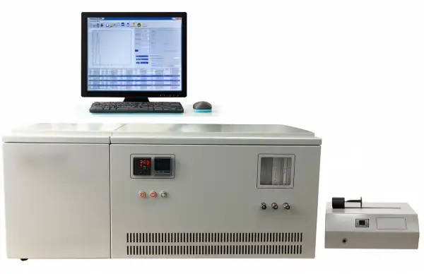
Tester Petroleum Equipment BPTL-403
The instrument is utilized to decide the whole sulfur substance by bright fluorescence method. It improves the capacity of anti-jamming and avoids the complicated operation of titration pool and components of insecurity which utilized Coulometry.
- The instrument is used to determine the total sulfur content by ultraviolet fluorescence method. It Improves the ability of anti-jamming and avoids the complicated operation of titration pool and factors of instability which used Coulometry. So the sensitivity of the instrument is greatly improved. The data collecting, processing, storage and printing are fully controlled by computer.
- Up to 3-Year Product Warranty
- US & EU Compliance Standards
- Door-to-Door Shipping
Technical Specifications
Detailed operating and construction parameters for this model.
| Model | BPTL-403 |
| Sample injection quantity | Solid: 1-20 mg; Liquid: 5-20 μL; Gas: 1-5 mL |
| Determination method | Ultraviolet fluorescence method (S) |
| Measuring range | 5 ppm ~ 5000 ppm (High concentration should be diluted, low concentration gas sample is up to 0.1 ppm) |
| Temperature range | Ambient to 1150°C |
| Temperature control precision | ±1°C |
| Air supply - High purity argon | Above 99.9% |
| Air supply - High purity oxygen | Above 99.9% |
| Power supply | AC220V ±22V, 50Hz ±0.5Hz, 1500 W |
| Dimension - Host | 305(W) x 460(D) x 440(H) mm |
| Dimension - Temp controller | 550(W) x 460(D) x 440(H) mm |
| Net weight - Host | 20 kg |
| Net weight - Temp controller | 40 kg |
| Standard configuration | Printer + Computer + SYD 0689 + Liquid injector |
| Other optional parts | Solid sample injector, gas sample injector |
Product Features
Key design, performance, usability, and safety advantages.
Applications Explore common laboratory, research, industrial, and process applications.
Petroleum Industry, Oil and Gas Industry
Operating Manual View instructions, operating procedures, safety information, and maintenance guidance.
1. Purpose and scope
2. Main technical specification and parameters
3. Working principle and main features
3.1. Working principle
3.2. Main features
4. Main structure
5. Installation
5.1. Installation environment and material needed
5.2. Instrument installation position
5.3 Installation note
5.4 Gas installation and leak
5.5 Quartz pyrolysis tube installation
5.6. Power plug wire and connection wire installation
6. Instrument Software Introduction
6.1. Document processing
6.2. New sample file
6.3. Print test data
6.4.open the standard sample file
6.5.Open the sample file
6.6.Parameter setting
6.7. Operation control
6.8. Exit the application
7. Standard curve making
7.1. Notes to the standard sample confection
7.2. Standard curve making steps
8. Sample analysis
9. Simple Operation Instructions
9.1 The sequence of the instrument powering on
9.2 The sequence of instrument shutting down
10. Common problems and solutions
11. Operation Instruction
11.1 Preparation before the machine powered on
11.2 Power on the machine
11.3 Draft the standard curve
1. Purpose and scope
The instrument is designed and manufactured in accordance with the requirements of the industry standard for the determination of total sulfur content in light hydrocarbons, engine fuels, and other oil products (Ultraviolet fluorescence method).
This instrument is a new generation analysis system to analyze the sulfur content in the liquid, solid and gas material by adopting the ultraviolet ray fluorescence method and combining the computer control technology. This instrument is composed of the new type micro current amplifier, computer control data collecting, and processing and ultraviolet ray fluorescence analysis system. This instrument has the characteristics of high sensitivity, low noise, wide linear range, strong resisting disturbance, stable properties and convenient operation etc, which is widely used in the petrochemical, electronic power, environment protection and the other related science institute and production facility etc.
2. Main technical specification and parameters
1. Testing method: ultraviolet ray fluorescence method
2. Sample condition: solid, liquid and gas
3. Scope: 0.1mg/L~10000mg/L (liquid)
4. Testing limit: 0.05mg/L
5. Repeatability deviation
X≤0.5mg/L, ±0.1mg/L
0.5mg/L < x ≤ 1.0mg/L, Cv ≤ 10%
1.0mg/L<X≤5.0mg/L, Cv≤5%
X>5.0mg/L, Cv≤2.5%
6. Temperature scope and accuracy: room temperature ~ 1200°C 0.5%±1°C;
7. High voltage scope: DC 0V~900V; To set the high voltage value according to the sample concentration
8. Power source: 220V±22V,50Hz±1Hz
9. Power: ≤3KW
10. Outline dimensions: 660㎜x500㎜x400㎜(excluding the computer)
11. Weight: 40kg(excluding the computer)
3. Working principle and main features
3.1. Working principle
The ultraviolet fluorescence oil sulfur tester adopts the principle of pulse ultraviolet fluorescence method; The working principle and gas flow direction diagram are shown in the figure 1

Figure 1
The sample will be introduced into the pyrolysis tube or the sampling boat, and is put at the high temperature combustion tube. With rich oxygen, the sulfide will be converted into SO2; After SO2 irradiated by ultraviolet ray it will absorb the energy of the UV-light and turn into excited state SO2. Upon the excited state SO2 is back to their original state, the excess energy will be released by light which will be received by photomultiplier at specified wave length. The fluorescence amount is specified to the light and is directly proportioned to the sulfur content in the original sample. Through micro current amplifier amplifying and computer data processing, it will convert into the electric signal.When the instrument is used to analyze the sample, the corresponding standard curve needs to be made by the sulphur standard sample first, and the sample will be analyzed based on the standard curve, then the sulphur content will be determined.
Warnings: too much UV-light is not good for health. The tester will try to avoid the damage from the direct shine of UV-light and scattering UV-light, especially to the eyes.
3.2. Main features
3.2.1. Equipped with a desktop computer using the Windows operating system, and complete all parameter settings and tests through direct human-machine dialogue.
3.2.2 Adopting computer control technology to automatically complete data collection, processing, storage, and printing, the testing has a wide linear range and strong anti-interference ability.
3.2.3 Using imported fluorescent excitation sources, membrane desiccants, filters, etc., the testing results have the advantages of high sensitivity, fast, stable, accurate, and consistent.
3.2.4 Adopting an advanced temperature control system, the heating is fast and stable, and the temperature control accuracy can reach 0.5%±1 °C within the full temperature control range.
3.2.5 It can test the sulfur content of liquid, gas, and solid samples, with strong adaptability and wide application fields.
3.2.6 Adopting a modular integrated desktop structure design, the host, computer system, temperature and flow controller, and injector form a whole, which is novel and beautiful.
3.2.7 Need few test samples and the test is fast. It takes about 2 minutes for each sample.
4. Main structure
The instrument is composed of computer system (with software), printer, host machine (with
temperature flow controller), sample injector (as shown in Figure 2).

Figure 2
(1) Host machine (2) Computer system (3) Temperature flow controller (4) Sample injector
1. The host machine can collect the data and amplify. There are power
socket, earth connection,fans and USB port on the rear panel (as shown in Figure 3)

Figure 3
(1) RS232 serial port (2) Network cable interface (3) power line
(4) Vacuum pump power socket (5) Vacuum pump connection pipe interface
2. Temperature flow controller
The temperature flow controller is composed of high temperature cracking furnace and
corresponding control circuit and gas flow controller instruments.
On the front panel of the instrument there are temperature controller, three flow meters for
the cracking oxygen, oxygen and argon introduced and the needle valve to control the gas flow
(as shown in figure 4)

Figure 4
(1) Temperature controller (2) Temperature control switch (3) Fan switch (4) Delay switch
(5) Timing delay device (6) Cracking oxygen (7) Imported oxygen (8) Argon (9) Flow meter
On the rare panel there are the entrance of argon and oxygen; power, fuse base, fans (as shown in figure 4
3. Socket socket

Figure 5
 Attention: When replacing the power socket fuse, be sure to unplug the power line of the power socket to ensure operation in a power off state (5A for the host, 2A for the temperature controlled fan and injector).
Attention: Push the round holes by the screwdriver to see the fuse from the figure of the "back of the power socket" and restore it after the fuse has been replaced.
4.4. Injector
Three kinds of injectors can be used in this instrument: Liquid sample injector, gas sample
injector and solid sample injector. Of which, liquid sample injector is equipped with the instruments,the other two kinds are optional.
4.4.1 Liquid sample injector (see in figure 6)
The liquid sample injector injects the sample automatically by the screw which is drove by the
stepped motor and controlled by SCM. After the sample injected, the screw will be back
automatically. Adjusting two driving plate switches are to setting the progress and speed of the
screw. The process and the speed of the sampling will be set by the detail requirements. This
instrument can inject the liquid sample automatically.

Figure 6
4.4.2 Gas sample injector (Figure 7)
Gas sample injector is to vaporize the sample at a set temperature and make the vaporized sample entering into the tube and push it into the pyrolysis tube.

Figure 7
The gas injector will be operated as the below procedures:
a. Power on the gas sample injector;
b. Switch the temperature controller to set condition and adjust the setting knob. The temperature will be about 60°C~80°C;
c.To switch the temperature controller to sampling condition, the gas expansion room is heated to the preset temperature, it will be balanced at least 20 minutes later;
d. To turn the six-way valves in clockwise and anticlockwise direction several times to ensure the valve open or close freely.
e. To switch the six-way valves to sampling condition and blow the six-way valves at least 15 seconds by the sample gas.
f. To switch the six-way valves into the sample injecting condition quickly;
g. To repeat the step 5, step 6 for continuing measurement otherwise to turn off the sample gas and finish the measurement.
4.4.3 Solid sample injector (Figure 8)
The solid sampling boat will be used if the sample injecting is not suitable for the solid and high boiling point thick liquid sample. To push the sample to the preheat part of the pyrolysis tube by pushing bar. After 5 seconds, the sample boat will be pushed to the heating part to make the sample cracked; the pyrolysis result material will be entered into the quartz tube by carrier gas. Then pull the sample boat to the outlet of the pyrolysis tube for cooling and wait for the second sample analysis.

Figure 8
4.4.5. Membrane dryer (Figure 9)
The material left after the sample combustion in the high temperature pyrolysis tube going
through the membrane dryer to remove the vapor in the sample before reaction, please refer to
Figure 9
Reminder: To guarantee the dehydration effect of the membrane dryer, there are at least two
minutes needed for the interval between two sample injector;

Figure 9
4.4.6.Quartz pyrolysis tube
4.4.6.1 Clean oil quartz pyrolysis tube

Figure 10
4.4.6.2 Heavy oil quartz pyrolysis tube

Figure 11
5. Installation
5.1. Installation environment and material needed
5.1.1 Environment temperature: 5°C ~ 35°C
5.1.2 Relevant humidity: ≤80%
5.1.3 Avoid sharp temperature changes and direct sunlight around.
5.1.4 There is no strong vibration, dust, corrosive gases, strong electric or magnetic field interference around.
5.1.5 Electric Power Source: AV: 220V±22V,50Hz±1Hz; Power≥3KW;
5.1.6 The instrument host and temperature control power supply must be separated, and during installation, it should be avoided to connect the same high-power high-frequency electronic equipment to the same power supply.
5.1.7 The instrument installation should have a good grounding wire, and its resistance to ground should be less than 5 Ω.
5.1.8 High purity oxygen: purity≥99.995%; water content≤5ppm; oxygen reducing valve needs to be prepared;
5.1.9 High purity Argon; purity≥99.995%; water content≤5ppm, argon reducing valve needs to be prepared;
5.1.10 The clean and dry polyfluorotetraethylene pipe or stainless steel pipe will be used for the gas circuit connection pipe.
5.1.11 The suitable desktop needs to be prepared for putting the instrument and the desktop size need to be 700m (W) x 2000mm (L);
Note: For the analysis system is working stable for the long term, the air conditioner needs to be equipped in the operation room;
5.2. Instrument installation position

Figure 12
This position is convenient for the instrument operation individually
5.3 Installation note
5.3.1 The power of the host and the power of the sample injector need to be separated to avoid the interference;
5.3.2 The cracking furnace working temperature will be above 1000°C for Model ZDS-2000A Fluorescence Sulfur Analyzer, it can be regarded as a kindling. The instrument needs to be installed in an environment without inflammable gas.
5.3.3 Power on the instrument after the gas connection wire connected and the air bottle opened.
5.3.4 Poor ventilation will cause the instrument parts overheated and will damage the system parts;
5.3.5 To analyze the effumability sample or inflammable gas (liquefied petroleum gas, Hydrocarbon gas), the air needs to be sure ventilation before the sample to be injected otherwise the whole analysis system needs to be put it in the stink cupboard;
5.4 Gas installation and leak

Figure 13
All the gas sources (carrier gas and oxygen) will be transported by the clean and dry copper or
stainless steel pipe. These pipes need to be rinsed carefully and dried to guarantee the gas will not be polluted. When the new pipe washed, trichloromethane or trichloroethane will be used first, then use methanol or acetone, the air dry will be the last one. The other solvents which can dissolve oil or grease can also be used. All the solvents should be analytical reagent grade or better solvents;All the gas sources shall be the high purity gas and its purity shall meet the system requirements;Each steel bottle needs to be equipped with one two stage pressure regulator, which will make the gas bottle pressure low to the required work pressure. To check the system carefully for the leak and ensure the gas circuit complete after all the gas adapter connected.
5.4.1.Gas sources leakage check
To cut off the host power and temperature controller and turn on the main valve on the gas
bottle and adjust the gas source pressure to 4.0Pa (60psig)
To adjust the voltage divider handle controller of the two stage pressure regulator of each gas
source to the original position, watch the partial pressure meter, to check the pressure vary rapidly or not within 10 minutes. Any leak happened, the connector of each gas pipe needs to be checked and the leak position needs to find out. The connector needs to be secured to prevent leak but too tight will damage the washer and connector.
Notes: To avoid dampen the electronic parts when check the circuit otherwise it will damage the
parts;
5.4.2. Internal leakage check
The system internal gas connection pipe needs to check carefully before it leaves the factory. If the system has not been updated or maintained, no leakage check is needed.
When the parts of the flow system will be installed (such as quartz pyrolysis tube), they must be installed according to the operation steps in the relevant chapters of this manual. If these parts are installed correctly, no leakage check is needed.
5.5 Quartz pyrolysis tube installation
Pyrolysis tube is made of the quartz. It's function is to vaporize the organ sulphur sample in the sample and produce the oxicracking. The sulphur in the sample will be transferred into SO2. The installation steps are as the below:
5.5.1 To remove the flappers in the both sides of the host.
5.5.2 To put some quartz at the entrance of the pyrolysis tube then supplement with some quartz wool and new Silicon Rubber Sheets as well. To clean the pipe external wall with alcohol or acetone on the cotton to remove the dirt and fingerprint.
5.5.3 To put the pyrolysis tube in the cracking furnace and make the sample introduction port at the right side of the furnace;
5.5.4 To connect the cracking oxygen pipeline with the cracking oxygen introduction port and connect the carrier gas pipeline with the carrier gas introduction port;
5.5.5 To fix the two ends of the pyrolysis tube with four semicircle insulating ceramic rings(pyrolysis tube retaining clip)
Note: to keep the quartz pyrolysis tube coaxial with the cracking furnace inner side to guarantee the tube heated evenly.
5.5.6 Connect the quartz pyrolysis tube end with the example gas entrance port in the instrument by the elbow connector, then secure the connector and pyrolysis tube end by connector clamp.
Note: to guarantee no leakage between the connection of the pyrolysis tube and ball ground
5.5.7 To install the flappers in both sides of the host and close the left door of the host machine.
5.6. Power plug wire and connection wire installation
5.6.1.Refer to Figure 3, connect temperature controller power wire, fan power wire and host machine power wire.
5.6.2.Refer to Figure 3, connect the power wire between the injector and the host machine, and connect the liquid injector and the host machine automatically injecting connection wire.
5.6.3.Connect the computer and the host machine capture card
Uncap the cover of the host machine, connect the non-USB port line to the capture card output port port of the computer, and restore the host machine cover.
through the host back panel, and the other end of the USB connector will be connected to any USB port of the computer, and restore the host machine cover.
5.6.4.Connect the computer and printer
Operation program installation
After the computer and capture card has been installed, power on the computer and run the program disk, the program will be installed into the computer according to the procedure, and create the shortcut on the computer desktop.
6. Instrument Software Introduction
Power on the computer and click the interface icon  , the welcome interface is
shown as Figure 14 , click the welcome interface to enter the main interface(Figure 14)

Figure 14

Figure 15
Software operation instruction follows the order of the system menu introduction
6.1. Document processing
New standard sample file: Click "New standard sample icon  ", the dialogue box is
popped up as the Figure 16

Figure 16
To input the standard name in the dialogue box and confirm, "Test starting" icon changes from
 into as shown in
  into as shown in Figure 17

Figure 17
Click the red "Test starting" icon and the dialogue box will pop up as the
Figure 18 To input the group name in the "new group" and sample concentration (such as 1.0ppm),sample size (such as 20μ) and sample density (such as 1) then confirm, the test will start automatically and save the results.

Figure 18
6.2. New sample file
Before the sample is analyzed,after the standard curve is secured, the icon of "new sample file"
will be changed form the grey  to light
  , click the "new sample file" icon, the interface
will be popped up as the Figure 19.

Figure 19
To input the sample name in the dialogue box popped up then confirm, the standard sample test
status will change into sample test status  status will change into sample test status
  , the sample test will start automatically and save the result.
6.3. Print test data
After the sample is tested, click the icon  "print experimental data" to complete the sample
data print. The print steps of the saved sample data and the standard sample curve a as the below:
Under the online condition, click the icon "open the sample file" and select the file to be printed then click the print the experimental data icon to complete the the sample data print.
Under the online condition, click the icon  "open the standard sample file" and select the
file to be printed then click the print the experimental data icon to complete the the standard sample curve print.
6.4.open the standard sample file
click the "open the standard sample file" icon  , dialogue box as Figure 20 will be popped
up.

Figure 20
To click the standard sample file name to be printed then "open", the standard sample file will be shown as Figure 21

Figure 21
Then, the sample analysis following the standard curve or the standard sample curve print
could be processed.
6.5.Open the sample file
open the sample file" icon , interface will be popped up as Figure 22

Figure 22
To select and confirm the file to be printed and open it, the sample file will be shown as Figure 23

Figure 23
Then the sample testing result could be processed.
6.6.Parameter setting
To click the test parameter setting icon  , interface will be popped up as shown in Figure 24.

Figure 24
Based on the sample's nature, adjust and set the parameters and high voltage value then confirm.
In which, the minimum test time includes the time between the start and end of the curve. For low content sample (less than 50ppm), the time could be within 40 - 45 seconds. For the high content sample, extra time could be added according to the curve shape.
The maximum integral time is normally set at 100 seconds.
The integral start point is the level value for calculating the integral value, it sets as 1mv;
The integral end point is the level value for stopping to calculate integral value, for the low content sample (less than 50ppm), it is 2mv. For high content sample, the maximum value could be increased, but no more than 10mv;
The baseline goes from the "confirm" to the sample injection extension, it is about 30 seconds.
Baseline denoise is set at 5, if the baseline sampling value is unstable, it could be increased but no more than 8;
Maximum abscissa: If the computer is equipped with the rectangle, for the low content sample (less than 50ppm), it sets at 150 seconds; for the square monitor, it sets at 100 seconds; for the high content sample, the curve will become wider, the abscissa could be decreased;
Maximum ordinate, for the low content sample (less than 50ppm), it is 990mv. For high content sample, the maximum value could be increased, but no more than 9000mv;
High voltage setting: low content sample (1~50ppm,sampling size 20μl), it sts at 480~520V (recommended value: 500V), the integral value of 1ppm sample is at 200; for the sample size less than 0.5ppm or even 0.2ppm, the high voltage is about 520 -600 V (recommend 550V), for sample 0.2ppm, the peak is over 5mv, the integral value is over 20; for high content sample, the high voltage could be selected under 500V, which make the peak of the highest concentration sample is less than 8000mv, the amplifier is working in linear amplification region.
6.7. Operation control
Operation control is composed of the "test starting" and "test ending". When the computer and host machine are all in the online status in the figure 15, "test starting" and "test ending" are all in the grey  To click the "new standard sample file", input the standard sample name and confirm, the "test starting" change from the grey into red. Click the "test starting", input the "new group name", "standard sample concentration", "sampling size and density" and confirm, the "test starting" will change from the red into grey, sampling value will be shown as the real baseline value. When the baseline goes complete (about 30 seconds)," test ending" will be changed from the red into grey, sample injector starts to work, the curve appears. After the test is completed (note: during the test, if the red icon "test ending" is clicked, the test will be stopped), the "test ending" will become red from grey, "test starting" become red from grey, the test result will be saved automatically. Click "test starting" to next injection test.
6.8. Exit the application
To click "exit"  to exit the application and return to the computer status.
7. Standard curve making
7.1. Notes to the standard sample confection
7.1.1 Solute options: To choose one solute or several solutes which is/are similar to the sulphide
contained in the unknown sample in the aspects of molecular structure, chemical and physical appearance.
7.1.2 Solvent options: to choose the suitable solvent which is similar to the unknown sample stroma, such as toluene, xylene and isooctane;
7.1.3 All the vessels need to be washed cleanly to avoid the weighing error. The standard sample confection needs to guarantee accurately to ensure the standard sample standardized.
7.1.4 The confected standard sample needs to be kept well. The standard sample whose solute and solvent is volatile substance should be kept in the refrigerator to keep it long life.Different standard sample will have a set pot life; normally it will be less than one year with low temperature. It needs to make a new one if it is expired.
Suggest using the standard sample from the "Sinopec Corp. Research Institute of Petroleum Processing"
7.2. Standard curve making steps
To connect the water, power, gas and ground wire according to the operaiton manual, ensure no water leakage, power leakage or gas leakage then power on the machine.
7.2.1.Power on the instrument temperature controller, fans and increase the cracking furnace temperature. Before the instrument delivered from the factory, the cracking furnace temperature has been set at 1050°C. There is no need to reset it to avoid the temperature controller out of control. The furnace temperature can be increased to 1100°C (maximum) for some special sample. (refer to the chapter V: troubles and trouble shooting, the steps to remove the temperature controller header)
7.2.2.Gas flow choice
7.2.2.1 Cracking oxygen flow: the cracking oxygen flow determines the sample oxicracking reaction and the quantity of sulphide converting into SO2. Enough cracking oxygen is needed to guarantee the sample can be complete combustion and no residual carbon left in the cracking tube; and the flow should not be too much to affect the reaction of the sulphide converted into the SO2 to weak the fluorescence strength.The cracking oxygen flow is suggested within the range of 450~500ml/min.
7.2.2.2 Oxygen flow at the introduction port: the flow volume is guggested within the range of 60~100 ml/min for the common sample; for the high content sample (more than 300ppm), the oxygen at the introduction port could be increased correspondingly.
7.2.2.3 Carrier ( argon) flow: the carrier argon will carry the sample gas into the pyrolysis tube to make the sample conduct the oxicracking reaction of the sample. To make the sample to be blown into the pyrolysis tube stably, the flow volume shall be within the range of 80~160ml/min. the user can choose the suitable argon flow according to the sulphide content in the sample, sampling size and cracking oxygen flow volume. It suggests to be at 150ml/min.
3 To adjust the injector position and sampling speed (normally at 3 or 8), power on the injector and put the injector with the standard sample on the liquid injectors.
4. Power on the host machine and computer, and click the test parameter setting icon input the sample nature, adjust or set the parameters. Input the high voltage value in the popped up dialogue, then click "save test parameter".
To input the standard curve name and click "save" to save the standard cure name and experimental data (note: the file is named with suffix .txt and the suffix couldn't be changed), then confirm
Click "new standard file icon , input the standard sample name in the dialogue (note: this file name is supposed to be the same with the standard curve name in the "save experimental parameter") then confirm, click the red "test starting" icon. Input the group name in "⊙new group" dialogue box, input the standard sample concentration, (such as 1.0ppm), sampling size (20μl) and sample density (such as 1), then confirm to start the standard sample determination and save the result; to put the sampling injector with the standard sample (1.0ppm) on the liquid injector, to click the "test starting", "⊙new injection" then confirm, the test is started and the result will be saved automatically; To repeat the above operation three to four times to complete the first group standard sample (1.0ppm) determination. If there is big difference between this group data, it could be deleted by right click the mouse.
To put the sampling injector with the new sample (such as 3.0ppm) in the liquid injector, click "test starting", in the "⊙new group" dialogue box, input the new group name, standard sample concentration (such as 3.0ppm) and sampling size (such as 20μl) then confirm to start the determination and save the result; To put the sampling injector with the new sample (such as 3.0ppm) in the liquid injector, click "test starting", click "new injection" then confirm to start the determination and save the results; repeat the above operation three to four times to complete the second group (3.0ppm) sample determination, the third or fourth or more group standard sample could be determined according to the requirements.
During the above data group determination, when the first data of the second group show up, the left corner of the main interface will show the standard curve value and the related coefficient value.
5.The standard curve could be made based on the series of the standard samples according to the sample's concentration.
Such as: To determine S content in 3mg/L gasoline, the standard sample's concentration could be 1-3-5 (standard sample is mg/L); to determine the S content in the 30mg/L diesel, the standard sample concentration could be at 10-30-50, (the standard sample unit is mg/L).
When the standard curve will be made for the S content less than 300mg/L, the sampling size will be 20 microlitre; For the high content sample, the sampling size will be less, it could be 6 microlitre or 8 microlitre. 3~4 times standard sample injection could be used (good repeatability will be required and the difference is suggested to be within 2%), and the good repetitive data will be used.
After the standard curve has been made, the related coefficient will be over 0.999, and the ready-made standard curve will be saved automatically for the determination using.
Notes
a. To choose one set of the standard sample concentration to generate the standard sample curve, the difference between the lowest concentration value and the highest one is no more than 10 times. For the standard curve, the difference between the highest concentration and lowest concentration is less than 5 times to guarantee the close result between the lowest standard sample concentration value and the integral value, then the difference will be narrowed.
b. To choose a suitable work condition parameter (high voltage, sampling size) to make the smooth curve and get good integral value.
c. For one standard curve, the sample size of the liquid shall be kept at the same and the volume unit is μl, liquid standard sample concentration unit is mg/L or ng/μl; the solid sample size is tried to keep close, the mass unit is mg; ppm or mg/kg is for the unit of the heavy oil;
d. When the new standard curve will be made, the standard sample will be opened otherwise it will cause the curve linearity weak and incorrect determination result.
8. Sample analysis
Before the sample will be analyzed, to adjust the power, gas, furnace temperature and high voltage parameter according to the method introduced in the "chapter VII standard curve making" and put the "ready to make" sample in the liquid injector. To click the "standard file" icon and choose the suitable standard sample name according to the sample concentration range, open it, it shows that the standard curve is being used; To click the test parameter setting icon ,in the popped up dialogue box, click the "open the experimental parameter", interface will be popped up as shown in Figure 25

Figure 25
To select the standard sample curve with the same file name in the file menu and open it, the
standard curve test parameter will be used. To click "open" in the "high voltage set" then confirm, all the parameters will be used. To input the sample name in the dialogue box after click "new sample file"  then "confirm" and click the red icon "test starting", figure 26 is popped up.

Figure 26
Input the group name in "⊙new group" dialogue box, abd input the sampling size and sample density, then confirm to start the standard sample determination and save the result; to put the sampling injector with the "ready to make" sample in the liquid injector, to click the "test starting", "⊙new injection" then confirm, the test is started and the result will be saved automatically; To repeat the above operation three to four times to complete the first group standard sample (1.0ppm) determination.
To put the sampling injector with the new sample in the liquid injector, click "test starting", in the "⊙new group" dialogue box, input the new group name then confirm to start the determination and save the result; To put the sampling injector with the new sample in the liquid injector, click "test starting", and click "new injection" then confirm to start the determination and save the results; repeat the above operation three to four times to complete the second group sample determination. When all the sample groups have been determined, click the "print" icon to print the determination result.
Notes:
1. The injector will be washed at least three times with the determinand, when sampling, the sample size is supposed to be the same as the standard sample, high voltage parameter is expected to be the same as the standard curve made.
2.When the pinhead is back to the "sampling value", which is close to the baseline, the determination could be started.
3. How to choose a suitable standard curve for an unknown sample?
a. To click "open standard sample file", choose a standard curve with high concentration standard sample in the saved standard curve. Injecting the similar sample size to the standard sample size when the standard curve made and choosing the suitable standard curve according to the curve of the standard sample analyzing.
b. Once the standard curve has been confirmed, when the sample concentration or integral value is higher than the standard concentration, it means that the standard curve concentration range chosen is narrow, the higher concentration sample standard curve is to be selected or make a new standard curve with higher concentration sample.
c. When the sample curve value is lower than the minimum standard curve concentration value, it means that the concentration range of the standard curve is wide, the standard curve with lower standard sample concentration will be used or the new standard curve with lower standard sample concentration will be recommended to make.
4. Before use different standard curves to analyze the sample, To click "parameter setting" as Figure 6.11, and check the parameters, such as high voltage, to be incompliance with the reference value of the standard curve. If it is inconsistence, click "confirm" to "confirm" to carry out the sample analysis.
5. Before the standard curve will be used as the reference, especially when the standard curve has not been used for several weeks, to ensure the accuracy of the sample determination result, the standard material could be used for double check. If the check result meets the requirements, the actual sample could be determined; if the result of the standard sample check has exceeded a set range, the high voltage could be adjusted to ensure the standard sample check result to be close to the real value.
a. If the standard sample check result is lower, to increase the high voltage (2V~5V) value to adjust the determination results to be close to the real value.
b. If the standard sample check result is higher than the normal standard sample value, to decrease the high voltage (2V~5V) and adjust the determination results to be close to the real value
6. If the standard sample check results have much difference, to guarantee the system analysis results are more reliable, the new standard curve will be recommended to make.
7. When the standard sample injecting or sample analyzing, the sample has incomplete combustion as Figure 27, there are less or more carbon left at the entrance of the quartz tube or ground elbow, the below method will be adopted to prevent the system pollution.

Figure 27
a. To increase cracking oxygen flow
b. To reduce the sampling size
c. To reduce the carrier gas flow
d. To slow down the sample injecting speed
e. To change quartz pyrolysis tube
9. Simple Operation Instructions
9.1 The sequence of the instrument powering on
9.1.1. Checking the connection of gas circuit, power and other joints;
9.1.2. Turn on the high purity oxygen and argon, the partial pressure will be adjusted to 0.2~0.3MP and adjust the needle valve to setting volume;
Cracking oxygen: 500ml/min
Oxygen introduced: 100ml/min
Argon: 150ml/min
9.1.3.Turning on the power of host machine, temperature controller and fans to increase the temperature to the set temperature (normal: 1050°C)
9.1.4. To run the Fluorescence Sulfur program execution program and connect the machine online.
9.1.5. Use the corresponding standard curve as the reference then do the "parameter set" and "confirm" or make a new standard curve.
9.1.6 To power on the sample injector and calibrate the sample according to the standard sample with the similar concentration, any difference found, it could be adjusted by adjusting the high voltage
9.1.7 To analyze the sample, save data and print.
9.2 The sequence of instrument shutting down
9.2.1 To exit the software and power off the computer
9.2.2 To shut down the temperature controller, amplifier and sampling injector, and decrease the furnace temperature.
9.2.3 After the host machine is shut down, to keep the argon to blow the quartz tube and gas circuit for 15 minutes then switch off the gas source valve.
9.2.4 To shut down the fans when the furnace temperature is cooled down to 500°C;
10. Common problems and solutions
When sampling, what to do if the curve doesn't run normally?
1. Is the high voltage of the parameters setting on?
Input the right high voltage value in the high voltage dialogue box following the instructions, click "open" , then confirm.

Figure 28
2.Check whether there is air leakage for quartz tube outlet port and grinding elbow connector. Check whether there is air leakage for quartz tube and silicon pad
3.Check whether there is air passing through the exhaust vent of film drier.. if there is no air, it means the sampling system is blocked. Check it and eliminate the blocked places.
4. Check whether there is air leakage for film direr.
Connect either one of the two white PTFE tubs with big, small silicon tube and grinding elbow connector. Connect it with quartz tube outlet vent. After sampling, if the curve moves on, it means the film drier is leaking. The main reason is that the inner tube of film drier is shrinking and the inner tube is connected with outer tube. The reaction gas is exhausted to the atmosphere without entering sulfur reaction chamber.
The steps to repair film drier:
The two ends of film drier are equal. First, screw off the second thread of one end. Usually there is small black O screen in the inner tube. Check the inner tube whether it's in normal condition or indent. Screw off the second thread of the other end (Note: usually only one end of film direr indents). Pull the inner tube outward of the end which doesn't indents, so the other end will indent more. Screw off the third thread of the indenting end, and use scissors to cut outer tube of film drier about 1~2CM. (Note: no cut the inner tube). Push the inner tube of the normal end inward. Hold the end whose outer tube is cut with hand. Put big hex on outer tube. Put the inner tube through the central hole of the second and third thread with hand. Cover the small black O ring, Restore it. That's all.

Figure 29

Figure 30

Figure 31

Figure 32
Dealing with inner tube indenting
5. Check the photomultiplier tube amplifier and collector are in normal status?
Under the online working condition, increase 10V on the original high voltage set value, such as: increase 500V to 510V, the sampling value (baseline value) will go up; if the original high voltage value will be decreased 10V, such as decrease from 500V to 490V, the sampling value (baseline value) will go down. If there is no response after the high voltage changes, there is something wrong with the high voltage module and they are suggested to be replace by the professional technician.
a. The outlet end of quartz is easy to have carbon deposit and black coating
Cause: The combustion of sample is incomplete and it could be removed following the below method.
1. Increase splitting oxygen uptake approximately
2. Slow down sampling speed approximately
3. Reduce sampling volume approximately
4. Slow down the flow velocity of carrier gas
5. Check whether the air path of the whole system is blocked. If it's blocked, the oxygen can not enter the quartz tube, the combustion couldn't be completed surely.
6. Check the inlet port of the quartz tube to see whether the carrier gas and splitting oxygen are connected reversely. If they are reversed, the pinhead will be burnt out and the combustion of sample will be incomplete.
7. Replace quartz splitting tube or fill quartz in the outlet of quartz tube.
b. What to do if the data repeatability is not good?
1. Does the baseline move stably? Check the instrument and earth wire of reaction chamber to see whether the connection is normal.
2. Are the air source and the quart tube polluted?
3. Is the combustion of sample complete?
4. Does the silicon pad have air leakage?
5. After the instrument is powered on, is the time enough for the stable high voltage? Over 10 minutes will be needed for the high voltage stabilization.
6. Is the time too short for the sampling interval time?. If sample introduction continues between injection and injection continually, the incomplete dehydration may lead to trailing. The interval time between each injection should be 2 - 3 minutes.
7. Is it consistent for the injection pinhead inserted into the quartz tube?
c. What to do if the sampling value (baseline value) has fluctuation (fluctuation range is out of ±5)?
To decrease the high voltage value but the low content sample's peak and integral value is needed to be considered.
d. The cracking heater doesn't heat up
1. Is the temperature controller gauge head light on?
If the gauge is in light, it means it has been powered on. If it's not light, please check the power line of cracking furnace of temperature control rear panel to see whether it's plugged in. If it's already plugged in, use multimeter to check the socket to see 220V power is available.
2.Is the thermocouple broken?
If the thermocouple is broken, the temperature controller doesn't heat up. Take out the thermocouple from the crack heater. Use multimeter "Ω" shift to check the positive and negative pole of thermocouple to see whether the resistance is infinite. If it is, it means that the thermocouple is broken. Pay attention to positive and negative connecting wire, and replace a new thermocouple. If it doesn't heat up, check the furnace tubes to see whether it's burnt. If the furnace tube is normal, the "out" light on top left corner of temperature control gauge should be on, and the indicator light of fixed relay on rear panel of temperature control cracking furnace should also be on.
3. Was the furnace tube is burnt out?
Shut off all power and remove the instrument cover. Break off the power connector between instrument mainframe and the temperature controller. Remove power line, earth wire, 232 connecting wire of mainframe box. At last break off all connecting wires between mainframe, illuminant board, high pressure plate, sulphur detector and level indicator. Remember the sequence and direction of all connectors. Remove the mainframe box. Use the multimeter ("Ω") shift to check two feet of cracking furnace furnace tubes. The resistance between two feet should be about 18Ω. If it's infinite, it means the furnace tubes have been burnt out and the cracking furnace needs to be replaced.
The method for changing crack heater
Take the thermocouple off the crack heater. Loosen screws of two compressing rings which fix cracking furnace and screw off water pipes of crack heater. Loosen the screws of white ceramic connection of cracking furnace and then pull out ceramic connector for standby. Then remove the broken cracking furnace and install new cracking furnace with the same method
4.Is the temperature controller gauge setting error?
The steps of the temperature controller gauge setting
Press "set" key for over three seconds, ALSH appears. On the right side of set key displays 9999, Press "set" key to display the following figure ( Notice: display once for each click).

Figure 33
e. The cracking furnace keeps heating up.
1.Short circuit of thermocouple
2.The fixed relay is broken
f. The crack heater heats up, but the temperature is irregular.
1.The thermocouple is broken.
2.The thermocouple is not inserted into the bottom of furnace hearth.
g. The indication light of the host machine is off.
Instrument components and structure" of the manual, the figure of the host machine and the temperature controller rear panel. Check the power wire to see whether 220V power is available. If yes, the fuse may be burnt out. Just replace with a new one.( for fuse replacing method).
h. The sample injector could not stop automatically. If it gets stuck at the front end or rear end, what to do?
During sample introduction, signal interference may make the sample injector move in one direction and it cannot be stopped with noise. Shut off the host machine of "Model BFBT-212 Fluorescence Sulfur Analyzer", and shut off the power of sample injector. Turn on the power of sample injector again, press "backward" or "forward" key manually to make it restore to the normal position.
11. Operation Instruction
11.1 Preparation before the machine powered on
1.To power on the aerator before the analysis starts to guarantee good ventilation in the room;
2.To switch on the argon, oxygen and adjust the reducing valve to control the gas pressure within 0.2~0.3Mpa (0.4Mpa for the gas source far away).
11.2 Power on the machine
1. Cracking furnace temperature increased: the temperature in the temperature controller gauge head is set at 1050°C. To switch on the temperature controller and fans, the furnace temperature will go up to 1050°C and stabilize (do not touch the other keys on the temperature controller), it needs about 40 minutes.
2. To power on the host machine and click the icon of BFBT-212 Fluorescence Sulfur Analyzer on the desktop → software interface→ experimental parameters setting to set all the experimental parameters. And set the high voltage value (such as 500V) in the high voltage box, click"⊙"open, → confirm→ light source, photomultiplier, data collection processing, computer are all connected online. Ten minutes later, "sampling value" shows "-200mv to +200mv baseline value" and it is stabilized at ±5mv, the instrument works niormally.
11.3 Draft the standard curve
1. To choose the condition: high pressure and sampling size
Basic principle: For the low concentration standard sample. The peak value is over 6mv, the integral is over 40; For the high concentration standard sample. The peak value is no less than 8000mv and the amplifying value is in the normal range.
2. To adjust the sampling position and speed, normally it will be at 3 and 8, and put the sampling injector with the standard sample on the liquid injector; click the experimental parameters setting icon, set or adjust the parameters, input the high voltage and open, to input the standard curve name which needs to be drafted, then save and confirm;
To click the "new standard sample files" icon, and input the standard sample name in the dialogue (note: this file name is supposed to be the same with the standard curve name in the "save experimental parameter") then confirm, click "test starting" icon, and input the standard sample concentration, (such as 1.0ppm), sampling size (20μl),click the "new group" then confirm to start the standard sample determination and save the result;
To put the sampling injector with the standard sample (1.0ppm) on the liquid injector, to click the "test starting", "new injection" then confirm, the test is started and the result will be saved automatically; To repeat three to four times to complete the first group data determination (1.0ppm).