Get Price
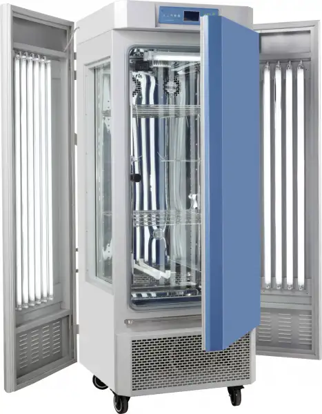
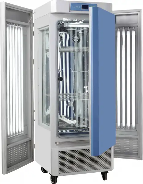
Plant Growth Chamber BCPG-1805
- Microprocessor controller (with timing function)
- • Microprocessor controller for temperature and humidity ensures of precise and reliable control.
- • Simulate changing temperature and light in day/night
- • Independent temperature-limiting alarm system ensures experiments run safely.
- • Polished stainless-steel chamber, semicircular arcs at corners for easy cleaning, and the space between the shelves in the chamber is adjustable.
- • Even air circulation
- • Imported compressor
- • RS485 connector is option which can connect computer to record the parameters and the variations of temperature.(option)
 Get Quote
Specifications
| Model | BCPG-1805 |
| Chamber Volume | 800L |
| Electrical Requirement | 220V 50HZ |
| Power Consumption | 2800W |
| Temperature Range | With Lighting: 10~50°CWithout lighting: 4~50°C |
| Display Resolution | 0.1°C |
| Temperature Stability | ±1°C |
| Temperature Uniformity | ±2°C |
| Ambient Temperature | +5~30°C |
| Humidity Range | 50~90%RH |
| Humidity Accuracy | ±5~7%RH |
| Continuous Working Time | No less than 180h |
| Lighting Intensity | 0~30000LXSix-grade adjustable |
| Lighting Type | Shelves Illumination (two Shelves) |
| Interior Dimension (WxDxH,mm) | 965x580x1430 |
| Exterior Dimension (WxDxH,mm) | 1475x890x1780 |
| Shelves | 3(PCS) |
| Packing Dimension | 156*106*224 |
| CBM | 3.70 |
| Net Weight | 330.00 |
| Gross weight | 480 |
Features
• Microprocessor controller for temperature and humidity ensures of precise and reliable control.
• Simulate changing temperature and light in day/night
• Independent temperature-limiting alarm system ensures experiments run safely.
• Polished stainless-steel chamber, semicircular arcs at corners for easy cleaning, and the space between the shelves in the chamber is adjustable.
• Even air circulation
• Imported compressor
• RS485 connector is option which can connect computer to record the parameters and the variations of temperature.(option)
Options:
• RS485 connector
• CO2 inlet
• CO2 controller (imported IR CO2 sensor)
Applications
Operating Manuals
 Download Manual (PDF)
1. Prompt for safety
2. Schematic diagram
3. Application
4. Structure, Principle and Features
5. Technical Indexes
6. Application
7. Appendix: Operating Instructions for BC1300 Controller
8. Instructions and Maintenance
9. Troubleshooting
1. Prompt for safety
 A prompt for safety assuranceItems enclosed here are extremely important, and must be observed faithfully.
! Dangerous(It might cause serious loss of property or personnel casualty)
1. The product must be earthed reliably and keep far from the interruption of electromagnetism (be sure not taking the zero line and neutral line as earthing line).
2. Before putting into use, confirm that the voltage of power supply is in conformity with the specification of the product.
3. An individual power socket shall be provided for this product, and ensure the earthing for plug and socket is all right.
4. It is not allowed to pull out or plug in the power plug without turning off the power switch during the operation of the product.
5. It is forbidden to extend or cut short the power cable at will.
6. Flammable, explosive, volatile, and corrosive substances must not be placed in the 4/5 groove depth of the refueling upper limit position for drying or baking.
7. It is not allowed to make bold to repair the product. In case of entrusting repair by our company, the work must be done by professional staff.
! Warning(It might cause heavy loss of property or personnel casualty)
1. It can be operated only after the instruction manual is fully read and understand.
2. The stainless steel inner liner is not acid resistant, please pay attention to anti-corrosion measures. Do not use acidic media inside the box!
3. Please do not draw the power cable when pulling out the plug.
4. The power plug of this product must be pull out in case of one the following cases:
4.1 Replacing fuse tube;
4.2 The product goes wrong and standing by for inspection and repairing;
4.3 The product will not be used for long time;
4.4 When moving the product;
5. After the product is turned on, the deviation alarm function must be adjusted or confirmed.
! Notice It might affect the service life and lead to malfunction of the product
1. In case of handling the product, the obliquity should not be large than 45°, so as not to damage the refrigeration system.
2. When the product is transferred to the position, it shall be shelved for one to two days before operation, so as to allow the refrigeration system working in normal condition and extend its service life.
3. The product shall be set on rigid and firm plane to keep it at level status.
4. Enough space shall be remained around the product.
5. The product must be used under a certain condition.
6. Don't open/close the door rudely, or it will result in fall off of the door, damage of the product and injury accident.
7. In case the product is shelved for a long time, the humidity elimination shall be do
2. Schematic diagram

Figure 1

Figure 2
⑴ Touch screen controller | ⑵ RS485 interface (optional) | ⑶ High temp limit setting |
⑷ Light power | ⑸ UV light switch | ⑹ Power Switch |
⑺ Casters | ⑻ Observation window | ⑼ Test hole |
⑽ Overflow | ⑾ Humidifier nozzle | ⑿ Humidifier power outlet |
Table 1
3. Application
BCPG-1805 series Artificial Climate Chamber is a biological culture experimental device that can automatically switch between day and night under a certain temperature, humidity and light intensity to simulate natural light. It can be used for such experiments as plant seed sprouting and seedling, microbe cultivation and feeding of insects and small animals.
4. Structure, Principle and Features
The Artificial Climate Chamber is of a vertical case structure, with the surface sprayed with plastics and the case and door made of cold-rolled sheet by punching. The box adopts a double-layer shelf type lighting structure, and PU foaming material is filled between the outer case and chamber to ensure the thermal insulation. The inner chamber is made of mirror stainless steel sheet; the front side of the artificial climate chamber is equipped with the glass observation window (OBW), through which incubated materials can be clearly observed. The case is provided with cool and hot air ducts inside for the air blower to enhance the smooth air circulation so as to improve the uniformity of temperature and humidity inside the working chamber.
The controller adopts the liquid crystal display, applies the advanced digital circuit technology, and controls the various parameters of the climate box (including the number of blocks, temperature, illumination and time) through the programmable control method of the CPU processor.
The Artificial Climate Chamber has the following features and protective functions:
1. After a power failure, it has a memory function for the parameters that were running before the power failure.
2. With ultraviolet disinfection and sterilization function.
3. In order to protect the compressor, there is a 3-minute delay start protection function in the system; at the same time, the refrigeration system of this equipment adopts dual compressor configuration conversion work, which can provide users with longer continuous operation.
4. Over-temperature limit temperature protection: When the actual temperature of the light box exceeds the set limit temperature, the power supply of the heating and light parts in the box will be automatically interrupted, and an audible and visual alarm will be issued. When the temperature naturally drops below the limit temperature, the inside of the box resumes heating, and the cycle repeats. When such a phenomenon occurs, it indicates that the light box is faulty, and the cause of the fault should be found out, and normal operation can be restored after troubleshooting.
5. Optional RS485/232 interface and communication software.
5. Technical Indexes
Index Model | BCPG-1805 |
Temperature range | without lighting:4~50°C with lighting:10~50°C |
Temperature resolution | 0.1°C |
Temperature fluctuation | ±1.0°C |
Humidity control range | 50~90%RH |
Humidity deviation | ±5~7%RH |
Lighting intensity | 0-30000LX Six grade adjustable |
Lighting method | Clapboard type lighting (two layers) |
Input power (W) | 2800W |
Working temperature | +5~30°C |
Studio size W*D*H(mm) | 965x580x1430 |
Outer size W*D*H(mm) | 1475x890x1780 |
Table 2
Note 1:Six grades of adjustable lighting: 10%, 20%, 50%, 70&, 90%, and 100%
6. Application
1. Ambient conditions for normal operation of the Plant Growth Incubator:
a) Ambient temperature: 5°C~35°C.
b) Relative humidity: ≤85%.
c) Air pressure: (86~106) KPa
d) Altitude: <2,000m.
e) Power supply: AC(220±22)V (50±1)Hz
f) Without corrosive gas around and away from electromagnetic interference.
g) The chamber should be grounded.
2. Switch on and set such parameters as for required temperature and illumination intensity as per operating method of the instrument.
3. Add accessories humidifier with distilled or purified water, and plug the power plugs of the three humidifiers into the humidifier's power outlet on the side of the climate chamber. The nozzles of the humidifier is connected to the white air intake located in the middle of the back of the cabinet.
4. With the Artificial Climate Chamber running for every 15 days, in case of any static error (e.g.: it
is set as 20 °C , but it is actually more than 22 °C ), it is necessary to "Defrost" for the Artificial Climate Chamber: set the temperature as 40°C, keep the Artificial Climate Chamber running for more than 3 hours and then reset the required parameter for running.
5. If the chamber needs to be disinfected and sterilized, turn on the "UV light switch" for UV disinfection.
6. Application of "Overheating Protector"
Overheating Protector is an independent protection system. When the temperature is out of control due to the fault of the temperature controller and the temperature inside the working chamber is up the pre-set value of temperature limit on the overheating driver panel, the overheating protector will automatically cut off heating and alarm.
(As shown in Figure) when the temperature inside °C the working chamber is lower the set value, the protection system is canceled and the instrument
returns to running. It is repeated till the fault is eliminated. Particular operating is as follows:

Figure 3
6.1 The set value of temperature limit should be ≥ (SV) + (5~10) °C
6.2 Use +/- button the overheating setting
driver panel to set the required temperature limit
For example: SV=37°C
The set value of temperature limit should be set as (42~47)°C.

Figure 4
7. Appendix: Operating Instructions for BC1300 Controller
1.Startup Main Screen

Figure 5
(Screen 1)
No. | Descriptions |
(1) | Displays the current date/time. |
(2) | Displays the present temperature value (PV) |
(3) | Displays the present humidity value (PV) |
(4) | Button to move the operation screen |
① | Click for Run Stop screen. |
② | Click for Function and Value Setting screen. |
③ | Click for Present Time and Appointed Startup Time screen |
④ | Click for Program Curve View screen |
⑤ | Click for Program Setting screen. |
⑥ | Click for Display Setting Screen. |
Table 3
Click  in the fix operation run or stop screen.

Figure 6
(Screen 2)
No. | Descriptions |
① | Click for Main Screen (Screen 1) |
② | Display the present actual temperature |
③ | Set temperature target value |
④ | Display present time |
⑤ | Set humidity target value |
⑥ | Display present actual humidity |
⑦ | In STOP state, click for Set RUN STOP screen(Screen 3) |
⑦ | In RUN state, click for Set RUN screen (Screen 4) |
⑧ | Run/Stop shift |
Table 3
3.Click  in
in

Figure 7
(Screen 3)
No. | Descriptions |
① | Select program mode and fixed-value mode |
② | Select STOP, Cold Startup and Warm Startup after power-off |
③ | Select Action or Non-action |
④ | Gradient for temperature/humidity rising/dropping per minute |
⑤ | Enable or Disable; with Enable selected, set time up to RUN/STOP |
⑥ | Select Enable or Disable, with password |
⑦ | When the key is locked, the font is red, while other keys cannot be operated |
Table 4
★Note:
1. Only the temperature and time can be set in the setting mode, but the lighting cannot be set.
2. In program mode, temperature, time, and illumination can be set separately; this machine is recommended to use program mode;
4. Click  in
in

Figure 8
No. | Descriptions |
① | Setting of present time |
② | Setting of to starting time for controller |
③ | When Preset key in red fonts, it indicates the success of Start-up Presetting |
Table 5
5.Click  in
in

Figure 9
(Screen 8)
No. | Descriptions |
① | View the curve of program with different numbers |
② | When viewing the program curve, select different time |
③ | Red curve indicates temperature and blue curve indicates humidity |
Table 6
On Screen 8, click the switch in the upper right corner to enter Screen 9.

Figure 10
(Screen 9)
No. | Descriptions |
① | When viewing curves, the time can be zoomed out or in |
② | Click PV File to view the previous curves |
③ | When viewing curves, shift the cursor to view the temperature/humidity value of different time quantum |
Table 7
On Screen 9, click the switch in the upper right corner to enter Screen 10.

Figure 11
(Screen 10)
No. | Descriptions |
① | Time interval for recording PV curves, from 1s to 1min |
② | Automatic or manual |
③ | Set the upper and lower limits of PV temperature curves |
④ | Set the upper and lower limits of PV humidity curve |
Table 8
On Screen 10, click the switch in the upper right corner to enter

Figure 12
(Screen 11)
No. | Descriptions |
① | Download or upload the necessary backup items |
② | Upon completion of item backup, press SEND key, which shall be operated in STOP state |
Table 9
6. Click  in
in

Figure 13
(Screen 12)
6.1 Click  in
in
 BCPG-1805")
Figure 14 (Screen 13)
No. | Descriptions |
① | Set program groups of 1~120 |
② | Conditional actual value, temperature SSP or humidity SSP for the program group to start running |
③ | Display temperature value of edited program group |
④ | Display humidity value of edited program group |
⑤ | Display the time of edited program group segments |
⑥ | Display the time signal of edited program group segments |
⑦ | Fan speed for segments of program group can be selected as High, Medium and Low |
⑧ | For editing the program, first click "Segment" and then click "Insert/Delete" key |
⑨ | For editing the program, click the key for turning pages forward and backward |
Table 10
★Note: The setting of light is in the time signal, see the table below
Sattus Six grade adjustable | Ts1 | Ts2 | Ts3 | Ts4 | Instructions |
0% | 01 | 00 | 00 | 00 | No light |
20% | 00 | 01 | 00 | 00 | / |
40% | 00 | 00 | 01 | 00 | / |
60% | 01 | 01 | 00 | 00 | / |
80% | 00 | 01 | 01 | 00 | / |
100% | 01 | 01 | 01 | 00 | Full light |
Table 11
Note: Click on the upper right corner of the screen to return
6.2 Click  in
in

Figure 15
(Screen 14)
No. | Descriptions |
① | Select program group |
② | Frequency of program group circulation, connectable with other program groups |
③ | Circulations of program group segments |
④ | Circulating mode of program group segments, optional for final SP or initial SP |
⑤ | Termination of whole program group, optional for STOP, SUSPEND or LINK RUN |
Table 12
6.3. Click  in
in

Figure 16
(Screen 15)
No. | Descriptions |
① | Input the existing program groups |
② | Input the number of program group to be copied, from starting to ending group, then click Copy key |
③ | All the edited program group file information will be then displayed |
④ | Input the number of program group to be deleted and then click Delete Selectively or Delete All |
Table 13
6.4. Click  in
in

Figure 17
(Screen 16)
No. | Descriptions |
① | Wait for setting Enable or Disable |
② | When temperature/humidity enters the range of waiting, the program will start timing |
③ | Waiting time starts only after temperature/humidity enters the range of waiting, |
④ | Optional for program group or segment waiting |
Table 14
7. Click  in
in

Figure 18
(Screen 17)
No. | Descriptions |
① | Automatic or manual |
② | Optional for the prime color of controller |
③ | utton controlling the buzzer switch |
④ | Backlight time can be set for 0~99min |
⑤ | Adjust the controller brightness |
⑥ | Display the internal storage of controller |
Table 15
Click the toggle key for checking the record of previous faults

Figure 19
(Screen 18)
8. Instructions and Maintenance
1. In handling the Artificial Climate Chamber, it is prohibited to place it upside down or at an incline of more than 45 degrees.
2. With the Artificial Climate Chamber positioned, it should be leveled up if the ground is uneven.
3. With the Artificial Climate Chamber running normally, the materials inside should not be excessively packed and should affect the air circulation inside to ensure the even temperature inside.
4. When illumination is not required inside, the illumination switch should be in the position of "OFF" to avoid affect the upper temperature as well as prolong the useful life of the lighting tube.
5. The inner chamber and the case surface should be frequently wiped to keep them clean and increase the transparency of the glass. Do not clean the outer surface with acid, alkali or other corrosive solutions.
6. If the Artificial Climate Chamber is kept idle for long, it is necessary to pull out the power cable and regularly (generally once every quarter) run it for 2~3 days as per application conditions so as to eliminate moisture on the electric parts and avoid any damage to the relevant parts.
7. Upon being stopped for standing idle, the Artificial Climate Chamber should be dehumidified in the following method: clean the case inside before setting the temperature at 40 °C, run it for 5 hours, and dehumidify every two hours by opening the door. Afterwards, pull out the power cable and keep the unit in a proper place.
Note: Lighting time error ≤ 5 ‰!!
9. Troubleshooting
Faults | Possible causes | Action |
Without power upon switching on (Indicator not lit) | Power socket is inactive or in poor | Repair |
Power cable is broken or not properly | Repair, re-plug-in | |
Power switch is damaged (or not on) | Replace, turn on the power switch | |
Fuse burnt out | Insert the appropriate fuse tube, if it breaks again, check the cause and rectify it after troubleshooting | |
Loss of control of temperature and humidity | Instrument damaged, sensor broken | replace |
Compressor damaged | replace | |
Fan damaged | replace | |
No "defrost" treatment | Set 40°C, run for more than 3 hours | |
Freon leak or capillary blockage | Add refrigerant R22, discharge plug | |
Illumination out of control | Most of the feet are not squared | Rotate the lamp foot well |
Electronic ballast damage, bad lamp | Replace after inspection | |
Control instrument failure | Replace after inspection | |
The water in the box cannot be discharged | The water in the box cannot be discharged | dredge |
Fan sound abnormally or has a big noise (>70dB(A)) | Studio lower plastic bracket fixing screws loose | Secure |
Air deflector is not embedded in the slot | Reload | |
Loose plate screws for hot and cold rooms, loose screws for heater tubes | Secure | |
The fan is entangled by a foreign object | Clear | |
Uneven box | Four-wheel wheel flat | |
Check compressor and cooling fan |
Table 16
Packing List
Sr. No. | Type | Description | Unit | Qty | Remarks |
1 | Document | User's Book | Copy | 1 | |
2 | Document | Packing List | Copy | 1 | |
3 | Accessory | Humidifier | Pc | 1 | |
4 | Accessory | Shelf | Pc | 3 | |
5 | Spare part | UV Lamp | Pc | 1 | 8W |
6 | Accessory | Water pan | Pc | 1 |
Table 17