Get Price
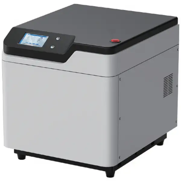
Microwave Digester BMWD-101
- • Compatible with 6/8/10-position sample rotor.
- • Germany contactless IR sensor and pressure sensor, real-time display the temperature and pressure of sample solution
- (NOT Vessel Wall) in each vessel and show T&P scanning curve.
- • No consumables, e.g. bursting disk, sealing cup, etc. lower maintenance cost.
- • Equip with a smart 7 inch touch screen, user-friendly UI.
- • Pre-installed multiple international application methods. Users can also edit, modify and delete the methods.
- • Equipped with 316L stainless explosion-proof cavity, coated with multi-layer anti-corrosive and heat resisting coatings, which greatly prolongs its service life and ensure the safety of operation.
- • High power turbulent air cooling design makes fast cooling.
 Get Quote
Specifications
| Model | BMWD-101 |
| Vessel Quantity | 6 |
| Pressure Monitoring | Contactless pressure sensor |
| Max. Working Pressure Range | 6MPa |
| Temperature Monitoring | Contactless IR sensor |
| Max. Working Temperature | 250°C |
| Temperature Accuracy | ±0.1°C |
| Vessel Volume | 100mL |
| Display | 7 inches Color Touch Screen |
| Rotation | 360° continuous rotation |
| Microwave Power | 0-1000W (Adjustable) |
| Microwave Frequency | 2450MHz |
| Cavity Volume | 35L |
| Microwave Leakage | <5mW/cm2 |
| Power | AC 220V±10%, 10A, 50/60Hz |
Features
• Germany contactless IR sensor and pressure sensor, real-time display the temperature and pressure of sample solution
(NOT Vessel Wall) in each vessel and show T&P scanning curve.
• No consumables, e.g. bursting disk, sealing cup, etc. lower maintenance cost.
• Equip with a smart 7 inch touch screen, user-friendly UI.
• Pre-installed multiple international application methods. Users can also edit, modify and delete the methods.
• Equipped with 316L stainless explosion-proof cavity, coated with multi-layer anti-corrosive and heat resisting coatings, which greatly prolongs its service life and ensure the safety of operation.
• High power turbulent air cooling design makes fast cooling.
• Professional electromagnetic protection design, compatible with high-level microwave leakage protection standards.
Operating Manuals
 Download Manual (PDF)
Packing list
1. Important notes
2. Instrument Structures and Accessories
2.1 Main body
2.2 Digested vessel
2.3 Rotor
2.4 Other accessories and tools
3. Flow of Instrument Installation
4. Technical parameters of the instrument
5. Safety Guide
5.1 Operation safety guide
5.2 Digestion vessel safety guide
5.3 Pressure & temperature module safety guide
5.4 Sample & reagent safety guide
5.5 Other important notes
6 Operation Guide
6.2 Introduction of the operation interfaces
7. Discussion on Microwave Digestion and Methods
7.1 Discussion on microwave digestion
7.2 Microwave digestion methods
8. Questions and Answers (FAQ)
Packing list
Instrument Name:Closed Intelligent Microwave Digestion/Extraction Instrument
Instrument model:BMWD-101
No. | Item Name | Pictures | Quanity | Unit | |
1 | Instrument | Main body | | 1 | set |
2 | Accessories | Digestion Vessels (Inner vessels+ Outer vessels) | | 6 | set |
3 | Sample loading platform | | 1 | set | |
4 | Auxiliary platform | | 1 | set | |
5 | Elastomer (spare) | | 30 | pcs | |
6 | Inner vessel shelf | | 1 | set | |
7 | Repair tool | | 1 | pcs | |
8 | Upload tool | | 1 | pcs | |
9 | Signal board | | 2 | set | |
10 | Exhaust pipe (Including hoop) | | 1 | pcs | |
11 | Measured tool of elastomer | | 1 | set | |
12 | Fuse 10A | | 2 | pcs | |
13 | Sandpaper | | 1 | pcs | |
14 | Power Cord | | 2 | pcs | |
15 | Operation manual (Include warranty) | | 1 | pcs | |
16 | Disposable gloves | | 1 | pair | |
17 | Cross screwdriver | | 1 | pcs | |


1. Important notes
1. This equipment matches one grounding plug. This grounding plug must insert into a reliably grounded socket.
2. Do not open the shell of the instrument without the permission of the manufacturer to prevent microwave leakage or safety accidents.
3. It is forbidden to digest hazardous substances such as organic solvents, explosives, strong oxidants and long strip or block metal samples at will; Do not digest phenol, triethylamine and animal fat with nitric acid; Samples containing fat, oil, ethanol, nitroglycerin, aromatic compounds and nitroaromatic compounds must be properly pretreated before closed microwave digestion, otherwise it will cause vessel explosion. Please refer to《the table of samples that cannot be digested or cannot be digested directly by closed microwave digestion instrument (a part) 》.
4. Nonpolar substances do not absorb microwave, which will cause no temperature rise or difficulty in temperature rise, thus damaging digestion vessels, instrument accessories or instruments; Only polar substances can absorb microwaves. Please make sure that the reaction reagent contains polar substances, otherwise it will cause magnetron to ignite, burning out the instrument and causing safety accidents. For the electrolytic constants of polar substances, please refer to 《the polarity table of some common organic solvents》.
5. Reference value of sample quantity:
• Common sample: drying powder sample ≤500mg,liquid sample ≤10Ml. Please reduce appropriately sample quantity according to the difficulty of sample digestion and sample viscosity;
• The unknown sample:50mg-100mg;
• Organic sample:100mg;
• Inorganic sample:≤500mg.
6. The dosage of reagent HNO3, HCl and HF below 200 °C is not strictly limited; H2O2 can be added appropriately to promote the digestion effect; High boiling acids such as H2SO4, H3PO4 and F4B2 cannot be used alone, and it is recommended to use them together with other acids; HClO4 is strictly prohibited.
7. During digestion of each batch of samples, it must be ensured that the type of samples is consistent, and the sample weight, reagent type and reagent quantity of samples are consistent.
8. It is strictly prohibited to operate in violation of the operating procedures or digest sample in excess of the maximum operating temperature or pressure.
9. The instrument is only for professional use, not for ordinary heating.
10. When the operator changes, be sure to contact the after-sales department of our company in time. The company will not be responsible for any problem if the personnel have not been trained by the company or the operator does not operate according to the specified requirements.
2. Instrument Structures and Accessories
2.1 Main body
2.1.1 Introduction to main body

Figure 1
Exterior Structure

Figure 2
Inner Structure
2.1.2 Main body parameter
Working power supply: AC 220V (±10%); 50 Hz /60Hz; 10A;Good grounding.
Rated microwave output power: 0~1000W
Microwave frequency: 2450MHz
Boundary dimensions (length x depth x height): 490mmx560mmx520mm
Suttle: 41Kg
2.1.3 Operating environmental requirements
Environment temperature:5~40°C
Environment humidity:45~70%RH
Good ventilation, no outer corrosive gas, no outer strong magnetic interference, and avoiding direct sunlight
2.2 Digested vessel
2.2.1 Digestion vessel parameter
Digestion vessel is made up of inner vessel and outer vessel; Maximum operating temperature is 250°C; Maximum operating pressure is 6MPa;
Inner vessel material: imported TFM;
Outer vessel material: composite material (imported PEEK mixed glass fiber)
2.2.2 Digestion vessel

Figure 3
2.2.3 Outer vessel accessories and pressure module

Figure 4
Main Control Vessel

Figure 5
Pressure Module
2.2.4 Assembly of digestion vessel
(1) Assembly of outer vessel cover assembly
A. Insert the elastomer into the guiding rod;
B. Make the convex part of the cushion block upward, then insert the cushion block into the guiding rod;
C. Put the guiding rod into the outer vessel cover;
D. Lock guiding rod and outer cover with lock nut;
E. ※ Screw the signal board into guiding rod, and tighten slightly. It's better to rotate the signal board until it meets resistance, and then tighten it a little more (Note: when assembling the outer vessel cover assembly of the main control vessel, it should screw the assembled ABCD assembly into the outer vessel and insert the temperature sensor before operating step E).
F. Assembly completes.

Figure 6
(2) Assembly and sample loading process of digestion vessel
 Assembly and sample loading process of digestion vessel")
Figure 7
2.2.5 Open process of the digestion vessel
(1) Open process of the digestion vessel
 Open process of the digestion vessel")
Figure 8
(2) Gesture diagram of digestion vessel opening process

Figure 9
2.2.6 Notes
(1) Note: The elastomer in the pressure module is an important component in pressure control system. During use, it is necessary to regularly check the property changes of the elastomer for timely replacement.
• After each digestion, please wash the elastomer with warm water in time, and then dry in the shade. It cannot be exposed to sunlight, blown by wind or dried in oven., the elastomer with warm water in time, and then dry it naturally in the shade. It cannot be dried in the sun, wind or oven.
• If the elastomer becomes yellow, hard, cracked or thin (when the thickness of the elastomer can freely pass through the gap in the elastomer measuring tool), please replace it in time to avoid affecting the accuracy of pressure detection and vessel explosion.
• The elastomer shall be assembled in an outer vessel or sealed in a zip block bag for storage, and shall not be directly exposed to the air.
(2) When blank and sample are digested in the same batch, the main control vessel must be the sample vessel instead of the blank vessel, and the main control vessel should be the digestion vessel with the largest sample weight.
(3) Inner vessel sealing inspection: When slowly pressing the sealed cap into the cup body there is a friction; when quick pull out the sealed cap from the cup body there should be a sealed sound. Before using the sample digestion vessel, please match the cup body and the sealed cap first, so as to ensure the good sealing performance of the combined sample digestion vessel.
(4) When the cup body is covered with a sealed cap, pay attention to the gestures and methods of holding the vessel. The index finger presses the sealed cap, and the other four fingers grasp the inner vessel body or the outer vessel body.

Figure 10
(5) Slightly tighten: when assembling relevant parts, tighten them again after encountering resistance when rotating or pulling, so that the parts will not loosen without outer force.
(6) When opening the digestion vessel, if there is still air pressure in the vessel, be sure to slowly relieve the pressure several times before opening the outer vessel.
(7) When cleaning the sealed cap of the main control vessel, take out the temperature sensor.
(8) The same digestion vessel cannot be used for both microwave digestion and microwave extraction. Digestion and extraction should be dedicated to ensure the safe use of the instrument.
(9) As polar solution cannot be used for microwave digestion or extraction, it is necessary to ensure that the solution in the digestion vessel can absorb microwave during digestion or extraction.
2.3 Rotor
2.3.1 Composition of rotor
The rotor is composed of temperature connector, driver, auxiliary platform and sample loading platform.
2.3.2 Drive shaft(axle)
")
Figure 11
Drive shaft
2.3.3 Platform structure


Figure 12
Auxiliary platform

Figure 13
Sample loading platform (T6)
2.3.4 Rotor and digestion vessel
(1) Picture of full canister carries
 Picture of full canister carries")
Figure 14
Picture of full vessel loading(T6)
(2) Diagrammatic picture of digestion vessel loading (T6)

Figure 15
Loading diagram of digestion vessel
(3) Note
1) In order to improve the consistency of heating effect, please load the digestion vessel according to the above scheme;
2) When the full vessel is loaded, a blank vessel shall be loaded next to the main control vessel, except for no blank vessel;
2.3.5 Type of sample loading platform
BMWD-101 series sample loading platform is divided into three types: A, B and C; The number of digestion vessels loaded is 6, 8 and 10 respectively.
2.4 Other accessories and tools
(1) Inner vessel shelf: Tube transfer shelf of inner vessel cup body which uses to transfer, take and put cup body.
(2) Exhaust duct: Connect the main engine and the laboratory exhaust system to discharge waste gas in a centralized manner.
(3) Repair tool: Repair the sealed cap with poor sealing performance. Usage: press the round head end of the repair tool into the sealed cap, press it concentrically, rotate the repair tool for 1 ~ 2 minutes, and then pull it out.
(4) Upload tool: After digestion, the outer vessel and the inner vessel are sometimes adsorbed together, which is difficult to separate, especially when there is acid leakage. In this case, please use the can removal tool to push the inner vessel through the round hole at the bottom of the outer vessel, and pull the outer vessel down with force to separate the inner vessel from the outer vessel.
(5) Signal calibration board: Calibrate the inner pressure signal value of the instrument. Each set of signal calibration board consists of one pcr-5 (thick ring board) and one pcr-2.5 (thin ring board). Users can calibrate the instrument [instrument calibration interface] under the guidance of our engineers or after referring to the instrument calibration tutorial provided in the instrument touch screen control display.
(6) Elastomer measuring tool: When the thickness of the elastomer can freely pass through the gap in the tool, it means that the elastomer is no longer available and needs to be replaced.
(7) Sandpaper: adjust the parameters of signal board.
(8) Fuse: spare parts.
3. Flow of Instrument Installation
3.1 Open the box for inspection
Please do not put the packing boxes horizontally, upside down or stacked at will. Please do not strike the packing case violently when unpacking. Open the packaging box of the instrument host, carefully and remove the host and place it on the prepared workbench. Check whether there are obvious defects in the appearance of the instrument, and check whether the furnace door switch function is normal. Note: After unpacking, please do not discard the packing case immediately, and deal with the equipment after 1 ~ 2 weeks of stable use, in case the equipment needs to be replaced due to unstable signal caused by turbulence in transportation.
3.2 Check goods
After unpacking, please check the instruments and accessories according to the attached list. If any problem is found, please contact our agent or our company.
3.3 Installation

Figure 16
(1) Take out the exhaust pipe, cover the end of the exhaust pipe installed with a hoop into the exhaust vent of the instrument, and lock the hoop tightly; Plug the other end of the exhaust pipe into the exhaust system.
(2) Remove the auxiliary platform, turn the beads upwards and snap them onto the two positioning pins in the furnace chamber.
(3) Remove the loading platform. Place its vessel positioning ring facing upwards, and attach it to the drive hinge. Make sure that the direction of the thickness end of the drive hinge card slot should be consistent with the direction of the thickness end of the drive hinge.
(4) The assembled digestion vessel is loaded on the vessel positioning ring of the loading platform. If it is multi-vessel loading digestion, arrange the digestion vessels evenly on the vessel positioning ring. Note: The temperature sensor of the main control vessel must be inserted into the temperature connector.
(5) Plug power cord into instrument and socket.
Note: The power voltage used by instrument is 220V, which it is possible to cause electrocution injury or death. Before connecting the power cord, please confirm that the power switch is off "0"; the work of connecting the power cord to the instrument must be done last.
(6) After confirming that the connection between the power cord and the ground wire is normal, turn on the instrument's power switch and the instrument automatically performs an initialization check. When the initialization is completed, the instrument automatically jumps into the system detection interface, at this time, if the furnace chamber is not loaded with digestion vessels, the prompt text box of the system self-test interface will display "Digestion vessel not detected", the user can load 1 to multiple digestion vessels according to the actual situation. Then close the furnace door, click the [Detection] button to continue the unfinished detection, and then enter the [Login Interface]. If you need the administrator permission function, enter the password in the password box of the [Login Screen] and click [Login] to enter the [Function Selection Interface]; if you only perform the general operation function, click the [Skip] button directly in the [Login Screen] to enter the [Program Method Interface].
4. Technical parameters of the instrument
Instrument model | BMWD-101 | ||
Number of digestion vessels | 6sets | 8sets | 10sets |
Platform model | TP-6 | TP-8 | TP-10 |
Microwave power | 0 ~1000 W(Arbitrary adjustable) | ||
Microwave frequency | 2450MHz | ||
Working pressure range | 0~6MPa | ||
Pressure control mode | All vessel controlled | ||
Pressure monitoring method | Non-contact fiber scanning load measurement | ||
Temperature control mode | The main control vessel controls the temperature | ||
Temperature monitoring method | Precision platinum resistance temperature measurement | ||
Maximum operating temperature | 250°C | ||
Temperature control accuracy | ±0.1°C | ||
Temperature control range | -50 ~400°C | ||
Inner vessel volume | 100ml or 60mL | ||
Digestion vessel type | DV-S100E | ||
Display | 7inch large touch screen | ||
Turntable rotation way | 360°continuous rotation | ||
Furnace chamber volume | 36L | ||
Microwave leakage | Under 5mw/cm2 | ||
Power | AC220V10%,10A,50/60Hz | ||
Outer dimensions(LxWxH) | 490mmx560mmx533mm | ||
Host net weight | 41kg | ||
Table 1
5. Safety Guide
Read the following safety guide carefully before operation. Please keep the safety guide in a convenient place for future reference.
5.1 Operation safety guide
5.1.1 CAUTION: Do not do empty run. There must be one or more digestion vessels on the rotor which are filled with the sample solution or acid.
5.1.2 Keep instrument clean.
5.1.3 The instrument is with high voltage and microwave ray. All the users or relevant personnel should be trained and certified to avoid any problem caused by high voltage or microwave ray.
5.1.4 It is not allowed to install the instrument in the fume hood to avoid any damage or problem caused by acid or chemical gas.
5.1.5 Please exchange the air when use sample or reagent that is harmful to human being or environment. If there is no enough air exchange, it might affect normal performance of the instrument or users' safety.
5.1.6 To avoid any danger, please do not disassemble instrument or change spare parts, and do not replace the parts or take off the safety devices.
5.1.7 Make sure there is enough space for convenience of user's operation.
5.1.8 Warning: The 220V voltage may cause electrical shock hazards, please make sure all the power is off before connecting the power cord to avoid any injury cause by high voltage.
5.1.9 WARNING: Make sure all the power is off and all the power cord is disconnected before maintenance.
5.1.10 WARNING: The magnetron and high voltage electric parts inside will cause high temperature which may result in injury. Make sure all the power is off and the power cords are disconnected and wait for the instrument cooling down before replacing any parts to avoid any injury.
5.2 Digestion vessel safety guide

Figure 17
5.2.1 NOTE: During the assembly or disassembly the digestion vessel, please be sure to wear acid proof gloves.
5.2.2 CAUTION: Make sure all parts of the digestion vessel, inner vessel (sample digestion vessel) or outer vessel (outer protective vessel) are dry and clean. The sample rotor, auxiliary platform and inner surface of furnace chamber should also be clean and dry.
5.2.3 Pay attention to the tightness when tightening the outer vessel, it's better to rotate the vessel cover until it meets resistance, and then tighten it for about 15 °.
5.2.4 CAUTION: Please wear acid proof and heat insulation gloves to take the vessels out due to high temperature after digestion to avoid getting burnt.
5.2.5 When cleaning the inner vessel, use tap water to wash and put in 25% of the dilute nitric acid (HNO3) for more than 12 hours, and then clean it three times with distilled water or deionized water and then dry. If the inner wall is too dirty, please use soft sponge rubbing to clean inner wall first. It is not allowed to wash with tube brush. Or add 10ml concentrated nitric
acid and clean it in the instrument, the program method is: Pressure 25 Bar, Temperature 180°C, Power 1000W, Heat-Time 200s and Hold-Time 600s.
5.3 Pressure & temperature module safety guide

Figure 18
5.3.1 The pressure components are an important part and is the key to pressure protection, whose elastomer is an important component. After digesting the sample each time, please clean the elastomer in time and check the state change of the elastomer.
regularly. If the elastomer turns yellow, hard, cracked or can easily pass through the elastomer measuring tool, please replace it in time to avoid affecting the accuracy of pressure detection and vessel explosion. Note: Please assemble the pressure module according to the correct method and sequence, and clean and maintain the pressure module in time.
5.3.2 The signal board is a high precision part of the pressure module. Please make sure the signal monitoring surface is flat and smooth and there is no scratch on it. It is not allowed to do any marking on this surface.
5.3.3 Please use alcohol cotton swab to clean the pressure probe and the temperature probe after each experiment.
5.3.4 Please use wet cotton swab to clean the temperature sensor and temperature connector.
5.3.5 If temperature module has deviation, please contact us for temperature calibration.
5.4 Sample & reagent safety guide
5.4.1 General sample weigh:If the sample is solid, it should less than 0.5g; if liquid, it should be less than 10ml. NOTE: Please reduce the sample volume appropriately according to the difficulty of the sample digestion and the viscosity of the sample. The total volume in the inner vessel is between 8ml and 35ml, not less than 7 ml and not more than 50ml. Each inner vessel shall be the same sample, the same acid, and with the same quantities.
5.4.2 For unknown samples and samples with high organics, the best sample volume is 0.1g. Also, it needs pre-digestion for 15-30 minutes at least (Please choose SPH-1 Sample Pretreatment Heating Equipment). The digestion vessel could not be sealed or closed during the pre-digestion.
5.4.3 The samples containing fat, sugar, oil, nitroglycerine, aromatic compounds, nitro aromatic compounds, organic solvent or volatile samples must do pre-digestion before the microwave digestion.
5.4.4 It is forbidden to directly digest the sample containing ethanol. The sample should be dried by the water bath and then do microwave digestion.
5.4.5 There is no limitation for HNO3, HCl, HF under 200°C. H2O2 can be added properly to improve the efficiency of digestion, but it should do pre-digestion. High boiling acid, such as H2SO4, H3PO4 and F4B2, can't be used alone, and the amount of use above 200 degrees centigrade should be restricted according to the actual conditions. HClO4 is strictly prohibited to use. The acid reagent in each inner vessel should be the same volume and type.
5.4.6 When the sample of the same batch is digested, it is necessary to ensure that the digestion is under the same amount of the same acid in the same quantity of the same sample.
5.4.7 When digesting or extraction, it is necessary to ensure that the solution in the digestion vessel can absorb microwaves, and non-polar solutions cannot be used.
5.4.8 Please don't place the corrosive reagent such as sample reagents, acid and alkali reagent near the instrument. Also be careful when taking samples to avoid spilling out to the instrument surface or the chamber. If spilled out, please use soft cloth or paper to clean.
5.4.9 WARNNING: The following samples cannot be digested. It does not mean that it is absolutely safe to digest samples digest samples which are not listed here.
(1) Explosive samples (TNT, Cellulose nitrate etc.);
(2) Propellant (hydrazine, hydrazinium, ammonium perchlorate etc.);
(3) Flammable samples; Nitroglycerin, nitroglycerin or other organic nitro compound;
(4) Two samples that mixed together can be flammable (nitric acid & phenol, nitric acid & triethylamine, nitric acid & acetone;
(5) Aircraft fuel (JP-1 etc.);
(6) Acetylene compound;
(7) Diol (e.g., ethylene glycol, propylene glycol, ethylene glycol, propylene glycol);
(8) Perchlorate (Ammonium perchlorate,Potassium perchlorate etc.);
(9) ether compounds;
(10) Paint samples;
(11) Alkanes;
(12) Ketones;
(13) Pure fat in animals.
5.5 Other important notes
5.5.1 About the Operation Manual
(1) This operation manual content might be changed without prior notice.
(2) This operation manual copyright belongs to the technology department of our company.
5.5.2 Please comply with all the important notes in the operation manual. If not, it might cause injury or damage on instrument.
5.5.3 Please don't do other operations that did not list on the operation manual. If there is any problem, please contact the distributor or our company.
5.5.4 Although all situations have been taken into account in the manual, but unexpected situation might happen. Please strictly follow the operation manual instructions and also be careful during operation to avoid any accident.
6 Operation Guide

Figure 19
6.2 Introduction of the operation interfaces
6.2.1 Instrument initialization and automatic system diagnosis interface

Figure 20
(1) Before turning on the power, please check all wires to ensure all wires have been connected properly.
(2) Check the chamber, and make sure the auxiliary platform and the sample rotor are normally, then close the door.
(3) Turn on the power, the instrument starts to initialize.
(4) When initialization finished, system will go into the Automatic System Diagnosis Interface.
6.2.2 Automatic system diagnosis interface

Figure 21
(1) When first use the instrument or doing periodic diagnosis, please load one assembled digestion vessel according to the requirements and click the button of [CHECK] to continue system diagnosis.
(2) The problems found during the Automatic System Diagnosis will be prompted to display in the long text frame of the interface. Click [SKIP] button to enter the Login Interface. In the Login Interface, click [Help] button to enter the Help Interface and user can refer to related questions and analysis (FAQ).
(3) After System Diagnosis, system will enter directly Login Interface.
6.2.3 Login interface

Figure 22
![Figure 23, (1) Click the password display frame, enter the login password (Initial password: 1234), click [√] to confirm.](https://biolabscientific.com/content/manual/20260603001/Figure-23-i42-Biolab.webp "Figure 23")
Figure 23
(1) Click the password display frame, enter the login password (Initial password: 1234), click [√] to confirm. Then click [login] button to enter the Function Selection Interface (administrator).
(2) Click [Reset Password] button and enter Reset Password Interface. The administrator can modify the login password (four digits) on this interface.
(3) Click [Help] button to enter the Help Interface and users can refer to related questions and analysis (FAQ).
(4) Click [Skip] button to enter the Program Method Interface (non-administrator).
6.2.4 Program method interface(non-administrator)
")
Figure 24
(1) Enter the Program Method Interface, the system will load digestion system that used last time by default.
(2) The system can set 1-255 kinds of program methods. There are 8 preset program methods in the Program Method Interface, which help users to enter the digestion process conveniently and quickly.
(3) Click the name of left program method can load the corresponding program. If user needs to load 9-255 program methods, please input the corresponding number into the text box of the program No. and click the [Load] button.
(4) Under normal permissions, user cannot modify the related parameters in the program or create a new digestion program. Please enter the administrator's Program Method Interface, and then create or edit the method program.
(5) Click [Esc] button to enter the [Login Interface].
(6) Click [Apply] button to enter the [Run Interface].
6.2.5 Run interface

Figure 25
6.2.5.1. Working parameters are displayed in real time on the right side of the run interface.
(1) It means the door closed safely when the door status light is green. User can click [START] to start the application program for sample digestion. It means the door closed unsafely when the door status light is grey, and then the button of [START] is invalid. Please check whether the door is closed safely or not.
(2) When microwave status light is green, it means the instrument in working status. Do not lean on the instrument to avoid microwave irradiation.
(3) T value display frame: Display in real time the highest temperature value (TH), the lowest temperature value (TL) of the reagent in all digestion vessels and the program setting pressure value (Tset).
(4) P display frame: Display in real time the highest pressure value (PH), the lowest pressure value (PL) of the reagent in all digestion vessels and the program setting pressure value (Pset)
6.2.5.2. On the left side of the run interface
(1) Diagram of curves: The red frame is the temperature curve frame, which shows the change of the temperature in the digestion vessel in real time. The blue frame is the pressure curve frame, which shows the change of the pressure in the digestion vessel in real time. The digestion time between the red curve frame and the blue curve frame is the total time of the effective steps. The combination of charts can more easily show the change of sample digestion.
(2) Microwave power progressing bar: Display the output state of microwave power in real time.
(3) Working-time display: Shows the time used in each stage of run in real-time (s).
(4) Working-status display: Display or prompt the current condition or the fault hints in the operation of the instrument.
(5) Tscan display and Pscan display: Display the temperature and pressure changes of each digestion vessel in real-time.
6.2.5.3 Click [START] button to enter the digestion process, and the Working-status display frame will in turn display: Adjusting→ Digesting→ Digesting completed, cooling (buzzer sound) → waiting (buzzer sound), until then the digestion process completes.
(1) for the first time to enter the Run Interface, the Working-status display frame displays with "Waiting".
(2) After clicking the button of [START], the Working-status display frame displaying with "Adjusting".
(3) After "Adjusting", the rotor positions that do not load the digestion vessels, the values of temperature and pressure in "Tscan" and "Pscan" will display 0, and the Working-status display frame displaying with "Digesting".
(4) When the working-status enters "Digesting", check whether the exhaust fan is ventilated or not, if not, please check it.
(5) If abnormal situation occurs, the Working-status display frame will display prompts such as "Zero Warning", "Door Unlocked", and so on. Please refer to the corresponding common problems in the Help Interface.
(6) After "Digesting", working-status display frame will show "Digesting completed, cooling" with the buzzer sound (Cooling stop conditions: all vessels temperature ≤100°C and pressure ≤0.3MPa, or cooling time reached 3000s). If digestion vessel start cooling, please don't open the door until the working-status shows "waiting", and then take out the vessels to the fume hood. This can avoid accident due to higher temperature of the outer vessels without cooling. NOTE: The temperature of the outer vessel will be very high after digestion, please hold the cover of the outer vessel with acid proof and heat insulation gloves while taking out the digestion vessels to avoid getting burnt. 。
6.2.5.4 Click [PROG] button to return to the Program Method Interface (non-administrator). User can search the parameters values.
6.2.5.5 Click [STOP] button to stop the current application procedure. Note: Please operate carefully, because after clicking [STOP], user can't click [START] to start digestion again until the pressure in all loaded digestion vessels changes to zero. If user needs to use the pause function, please press the mechanical button [] which is next to the touch-screen.
6.2.6 Function selection interface (administrator)
![Figure 26, (1) Click the button of [WORK] to enter the Program Method Interface., (2) Click the button of [CALIBRATION] to](https://biolabscientific.com/content/manual/20260603001/Figure-26-i45-Biolab.webp "Figure 26")
Figure 26
(1) Click the button of [WORK] to enter the Program Method Interface.
(2) Click the button of [CALIBRATION] to enter the Calibration Interface.
(3) Click the button of [] to return the Login Interface.
6.2.7 Program method interface (administrator)
")
Figure 27
(1) Administrator can edit program steps and parameters in Program Method Interface. For examples: Pressure, Temperature, Power, Heat-time and Hold-time.
(2) Click the button of [Save] to save the current modification, Click the button of [Apply] to invoke the current program and enter the Run Interface, click the button of [Esc] to return the previous interface that is Function Selection Interface.
(3) Users can input 1-255 into "Program No." display frame and click the button of [Load] to load the corresponding program.
(4) Each digestion program consists of 10 working steps; each working step consists of a heat-time step and a hold-time step. That means, each digestion program consists of 20 digestion steps, which are enough to meet all kinds requirements of complicated samples in the control process of digestion.
(5) In the process of digestion, steps that did not set parameters or steps parameter value of heat-time and hold-time are all "0", the system will automatically start diagnosis and regard all the following steps invalid. The instrument system runs only effective steps and will stop in case of the invalid steps.
(6) Click the parameter in the display frame, edit or modify it by using the "editing keyboard". For example, click the program No. display frame, the background color become blue. When clicked, the background recover as before and there is a black cursor on the right of the display frame. Input the new program No. value using the "editing keyboard", the new program No. value will show blue and on the right side of the display frame, click [←] to delete the recently input value, click [x] to cancel the modified editor, click [√] to replace the original black value with the blue value, and the blue value will be saved as black.
(7) Pressure setting range is 0~60Bar; Temperature setting range is 50-250°C. Time setting range is 0~9999s; Power setting range is 0~1000W. All parameters should not exceed the setting range. Otherwise, the button of [√] is invalid and all the values cannot be saved and user has to edit input value again.
6.2.8 Calibration interface (administrator)
![6.2.8 Calibration interface (administrator), Figure 28, 6.2.8.1 Click [CALIBRATION] button on the Function Selection](https://biolabscientific.com/content/manual/20260603001/6.2.8-Calibration-interface-administrator-i47-Biolab.webp "6.2.8 Calibration interface (administrator)")
Figure 28
6.2.8.1 Click [CALIBRATION] button on the Function Selection Interface to enter the instrument Calibration Interface.
6.2.8.2 Note: The Calibration Interface is only for inner parameters calibration. Personnel without training are not allowed to operate in [CALIBRATION] interface.
6.2.8.3 Click [Tutorial] to enter the interface for detail introduction of the instrument calibration procedures.
6.2.8.4 Click [Esc] to return to the Function Selection Interface.
6.2.8.5 Instrument calibration Tutorial:
(1) Note: Calibration period generally is one week, but shall be adjusted according to instrument condition and using frequency. Please calibrate instrument If user restart instrument after long time.
(2) Calibration principle and sequence: Angle Adjust → Pressure Calibration → Temperature and Pressure Verification. Users must follow above calibration sequence and cannot skip any calibration steps.
(3) Calibration procedure:
A. Assemble one set of vessels (no sample or liquid inside) and put on No.2 position on the rotor, close door and press [].
B. Calibrate instrument angle according to Angle Adjust instructions.
C. Calibrate pressure in sequence according to Pressure Calibration (P-Calibration) instructions.
D. After finishing step B and step C, press [ESC] to Function Selection Interface, and press [Work] to enter Program Method Interface.
E. Set temperature and pressure verification parameters: Pressure 2.0MPa, Temperature 180°C, Power 1000W, Heat-Time 300s and Hold-Time 600s.
F. Put 10ml purified water into main control vessel and seal it. Run digestion and after 180°C hold-time, pressure inside vessel shall be around 1.0MPa.
G. Instrument calibration finished.
H. Note: Calibration period generally is one week, but shall be adjusted according to instrument condition and using frequency. Please calibrate instrument If user restart instrument after long time.
6.2.8.6 Angle adjust instructions:
A. Press [Refresh Pressure] on the right side of pressure monitoring frame until a smooth signal peak appears.
B. Check if the vertical line in the frame is in the middle of the signal peak. If yes, please go directly to Pressure Calibration. If not, please follow below steps to do Angle Adjust.
C. Press( ![6.2.8.6 Angle adjust instructions:, A. Press [Refresh Pressure] on the right side of pressure monitoring frame until a](https://biolabscientific.com/content/manual/20260603001/6.2.8.6-Angle-adjust-instructions-i48-Biolab.webp "6.2.8.6 Angle adjust instructions:") )or(
)or( ![6.2.8.6 Angle adjust instructions:, A. Press [Refresh Pressure] on the right side of pressure monitoring frame until a](https://biolabscientific.com/content/manual/20260603001/6.2.8.6-Angle-adjust-instructions-i49-Biolab.webp "6.2.8.6 Angle adjust instructions:") )on the left upper corner to adjust angle value. Press [Refresh Pressure] again to see if the vertical line is in the middle of the signal peak or not.
)on the left upper corner to adjust angle value. Press [Refresh Pressure] again to see if the vertical line is in the middle of the signal peak or not.
D. Repeat step C until vertical line is in the middle of the signal peak.
E. Angle Adjust finished.
6.2.8.7 P-Calibration instructions:
(1) Calibration principle: Place the same digestion vessel at the same vessel position and cannot be interchanged; and make sure calibration sequence: P5→P2.5→P0.
A. P5 calibration
Select a well assembled digestion vessel as vessel A and a fixed vessel position from the Sample Rotor as position A. First, put the PCR-5 into the position A and load the vessel A into the position A, then close the door. The Sample Rotor starts to rotate and the calibration begins after clicking [P5 Cal] button, the signal values in the "Pressure" frame are detected. P5 Cal is completed after the Sample Rotor stops moving, and the signal values will be updated and saved to [P5 Cal] frame automatically.
The signal value range of P5 is 200±20. If the calibrated signal value is not in the range, the alarm will be off. In this case, please re-calibrate the pressure signals according to the calibration sequence: P5→P2.5→P0, or refer to the Help Interface of P5 Warning.
B. P2.5 calibration
Open the door and take out of the vessel A and the PCR-5, put the PCR-2.5 into the position A and load the vessel A into the position A, close the door. The Sample Rotor starts to rotate and the calibration starts after clicking [P2.5 Cal] button, the signal values in the "Pressure" frame are detected. The P2.5 Cal is completed after Sample Rotor stops moving, and the signal values will be updated and saved to [P2.5 Cal] frame automatically.
The difference between the corresponding values of P5 and P2.5 must be more than 20. If the difference is smaller than 20, the alarm will be off. In this case, please re-calibrate the pressure signals according to the calibration sequence: P5→P2.5→P0, or referring to the Help Interface of Calibration Warning.
C. P0 calibration
Open the door and take out of the vessel A and the PCR-2.5, load the vessel A directly into the position A, and then close the door. The Sample Rotor starts to rotate and the calibration starts after clicking [P0 Cal] button. The signal values in the "Pressure" frame are detected. The P0 Cal is completed after the Sample Rotor stops moving, the new signal values will be updated and saved to "P0 Cal" frame automatically.
The difference between the corresponding value of P2.5 and P0 must be more than 20. If not, the alarm will be off. In this case, please re-calibrate the pressure signals according to the calibration sequence: P5→P2.5→P0, or referring to the Help Interface of Calibration Warning.
(2) Pressure calibration finished.
6.2.9 Help interface

Figure 29

Figure 30

Figure 31

Figure 32
(1) On the Login Interface, click [Help] button to enter the Help Interface. User can check problems that might happen during self-diagnosis and digestion, or check operation manual Chapter 8.
(2) Click the [Previous] and [Next] button to view the whole listing of FAQ.
(3) Click the [Esc] button and return the Login Interface.
7. Discussion on Microwave Digestion and Methods
7.1 Discussion on microwave digestion
7.1.1 As a new sample pretreatment technology, microwave digestion has attracted more and more people's attention. The advantages of microwave digestion technology to digest samples include shorter digestion time, more simple operation, less use of solvent and less environment pollution, etc.
7.1.2 Digesting samples by microwave equipment:
• Key factors: the digestion temperature, digestion time and digestion reagent. Proper digestion reagent and proper digestion temperature ensure that the samples can react with chemicals, thus being digested. The Digestion time ensure that the samples can be digested completely.
• Digestion Principle: digest with small but enough power with multiple steps of temperature and pressure increasing.
• The ideal microwave digestion program is that completely digest the most important component in the sample matrix as far as possible at the minimum required temperature. It is necessary to know the components of the sample matrix for determining the most effective temperature of the digestion. Understanding the digestion characteristics and the interaction between the sample components and the different reagents can make it easier for the analyst to control the digestion process of the sample. For different organic or inorganic samples, the changes in the intensity and physical volume of the chemical reaction at each temperature point are different during microwave digesting.
7.1.3 Organic samples of carbohydrates, proteins and lipids are the three matrix components of the animal and plant samples. In the microwave digestion of the animal and plant samples, high pressure can be produced by the gas by-products such as CO2 and NO2. In general, the critical temperature of the organic sample is digesting by nitric acid (HNO3) as follows:
• Carbohydrates, such as starch, >140°C;
• Proteins, >145-150°C;
• Sugars, >150°C;
• Lipids and fats,> 160-165°C;
• Heavy oil and petroleum bitumen, >180-185°C.
7.1.4 The digestion of inorganic samples needs to be reacted with the corrosive mixed acid at high temperature to achieve complete digestion. The pressure of the inorganic sample is lower than that of organic samples, most inorganic samples without CO32- can be digested completely around 185°C, and can digest under the program only one step.
7.1.5 For microwave digestion, the selection of reagents is very important. The digestion of organic samples needs to maintain the acid condition of strong oxidizing, mixed digestion reagents are commonly used, such as HNO3/H2O2,HNO3/H2O2/HF,HNO3/HCl, etc.
7.1.6 HNO3, H2SO4 and HCl are commonly used in wet digestion method. This is due to sulfate and chloride of some metals are insoluble or slightly soluble, and boiling point for H2SO4 is high which will easily cause damage to digestion vessel because of too high temperature, so microwave digestion mostly uses HNO3. Advantage forHNO3is that all nitrate is soluble to water and strong oxidants which makes organics easy to digest. Moreover, boiling point for HNO3 (120°C)is low which is in safe temperature range (≤250°C). HF makes soil and sediments easy to digest and has little effect on bio-samples. H2O2, as weak acid oxidizer which resolve into high energy state reactive oxygen can degrade some organics like humic acids. If user use H2O2 and HNO3 together can improve oxidizing ability and damage organics which results in easy digestion and little effect on reaction matrix.
7.1.7 It is common to use HNO3/H2O2 for food and cosmetics samples; HNO3/HF,HNO3/HCl/HF for environment samples; HNO3/H2O2,HNO3/HF,HNO3/HCl for biological and pharmaceutical samples;HNO3/HF,HNO3/HCl,HNO3/HCl/HF for geological mineral samples or industrial samples.
7.2 Microwave digestion methods
7.2.1 Some of the following samples need to be predigested before microwave digestion. For example, paint.
NOTE 1: The methods in the table are only apply to microwave digestion under both control of temperature and pressure; please don't use them to the microwave equipment which only has pressure control system.
NOTE 2: The table only lists the temperature, pressure and hold-time of the last step of the program method. Please complete the previous procedure steps before using the corresponding methods.
Sample name | Sample Quantity | Reagents (mL) | PH (Bar) | TH (°C) | Holding Time(s) | |
Food Samples | Flour | 0.50g | 4HNO3,1H2O2 | 30 | 185 | 600 |
Orange juice | 5.00ml | 6HNO3,1H2O2 | 30 | 185 | 600 | |
Edible oil | 0.50ml | 8HNO3,2H2O2 | 40 | 190 | 900 | |
Chocolates | 0.30g | 5HNO3,1H2O2 | 30 | 195 | 900 | |
Cosmetics Samples | Toner (ml) | 3.00ml | 4HNO3,2H2O2 | 30 | 180 | 600 |
Face ream | 0.50g | 3HNO3,2H2O2,0.5HF | 30 | 185 | 600 | |
Soap | 0.20g | 5HNO3,2HF | 35 | 190 | 900 | |
Environmental Samples | Soil 1 | 0.20g | 6HNO3,2HCl,2HF | 40 | 195 | 900 |
Soil2 | 0.20g | 6HNO3,2HCl | 40 | 195 | 900 | |
Domestic Sewage | 5.00ml | 6HNO3,2H2O2,1HF | 40 | 190 | 600 | |
Biopharmaceu-t-icals Samples | Hair | 0.20g | 1HNO3,4H2O2 | 25 | 185 | 600 |
Animal liver | 0.30g | 10HNO3 | 30 | 190 | 600 | |
Capsule | 0.50g | 5HNO3,1HF | 40 | 190 | 900 | |
Chinese herb | 0.30g | 5HNO3,1H2O2 | 30 | 190 | 900 | |
Geological Mineral | Rutile | 0.10g | 2HNO3,6HF | 45 | 235 | 1200 |
Alumina | 0.10g | 4H2SO4,4HCl,2HF | 35 | 195 | 1200 | |
Tantalum ore | 0.10g | 1HNO3,5HF | 40 | 210 | 1200 | |
Boron Carbide | 0.10g | 5HNO3,5HF | 45 | 240 | 1800 | |
Industrial Materials | Crude Oil | 0.50g | 8HNO3,1H2O2 | 50 | 210 | 600 |
Cement | 0.20g | 8HNO3 | 30 | 195 | 900 | |
Textile Dyestuffs | 0.30g | 6HNO3,1H2O2 | 40 | 195 | 1200 | |
Paint | 0.10g | 6HNO3,3H2SO4 | 35 | 205 | 1200 | |
Table 2
Note: Unit for solid sample is gram; Unit for liquid sample is ml.
8. Questions and Answers (FAQ)
Prompt | Analysis |
Digestion vessel is not detected | 1. Check whether the digestion vessel has been loaded; check whether the digestion vessel is assembled correctly. 2. Refresh the pressure curve at the Calibration Inter |