Get Price
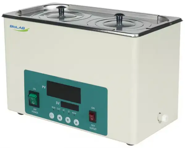
Water Bath BER-5204
- 1. Stainless steel stretching inner container and roof cover.
- 2. Intelligent temperature controller with PID program, digital tube display and function of timing and over-temperature protection.
- 3. the electric drain switch, one-button operation, convenient to drain,
- Note: single hole water baths have no drain function.
- 4. Power off when water shortage to ensure the safe operation of the product.
- Up to 3-Year Product Warranty
- US & EU Compliance Standards
- Door-to-Door Shipping
Technical Specifications
Detailed operating and construction parameters for this model.
| Model | BER-5204 |
| Classification | 2 rows & 6 holes |
| Heating Mode | Nature water convection heat transfer |
| Function | |
| --Temp. Range | RT+5~100°C |
| --Temp. Resolution Ratio | 0.1°C |
| --Temp. Motion | ±0.5°C |
| --Temp. Uniformity | ±1.0°C |
| Structure | |
| --Inner Chamber | Stainless steel |
| --Outer Shell | Cold-rolled steel plate, resistance to chemical reagents coating on the surface |
| --Heater | Stainless steel heating tube |
| --Power Rating | 1.5kW |
| Controller | |
| --Temp. Control Mode | PID |
| --Temp. Setting Mode | Touch button setting |
| --Temp. Display Mode | Measuring temperature displays on the three digital tubes upper row, set temperature displays on the lower row |
| --Timer | 0~9999 min (with timing wait function) |
| --Operation Function | Fixed temperature operation, timing function, auto stop |
| --Program Mode | Optional |
| --Additional Function | Deviation Correction, menu key locked, power failure back-up, power-off memory |
| --Sensor | NTC |
| Safety Device | Over temperature alarm |
| Specification | |
| --Inner Chamber Size (W*L*H)(mm) | 500*300*150 |
| --Exterior Size (W*L*H)(mm) | 524*322*210 |
| --Packing Size (W*L*H)(mm) | 600*390*280 |
| --Volume | 22.5L |
| --Load Per Rack | 5kg |
| --Shelf Number | 1 |
| --Power Supply (50/60Hz) Current Rating | AC220V/6.8A |
| --NW/GW (kg) | 7.5/9 |
Product Features
Key design, performance, usability, and safety advantages.
Applications Explore common laboratory, research, industrial, and process applications.
Used for precision constant temperature and auxiliary.
Operating Manual View instructions, operating procedures, safety information, and maintenance guidance.
1. Summary
2. Structure features
3. Main technical parameters
4. Working Conditions
5. Attentions
6. Temperature Controller Operation
8. Fault analysis
1. Summary
BER-5204 Water Bath is applicable for distillation, concentration, drying and thermostatic heating of medical units, universities and colleges, scientific research units and laboratories of industrial and mining enterprises like chemical printing and dyeing enterprises and pharmaceutical enterprises.
2. Structure features
1. The enclosure of the product is formed and machined by using high-quality steel plate. Static electric spraying process is adopted on the surface, which is sturdy and durable. The inner container is finished by the stainless steel stretching.
2. The liner and upper cover are made of high-quality stainless steel plate, featuring strong corrosion resistance.
3. U-shaped heating pipe is adopted for direct heating in water. The temperature rise is quick and the thermal loss is small.
4. Single-row digital display or intelligent temperature controller boasts simple operation and favorable application effect.
3. Main technical parameters
Model | BER-5204 |
Supply voltage | 200-240V/100-120V |
Power(W) | 1500 |
Temp-motion(°C) | ±0.5 |
Temp-range(°C) | RT+5~100 |
Senility of Temp Control(°C) | ≤±1 |
Display error(°C) | ≤±2.5 |
Chamber Size (mm) | 500x300x150 |
Products Size (mm) | 524x322x210 |
Packing Size(mm) | 600x390x280 |
N.W.(Kg) | 7.5 |
G.W.(Kg) | 9 |
Table 1
4. Working Conditions
1. Temperature ranges between 5~40°C;
2. Relative humidity less than 85% RH;
3. Power: voltage 220-240v, frequency 50-60Hz;
4. No violent vibration and corrosive gas surround the equipment.
5. Attentions
1. Before use, add water 50mm until the water reaches above the clapboard, then connect to power supply and heat. It is not allowed to heat with insufficient water.
2. During use, do not touch the heating pipe by your hands to avoid being scalded.
3. After use, timely discharge the water, dry it and keep it clean in order to extend the service life.
Operation:
1. Put the instrument horizontally.
2. Open the cover and add the water to the water tank, the water level must be higher than the heating pipe and temperature sensor.
NOTE: only pure water or only distilled water will cause the error warning (Er-1) by the Water level detection sensor. Add some Non-distilled water will solve this problem.
3. Connect the suitable power, and open the switch and the electricity supply.
4. The upper row of the instrument shows the test temperature and the set temperature is shown in the lower row.
5. Shot pressing the setting key can enter the setting state. Shift, plus and minus keys can adjust the temperature.
6. Press the upper key to set time, when the upper row shows ST and the lower row shows OFF, press the upper key again then the lower row shows the time. The shift key is used to change the numerical unit to is minute. There are two kinds of timing modes which are timing after the temperature constant and timing after the setting is finished. When the time arrived, the heating output stopped. If need to start the operation again, the power switch must be shut and opened again.
7. Automatic tuning function, If the test temperature fluctuation, the self-tuning function can adjust. Press the plus & minus keys till the indicator light is on.
6. Temperature Controller Operation

Figure 1
1) 【RUN】:When running, the light is lit, the end of the run, the light is off.
2) 【OUT】:The light is lit when the heating output.
3) 【AT】:When auto-tuning, the light flashes.
4) 【ST】:Start timing, this light is lit
5) 【ALM】:The light is lit when the over-temperature alarm.
1.Operation and using
1-1. When the controller is powered on, the up-row of the Display Window show the version number and the value of temperature range, the down-row of the Display Window show the max value of temperature setting, the controller will get into the normal view state after 2 seconds once powered on.
1-2. Temperature and Time Setting
1) Without Timing Function :
Press the "Set" button, get into the Temperature setting state, the display window show the prompt "SP" and the temperature set value, the users can edit the temperature setting value by using the "SHIFT", "DEC" and "INC" buttons; then press the "Set" button again, the controller will return to the normal view state, the setting value will be saved automatically.
2) With Timing Function :
Press the "SET" button in the non-set state, windows display the prompt "SP" and temperature set value. Re-press the "SET" button, windows display the prompt "ST" and time set value. Press the "SET" button again, controller will return to the normal display, the setting value will be saved automatically.
When the time is set to "0", it indicates the timer is inoperative, the controller will run continuously. If there is time set, the under window of controller will display temperature setting value or the running time according to the value of "ndt" ( In Parameter table 2). When display the running time, the unit decimal point is lit, When the runtime is over, the under window of controller will display "End", the buzzer will sound for "EST" ( In Parameter table 2) seconds, it can be muted by pressing any button, press the "RST" button for 3s at this time, the controller will restart.
1-3. Abnormal alarm for temperature measurement
If the up window of the controller show the prompt "---", it indicates that the temperature sensor has some faults or temperature exceeds the measuring range or the controller itself is faulty, the controller will cut off the heat-output automatically, the buzzer will sounds continuously, "ALM!" indicator light is lit on, Please check the temperature sensor and its wiring carefully.
1-4. When Over-temperature alarm, the buzzer beeps continuously, "ALM" warning light is lit, the Heat-Out is cut off. When the Under-temperature alarm, the buzzer beeps continuously, "ALM" warning light is flash. If the Over- temperature alarm is caused by the change of the temperature setting value, "ALM" warning light is lit, but the buzzer does not beep.
1-5. When the buzzer sounds, press any key to mute.
1-6. "SHIFT/AT" button: In the setting state, click the button to shift the set value. In the non-set state, keep pressing on the button for 6s, the controller will run the auto-tuning program.
1-7. "DEC/RST" button: In the setting state, click the button to reduce the set value. If you keep pressing on the button , the set value will reduce continuously.
In the normal state, when the timing work is over, press the button for 3s, the controller will restart to work .
1-8. "INC " button: In the setting state, click the button to increase the set value. If you keep pressing on the button, the value will increase continuously.
2.Auto-tuning of PID
In the non-set state, press the "SHIFT/AT" button for 6s, the controller will get into the pre-Auto-tuning state, the up window of the controller show the prompt "AT", the down window of the controller show the prompt "oFF", user can press the "DEC" or "INC" button to choose to show "oFF" of "on" prompt, when it shows the prompt "on", press the "SET" button, the controller will run the auto-tuning program, the "AT" light flashes, after auto-tuning end, the light stops flashing, parameter value is saved automatically. In the auto-tuning process, press the "SHIFT/AT" button for another 6s, the controller will stop the auto-tuning program.
During the Auto-tuning process, if Over-temperature alarms, the buzzer does not beep, "ALM" warning light is not lit, the Heat-Out will be cut off; the "SET" button is invalid, the under window always displays temperature set value.
3.Internal parameters settings
In the non-set state, Press the "Set" button for 3s, controller will display the password prompt "Lc". Adjust the password to the required value, then press the "Set" button again, it will run into the internal parameter setting state. If press the "Set" button for another 3s, it will return to the running state, the setting value will be saved automatically.
Parameter table 1
Prompt | Name | Instruction of the function | (Setting range) factory set value |
Lc | Password key | When Lc=3, enter the next parameters. | 0 |
ALH | Over-temp alarm | If "SV>(SP+ALH)", the "ALM" light turns on. The buzzer sounds and the heating output turns off. | (0~100.0°C) 5.0 |
ALL | Under-temp alarm | If "SV<(SP-ALL)", the "ALM" light flashes, the buzzer sounds. | (0~100.0°C) 0 |
P | Proportional band | Adjustment of proportional function. | (0.1~100.0°C) 6.0 |
I | Integration time | Adjustment of integration function. | (1~2000) 200 |
d | Differential time | Adjustment of differential function. | (0~1000) 200 |
T | Control cycle | The temperature control cycle. | (1~60) 5 |
Pb | Zero point adjust | When the zero error comparatively larger, to update this value should be needed. Pb= actual value - measure value | (-50.0~50.0°C) 0 |
PL | Full point adjust | When the full point error also comparatively larger, to update this value should be needed. PK=1000 x(actual value - measure value)/ measure value. | (-999~999) 0 |
Addr | null | ||
Loc | Setting Lock | 0:Enable to set temperature and time. 1:Disable to set temperature and time. | (0~1) 0 |
Table 2
Parameter table 2
Prompt | Name | Instruction of the function | (Setting range) factory set value |
Lc | Password key | When Lc=9, enter the next parameters. | 0 |
ndA | Temp alarm mode | 0: With over-temp alarm only. 1: With over-temp alarm and under-temp alarm at the same time. | (0~1) 0 |
ndc | control mode | 0: PID control, 1: ON/OFF control. | (0~1) 0 |
dE1 | Upper deviation | Valid only at ON/OFF control | (0~100.0°C) 0 |
dE2 | Lower deviation | (0~100.0°C) 0 | |
ndT | Timer mode | 0: No timer function. 1: Constant temperature timing 2: Run Timing | (0~2) 1 |
Hn | Timer unit | 0: Minute. 1: Hour. | (0~1) 0 |
SPd | Constant temp Deviation | When SP >= (SV - SPd ), the Controller get into the Constant-temp State | (0.1~100.0°C) 0.5 |
SPT | Const-Temp buzzer time | If get into the Const-Temp State, the Buzzer will beep for SPT seconds Note: if SPT=9999 it meas the buzzer will beep continuously. | (0~9999S) 0 |
EST | Timing Over Buzzer time | If the timing work is over, the Buzzer will beep for EST seconds. Note: if EST=9999, it means the buzzer will beep continuously. | (0~9999S) 60 |
EH | Whether to continue to control after timing | 0:cut off Heat-Out after timing 1:continue to control after timing | (0~1) 0 |
ndo | null | ||
oPn | null | ||
nP | Maximum power | Percentage of maximum power heating output. | (0~100%) 100 |
Co | Off point | If "SV>(SP+Co)", stop the heating output. | (0~100.0°C) 50.0 |
SPL | Minimum set point | The minimum temperature set point. | (0~50.0°C) 0 |
SPH | Maximum set point | The maximum temperature set point. | (SPL~100.0°C) 100.0 |
Table 3
Parameter table 3
Prompt | Name | Instruction of the function | (Setting range) factory set value |
Lc | Password key | When Lc=27, enter the next parameters. | 0 |
Fc | Temperature unit | 0:Centigrade; 1:Fahrenheit | (0~1) 0 |
Table 4
Parameter table 4
Prompt | Name | Instruction of the function | (Setting range) factory set value |
Lc | Password key | When Lc=567, enter the next parameters. | 0 |
rST | Reset to default values | 0: cancel to reset to default value; 1: confirm to reset to default value. | (0~1) 0 |
Table 5
4. Wiring

Figure 2
8. Fault analysis
Failure | Cause | Handling method |
No power supply | 1. Bad contact between plug and socket 2. The fuse is burnt. | 1. Replace the plug or socket tube. 2. Replace the fuse with same specification. |
No temp. rise | 1. The temp. Controller is broken 2. The sensor is broken 3. The set temperature is lower than water temperature 4. The heating pipe is burnt | 1. Replace the instrument 2. Replace the sensor 3. Reset the temperature 4. Replace the heating pipe |
The big difference between display temp. and actual temp. | 1. The temp. controller 2. The temp. sensor is broken. | 1. Replace the temp. controller 2. Replace the temp. sensor. |
Table 6