
Get Price
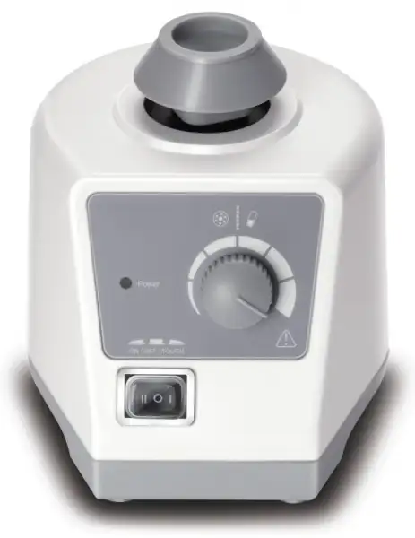
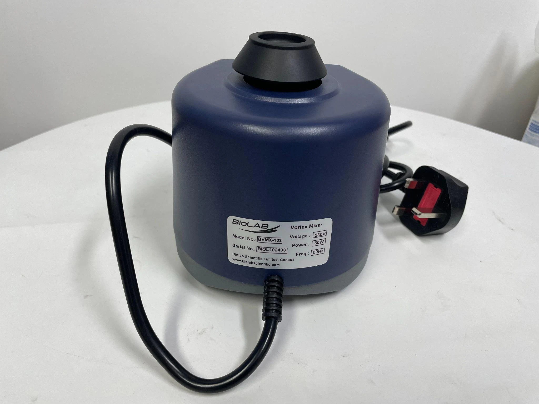
Vortex Mixer BVMX-103
- Variable speed of 0 to 3,000 rpm for gentle shaking to rapid mixing of samples
- Touch or continuous operation mode
- Includes a standard top head for mixing a single test tube or other small vessel up to 30 mm in diameter
- Electronic speed control maintains constant speed even during changes in load
- Steel base with specially designed vacuum suction feet provides stability and dampens vibration
- Robust aluminum-cast construction
- Up to 3-Year Product Warranty
- US & EU Compliance Standards
- Door-to-Door Shipping
Technical Specifications
Detailed operating and construction parameters for this model.
| Model | BVMX-103 |
| Voltage, Frequency | 100-120V/200-240V, 50/60Hz |
| Power | 60W |
| Mixing motion | Orbital |
| Orbital diameter | 4mm |
| Motor type | Shaded pole motor |
| Motor rating input | 58W |
| Motor rating output | 10W |
| Speed range | 0-3000rpm |
| Speed display | Scale |
| Run type | Touch operation/Continuous |
| Dimension [WxHxD] | 127 x 130 x 160mm |
| Weight | 2.0kg |
| Permissible ambient temperature | 5-40°C |
| Permissible relative humidity | 80%RH |
| Protection class | IP20 |
Product Features
Key design, performance, usability, and safety advantages.
Accessories For Purchase View compatible optional accessories and additional items available separately.
| Images | Name | Description |
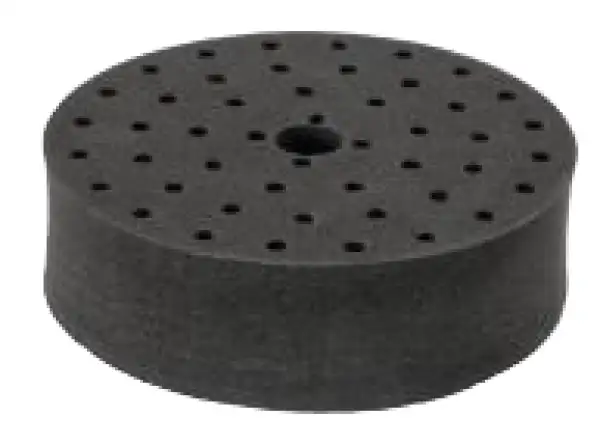 | tube adapter | for 48 holes test tubes, Ø6mm |
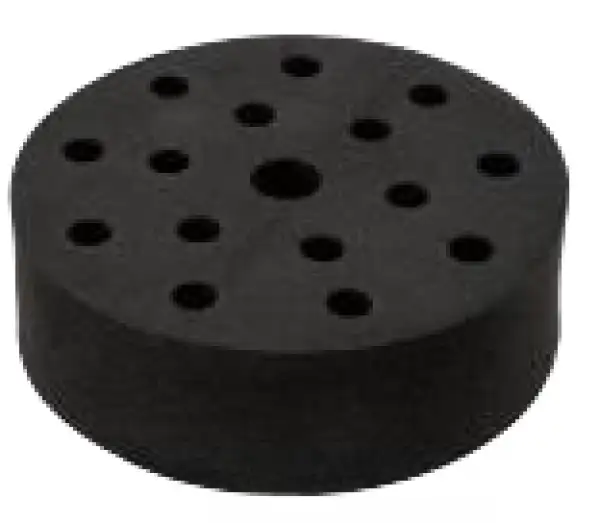 | tube adapter | for 15 holes test tubes, Ø10mm |
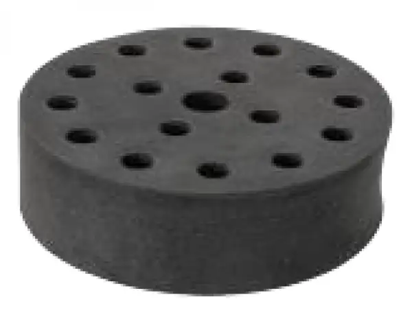 | tube adapter | for 12 holes test tubes, Ø12mm |
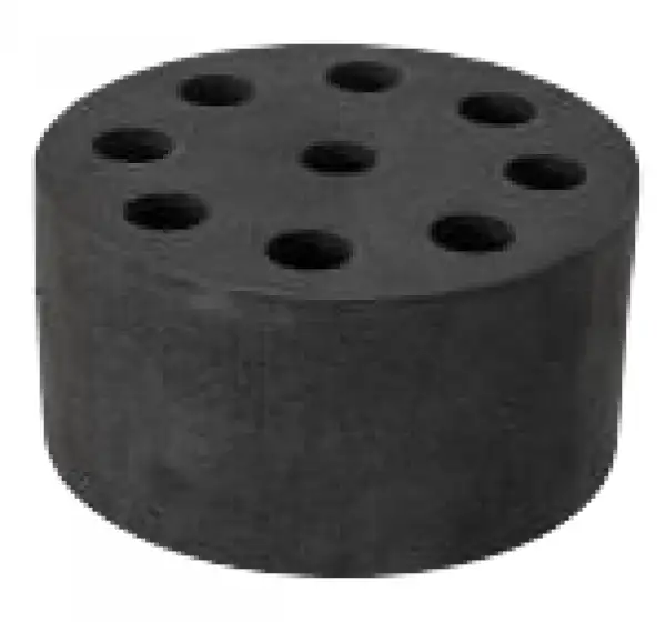 | tube adapter | for 8 holes test tubes, Ø16mm |
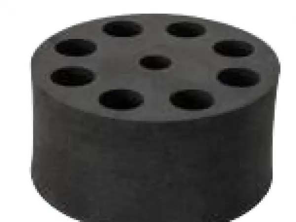 | tube adapter | for 8 holes test tubes, Ø20mm |
 | Platform pad | Ø99mm, multiple small tubes and vessels |
 | Vacuum chunk | Made of rubber |
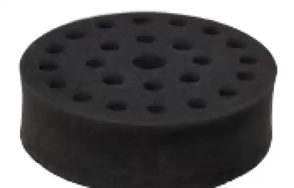 | tube adapter | for 24 holes test tubes, Ø10mm |
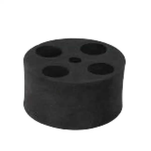 | Tube adapter | for 4 holes test tubes, Ø28mm (50mL) |
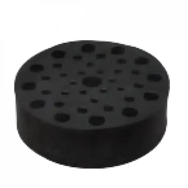 | Tube adapter | 12XØ9.8mm + 12XØ6.6mm + 12XØ5mm (1.5/2.0/0.5/0.2mL) |
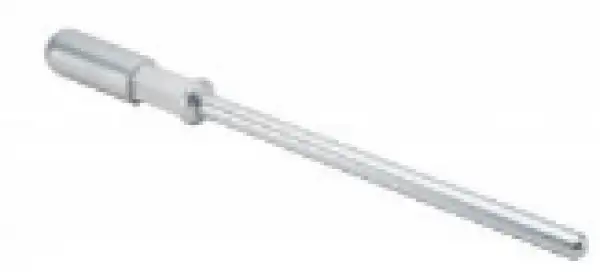 | Tube holding rod | used with tube adapters |
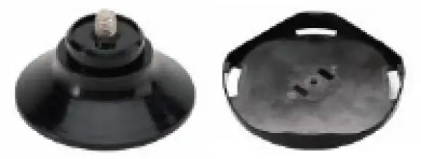 | Universal top plate | Ø100mm Includes 4 vacuum chuck |
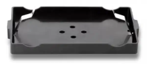 | Microplate clamp | Includes rectangle PCR tube adapter |
 | Large Platform Multi-Specimen Test Tube Adapter | 44 holes Ø5mm + 55 holes Ø6.6mm + 30 holes Ø9.8mm (1.5/2.0/0.5/0.2mL) |
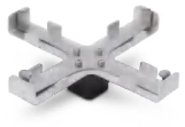 | Ampule/Tube Attachment | 4pc ampule/tube (0.2mL-15mL) |
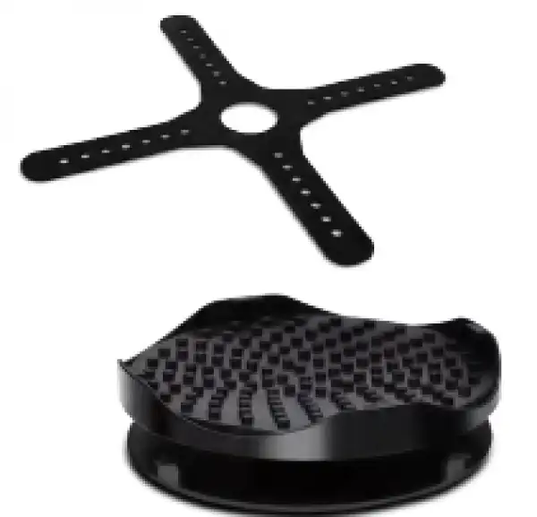 | Erlenmeyer flask attachment | 100mL-250mL, Operating speed: 0-1500rpm |
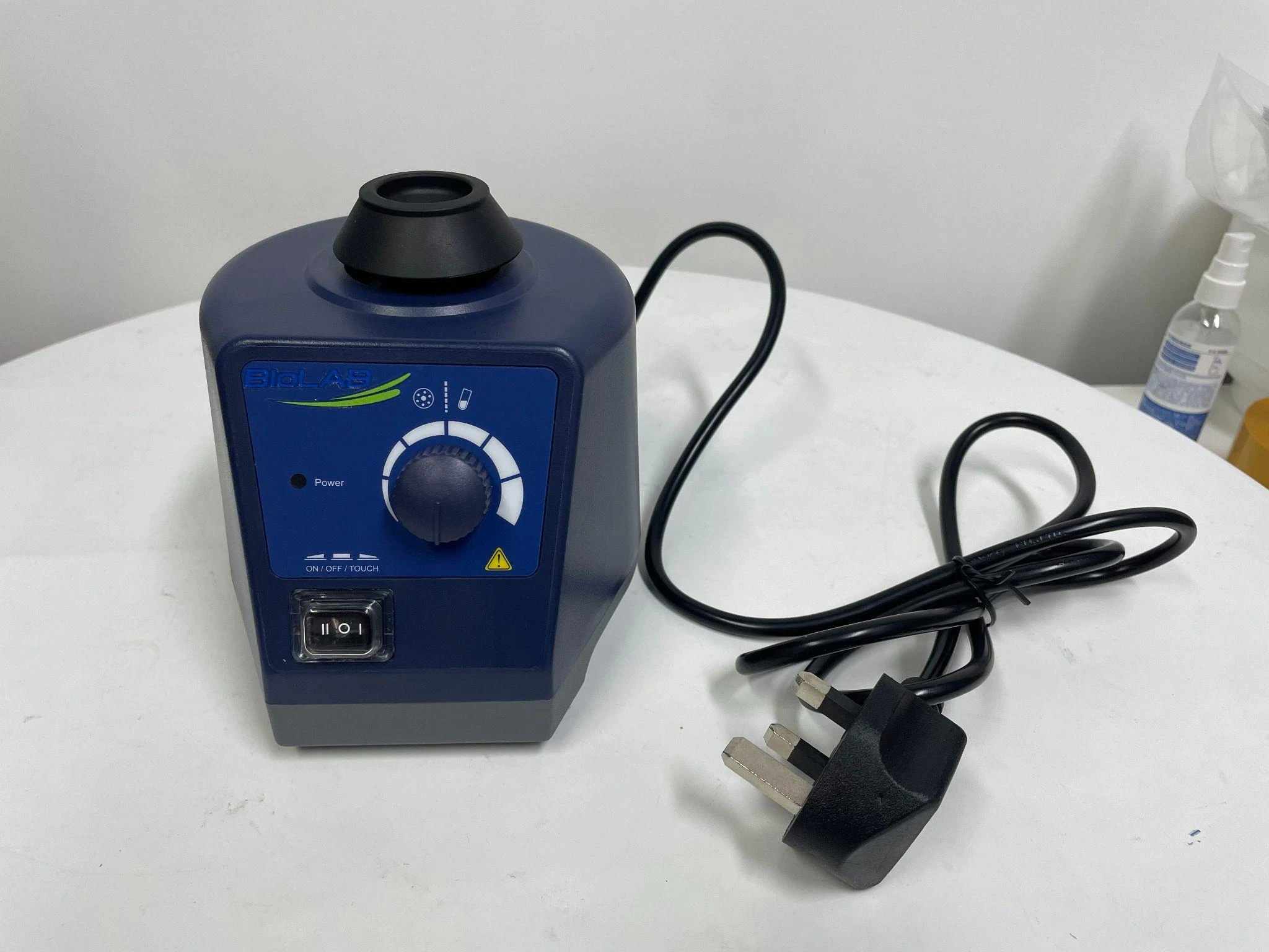
Product Photos View additional product images and select a thumbnail to enlarge it.
Operating Manual View instructions, operating procedures, safety information, and maintenance guidance.
1. Preface
2. Service
3. Warranty
4. Safety Instructions
5. Proper use
6. Inspection
6.1. Receiving Inspection
6.2 Listing of Items
7. Trial run
8. Operation
8.1 Continuous operating
8.2 Touch operating
9. Maintenance and Cleaning
10. Associated standards and regulations
11. Technical data
12. Applications
1. Preface
The "Vortex Mixer (Adjustable and Fixed Speed Models) User Manual". Users should read this manual carefully, follow the instructions and procedures, and beware of all the cautions
2. Service
When help needed, you can always contact the service department of manufacturer for technical support in the following way :
Please provide the customer care representative with the following information:
Serial Number (on the bottom panel)
Certification
Description of problem
Methods and procedures adopted once to resolve the problems
Your contact information
3. Warranty
This instrument is warranted to be free from defects in materials and workmanship under normal use and service, for a period of 12 months from the date of invoice. The warranty is extended only to the original purchaser. It shall not apply to any product or parts which have been damaged on account of improper installation, improper connections, misuse, accident or abnormal conditions of operation.
For claims under the warranty please contact your local dealer. You may also send the instrument directly to our works, enclosing the invoice copy and by giving reasons for the claim.
4. Safety Instructions
| Warning! Read the operating instructions carefully before use. Ensure only trained staff uses the instrument. |
| Protective ground contact! Make sure the socket is grounded before use. |


Table 1
Wear the personal safety items to avoid the risk from
Splashing of liquids.
Mechanical vibration may lead to glass breakage.
Trapping parts of the body, hair or pieces of clothing in the moving parts.
During manual manipulation:
Keep medium vessels vertical as much as possible.
Mix the medium in the minimum pressure required.
Use attachment supplied when mixing a mass of different medium.
Set up the instrument in a spacious area on a stable, clean, non-slip, dry and fireproof surface. Do not operate the instrument in explosive atmospheres, with hazardous
Put the speed control knob to the lowest position. Gradually increase the speed.
(adjustable speed model), reduce the speed if:
The medium splashes out of the vessel because of too high speed.
The instrument is not running smoothly or moves on the stage.
Safe operation is only guaranteed with the accessories described in the "Accessories" chapter.
Accessories must be securely attached to the instrument and can not come off by themselves.
Check the instrument and accessories before each use. Do not use damaged components.
Place a vessel at the center of the mixing head and spread out others uniformly.
A sharp edged vessel can wear-out the mixing head.
Always disconnect the plug before fitting accessories.
The instrument may heat up when in use.
The operating voltage required on the label and voltage supply network must match.
Protect the instrument and accessories from bumps and impacts.
The instrument may only be opened by qualified and trained technician.
5. Proper use
The instrument is designed for mixing liquids in schools, laboratories or factories. This device is not suitable for use in residential areas or other areas that may cause danger to the user or instrument.
6. Inspection
6.1. Receiving Inspection
Unpack the equipment carefully and check for any damages which may have arisen during transport. Please contact the manufacturer/supplier for technical support.
| Note: If there is any apparent damage to the system, please do not plug it into the power line. |

Table 2
6.2 Listing of Items
The package includes the following items :
Items | Qty |
Main unit | 1 |
User Manual | 1 |
Table 3
Please retain all packing materials. Additional shipping charges will be assessed if packing is unavailable for the system warranty service.
7. Trial run
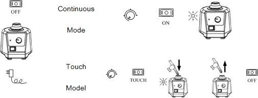
Figure 1
| Note: Ensure that the two-direction switch must be in the middle (off state) before powering on. |
Table 4
If these operations above are normal, the instrument is ready to operate following the "operation" chapter. If these operations are not normal, the instrument may be damaged. Please contact manufacturer/supplier for technical support.
8. Operation
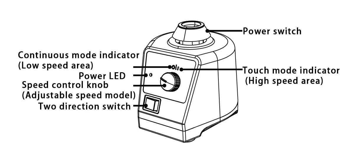
Figure 2
8.1 Continuous operating

ON

OFF
Place speed control knob at the lowest position. Put the instrument on a stable and safe place and plug in the main power.
Push the two-direction switch left to ON and power LED is lit.
Turn the speed control knob to set speed (Adjustable speed model).
Push the two-direction switch right gently to turn OFF.
8.2 Touch operating

Touch

OFF
Place the speed control knob at the lowest position. Put the instrument on a stable and safe place and plug in the main power.
Push the two-direction switch right to the touch mode.
Turn the speed control knob to set speed (Adjustable speed model).
If a test tube is pressed into the mixing head vertically, the instrument will begin to work and the power LED will be lit.
Push the two-direction switch left gently to OFF.
| Note: Place vessels as vertical as possible into the center of mixing head for proper mixing. Adjust the speed control knob slowly in order to have the instrument works smoothly. Don not run continuous operating mode at high speed area. |
Table 5
9. Maintenance and Cleaning
Proper maintenance can keep instrument working and extend its life time.
Do not spray the cleanser into the instrument when cleaning.
Unplug the power line when cleaning.
Only use cleanser as shown below:
Dyes | isopropyl alcohol |
Construction materials | water containing tenside/ isopropyl alcohol |
Cosmetics | water containing tenside/ isopropyl alcohol |
Foodstuffs | water containing tenside |
Fuels | water containing tenside |
Table 6
For materials which are not listed, please request information from manufacturer/supplier.
Before using other method for cleaning or decontamination, the user must ascertain with the manufacturer/supplier whether this method will not harm the instrument.
Wear the proper protective gloves during cleaning of the instrument.
| Note: Electrical instruments may not be placed in the cleansing agent. The instrument is a sophisticated electronic product, please avoid severe shaking during use and transportation. The instrument must be cleaned and put it into the initial packaging carton before sending for service, avoid contamination. Switch OFF the instrument and put it in a dry, clean, stable place at room temperature in long-term disuse |
Table 7
10. Associated standards and regulations
Construction in accordance with the following safety standards: |
EN 61010-1 |
Construction in accordance with the following EMC standards: |
EN 61326-1 |
Associated EU guidelines: |
EMC-guidelines: 89/336/EWG Instrument guidelines: 73/023/EWG |
Table 8
11. Technical data
Items | Specifications |
Voltage [VAC] | 220-230 / 110-120 |
Frequency [Hz] | 50, 60 |
Power [W] | 60 |
Shaking movement | orbital |
Orbital diameter [mm] | 4 |
Motor type | Shaded-pole motor |
Motor rating input [W] | 58 |
Motor rating output [W] | 10 |
Speed range [rpm] | 0-3000(Adjustable speed model) 3000(Fixed speed model) |
Speed display | Scale |
Run type | Continuous/touch operation |
Table 9
Changing attachment
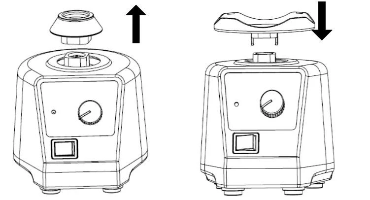
Figure 3
12. Applications
Attachments | Fixed speed model(2500rpm) | Adjustable speed model (0-2500rpm) | ||
Touch mode | Continuo us mode | Touch mode (High speed area) | Continuous mode (Low speed area) | |
VTI.1 | Y | Y | Y | Y |
VTI.2 + VT1.3.1 | Y | Y | ||
VTI.2 + VT1.3.2 | Y | Y | ||
VTI.2 + VT1.3.3 | Y | Y | ||
VTI.2 + VT1.3.4 | Y | Y | ||
VTI.2 + VT1.3.5 | Y | Y | ||
VTI.3 + VT1.3.6 | Y | Y | ||
VTI.3 + VT1.3.1 | Y | |||
VTI.3 + VT1.3.2 | Y | |||
VTI.3 + VT1.3.3 | Y | |||
VTI.3 + VT1.3.4 | Y | |||
VTI.3 + VT1.3.5 | Y | |||
Table 10