
Get Price
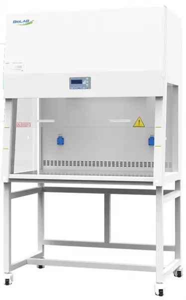
Vertical Laminar Airflow BDL-3501
- 1. Air return type structure design: Part of the clean air is recycled to reduce the operator's
- blowing feeling and prolong the life of the filter.
- 2. Product safety: the number of colonies is less than or equal to 0.5CFU/30min.
- 3. Filtration efficiency: For 0.3 μ m particles, the filtration efficiency can reach 99.995%.
- LCD display, display content: wind speed, time including the working time of the UV lamp and the working time of the filter.
- UV Lamp, Emission of 254 nanometers for most efficient decontamination.
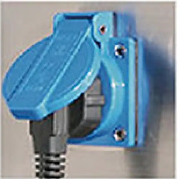
- Two splash proof sockets.
- Up to 3-Year Product Warranty
- US & EU Compliance Standards
- Door-to-Door Shipping
Technical Specifications
Detailed operating and construction parameters for this model.
| Model | BDL-3501 |
| Internal Size (W*D*H) | 1000*575*625mm |
| External Size (W*D*H) | 1100*710*1850mm |
| Airflow Pattern | Vertical laminar flow, return air |
| Applicable number of people | 1 |
| Work Surface Height | 750mm |
| Max Opening | 400mm |
| Air Velocity | 0.3~0.45m/s |
| Airflow Volume | 750m³/h |
| Noise | ≤65dB(A) |
| LED Lamp | 12W*1 |
| UV Lamp | 20W*1 |
| Power Supply | 220V±10%, 50/60Hz; 110V±10%, 60Hz |
| Consumption | 700W |
| HEPA Filter | 1 pcs |
| Gross Weight | 190kg |
| Package Size | 1240*980*1350mm |
Product Features
Key design, performance, usability, and safety advantages.
1. Air return type structure design: Part of the clean air is recycled to reduce the operator's
blowing feeling and prolong the life of the filter.
2. Product safety: the number of colonies is less than or equal to 0.5CFU/30min.
3. Filtration efficiency: For 0.3 μ m particles, the filtration efficiency can reach 99.995%.
LCD display, display content: wind speed, time including the working time of the UV lamp and the working time of the filter.

UV Lamp, Emission of 254 nanometers for most efficient decontamination.

Two splash proof sockets.
Operating Manual View instructions, operating procedures, safety information, and maintenance guidance.
1. Preface
2. Technical Parameters
3. Performance
3.1 Vibration
3.2 Illumination
3.3 Electrical safety
4.Product Features
4.1 Mechanical glass door control
4.2 Structure
5. Structure
5.1 Front glass door drive system
5.2 Air filtration system
5.3 UV light source
5.4 Lighting source
5.5 Waterproof socket
5.6 Control Panel
5.7 Fuse
6. Installation and Operation Instructions
6.1 Installation
6.2 Instructions for use
6.3 Contraindications
6.4 Operation conditions
7. Maintenance and Common Failure Analysis
7.1 Cabinet surface cleaning
7.2 Full maintenance cycle
7.3 Maintenance
7.4 Disinfection method
7.5 Common failure analysis
7.6 Storage conditions
7.7 Transport conditions
8. Precautions
9. Label Description
9.1 Fuse (fuse) label
9.2 Fluorescent lamp anti-shock label
9.3 Grounding label
9.4 Glass door height warning label
9.5 UV light warning label
9.6 Load requirement label
9.7 Precautions for glass use
10. Electromagnetic Compatibility
11. Warranty
1. Preface
Thanks for choosing Biolab medical vertical laminar flow cabinet. We sincerely hope that our products can bring you the greatest help in your work. In order to give you a better understanding of the medical vertical laminar flow cabinet, please read the instructions carefully before use. The content of this manual is very important for you to use this machine safely and correctly! Please keep this manual properly. Used by medical institutions for local work environment purification.
Working environment:
(1) Just for indoor use only;
(2) Ambient temperature: 15°C~35°C;
(3) Relative humidity: ≤75%;
(4) Atmospheric pressure range: 70 kPa~106 kP
2. Technical Parameters
This product belongs to a vertical laminar flow medical laminar flow cabinet. The basic technical parameters are as follows:
Model Technical parameter | BDL-3501 | BDL-3502 | BDL-3503 |
Dimensions | 1100*710*1850(mm) | 1500*710*1850(mm) | 1800*710*1850(mm) |
Operating area size | 1000*575*625(mm) | 1400*575*625(mm) | 1700*575*625(mm) |
Rated voltage | AC 220V | ||
Rated frequency | 50 Hz | ||
Rated power | 700W | 750 W | 900W |
Air flow rate | 0.30m/s~0.45m/s | ||
UV lamp power | 20W | 40W | 40W |
Fluorescent lamp power | 12W | 16W | 16W |
Filtration efficiency | 99.995%(diameter 0.3μm) | ||
Noise | ≤65dB(A) | ||
Motor power | AC 220V 50Hz | ||
Motor Power | 90W | ||
Motor speed | 2460rpm | ||
Filter specifications | 980*470*69(mm)*1 | 1380*470*69(mm)*1 | 1700*470*69(mm)*1 |
Period of use | 8 years | ||
Software release version | |||
Table 1
Note:1. The power consumption of the power supply includes the power of the load in the operating area (the total power of the load cannot exceed 500W);
2. The company reserves the right to change the design of the product. The design of the product is subject to change without notice.
3. Performance
3.1 Vibration
The net vibration amplitude of the laminar flow cabinet within the range of air flow velocity from 0.30m/s to 0.45m/s and the frequency between 10Hz and 10kHz should not exceed 5μm (rms).
3.2 Illumination
The average illuminance of the laminar flow cabinet should be no less than 300lx within the range of air flow velocity from 0.30m/s to 0.45m/s.
3.3 Electrical safety
The protective connection impedance of the plug connection equipment: the impedance between the protective conductor terminal and each accessible part that is specified to be connected by the protective connection shall not exceed 0.1Ω.
Dielectric strength test: After the dielectric strength test, there should be no breakdown or repeated arcing. Basic insulation: 1390V, 50Hz AC voltage, test for 5s.
4.Product Features
4.1 Mechanical glass door control
The front glass doors and windows are controlled by the counterweight. The glass doors and windows can be stably parked at any height within the range, so that the glass door can also be controlled to take out the test products or instruments in the operating area when the power is off.
4.2 Structure
4.2.1 Clean bench classification: vertical laminar flow, single-sided operation;
4.2.2 Air return structure design: Part of the clean air is recycled to reduce the operator's blowing feeling and scientifically extend the filter life.
4.2.3 Filtration efficiency: The filters are all high-efficiency filters without partitions, and the filtration efficiency for particles with a diameter of 0.3μm is 99.995%;
4.2.4 It has a pre-filter that can effectively intercept large particles and impurities, effectively extending the service life of the high-efficiency filter;
4.2.5 The 7° inclination design of the front window of the operation is in line with the principles of ergonomics and reduces the operator's sense of oppression;
4.2.6 The work area table is made of high-quality 304 brushed stainless steel, which is beautiful, easy to clean and corrosion-resistant;
4.2.7 The cabinet is made of high-quality cold-rolled steel plate electrostatically sprayed, which is beautiful and stable;
4.2.8 The control panel adopts a touch switch, and the buttons are composed of fan button, lighting button, UV button, power button, socket button, air volume reduction button, and air volume increase button, which are easy to operate; the display screen displays: fan wind speed, display time, UV lamp working time, filter working time;
4.2.9 Primary and high-efficiency filters can be performed on the front side of the cabinet without moving the equipment;
4.2.10 The front window of the clean bench is a manual window made of 5mm thick tempered glass, glass door-counterweight structure, with anti-falling design, flexible and convenient to open up and down, and hover at any height within the travel range;
4.2.11 The fan has 8 speed settings to suit different types of experiments;
4.2.12 The UV lamp has an interlocking function with the fan and fluorescent lamp, that is, when the fan and fluorescent lamp are working, the UV lamp cannot be turned on to protect the operator;
4.2.13 It has a UV lamp and fan reservation timing function;
4.2.14 It has a pressure unit conversion function to switch between PA and m/s;
4.2.15 The UV lamp opening delay is adjustable between 5 and 20 seconds to protect the operator's safety;
4.2.16 Complete alarm system:
1. Set the front window opening safety height, and alarm when it is lower than or higher than the safety height to ensure stable performance during equipment use;
2. Filter pressure over-high alarm: alarm when the filter resistance becomes larger;
3. Filter failure replacement alarm: when the filter life expires, there will be a filter replacement alarm;
4. Wind speed alarm: alarm when the airflow fluctuation of the clean bench is lower than 20% of the nominal value;
4.2.17 Foam caster design, convenient for cabinet movement and fixation.
5. Structure
The product is composed of cabinet, fan, high efficiency filter, caster, lighting lamp, UV lamp and control system.
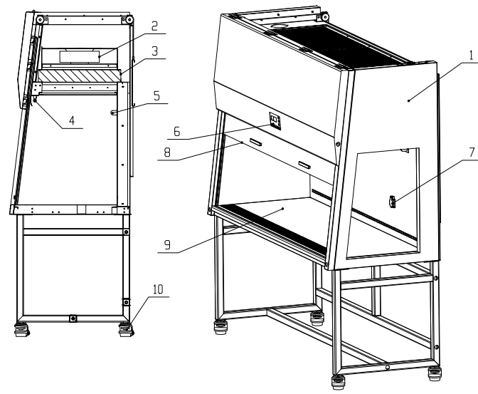
Figure 1
1. Cabinet
2. Fan
3. High efficiency filter
4. Fluorescent lamp
5. UV lamp
6. Display screen
7. Socket
8. Front window glass
9. Working desk
10. Fuma casters
5.1 Front glass door drive system
The front glass door drive system is composed of counterweights, front glass doors, etc.
5.2 Air filtration system
The air filtration system is the most important system to ensure the performance of this equipment. It consists of a fan and an air filter. The main function of the air filtration system is to continuously bring clean air into the operation area to ensure that the air flow velocity in the operation area and the cleanliness in the operation area meet the standard requirements.
5.3 UV light source
The UV lamp tube is located inside the operation area to ensure that the ultraviolet light can be fully irradiated to all spaces in the operation area and fully disinfected.
5.4 Lighting source
Illuminating LED lights to ensure that the average illuminance in the operating area meets the standard requirements.
5.5 Waterproof socket
A waterproof socket (IP44) is installed in the operation area, which can supply power to the equipment in the operation area.
 1. The total power of the equipment used on the two sockets does not exceed 500W (rated voltage*rated current 220V*2.3A);
2. The waterproof socket can only be waterproof when its front cover is down. When the front cover is opened, the socket cannot be regarded as a waterproof socket.
Note: IP44 is the socket protection level. According to the provisions of GB4208: Prevent fixed foreign objects with a diameter of not less than 1.0mm from entering the socket housing and contacting internal parts;Prevent splashing water from entering, prevent splashing water from all directions from entering the socket and causing damage.
5.6 Control Panel
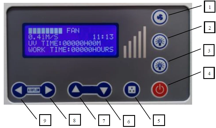
Figure 2
1 | Fan button | 5 | Socket button |
2 | Lighting lamp button | 6,7 | Function setting debugging button |
3 | UV lamp button | 8 | Air flow decrease button |
4 | Power button | 9 | Air flow increase button |
Table 2
a. Gear display
Through the gear display, you can understand the wind speed gear situation when the laminar flow cabinet is working.
b. Button description
The operation of the laminar flow cabinet needs to be realized by tapping the buttons.
(1) | | Power button | The main switch that controls other function button.Each time you press the button, the buzzer will sound and the LCD screen will change state, from dark to bright or from bright to dark. The system will also switch between standby mode and working mode. |
(2) | | Fan button | It is the control key for the working status of the fan. Each time you press it, the working status of the fan and the corresponding indication status on the LCD display will change once. The fan has a memory function, that is, the fan will display the fan position when it was last turned off when it is turned on next time. The fan cannot be started when the glass door is closed. |
(3) | | Lighting button | Each time you press, the state of the lighting tube changes once, that is, from off to bright, and from bright to off. |
(4) | | UV lamp button | Control button for UV lamp. Each time you press it, the status of the UV lamp and the corresponding indication status on the LCD display will change once, either from bright to off, or from off to bright. (The UV lamp is interlocked with the fan, light lamp, and front window glass, that is, when the lighting, fan, and front window glass are turned on, the UV lamp is automatically turned off) |
(5) | | Socket button | The control key of the socket on and off the working state. Each time you press, the on-off status and the corresponding indication status on the LCD display will change once. |
(6) | | Airflow decrease button | When the fan is running, if the number of "▊" is greater than 1, each press can reduce the wind speed by one gear, and the buzzer will sound once until 1 "▊" appears. When the UV lamp is turned on, press this key to reduce the UV lamp timing time, the minimum time is 10 minutes, and the set time can be memorized. |
(7) | | Air flow increase button | When the fan is running, if the number of "▊" is less than 8, each time you press it, the wind speed can be increased by one gear, and the buzzer will sound once, until "▊▊▊▊▊▊▊▊" appears. When the UV lamp is turned on, press this button to increase the UV lamp timing time, with a maximum time of 90 minutes, and the set time can be memorized. |





Table 3
8. Display screen: After turning on the power, the display contents are shown from top to bottom: ▊▊▊▊▊▊▊▊▊FAN, indicating the working wind speed of the fan; the corresponding wind speed under the current state is displayed below; the time is displayed on the right (the adjustment of the time will be explained below); UV TIME is the working time of the ultraviolet lamp of this device; WORK TIME is the working time of the filter of this device.
9. Clock adjustment: In standby mode, press and hold the lighting key  to enter the clock setting mode. The hour digit starts to flash. Press the fan speed increase and decrease keys
 (number 8 and 9) to adjust the clock size. Then press the fan key. The minute digit
starts to flash. Press the fan speed increase and decrease keys  (number 8 and 9) to adjust the minute digit. When both the minute and hour digits are adjusted to the current time, press and hold the lighting key again to save the clock after an alarm sounds.
10. Adjustment of UV lamp timing: Press the UV lamp button  to turn on the UV lamp. Press the wind speed up button
 or the wind speed down button
 to adjust the UV lamp timing. The timing can be adjusted within the range of 0-90 minutes.
11. Pressure unit conversion: Turn on the fan button  then press and hold the UV button for 3 seconds to switch the unit between PA and m/s.
12. UV fan scheduled timer switch: In standby mode, long press No. 7 button  to enter the timing interface. In the timing interface, press the fan button to shift (the digit to be set will flash at this time); press No. 8, 9 fan speed increase and decrease buttons to operate the set time. Press the socket button
 to switch between UV and fan timing. After setting the time period, long press No. 7 button to save. In the scheduled timing state, long press No.2 lighting button to return to zero to cancel the timing function.
Note: When there is a scheduled timer, the display screen will show *, and when there is no scheduled timer, the display screen will not show *.
13 Alarm function switch: In standby mode, press and hold the fan speed down button to enter the alarm function switch interface, press the No. 7 button and the No. 6 button to select the alarm function option, and press the fan speed up button to turn on (on) or off (off). After the setting is completed, press and hold the fan gear increase button to save.
Note: Alarm function instructions: E1-front window is not at a safe height alarm; E2-overpressure alarm; E3-low wind speed alarm; E4-filter replacement reminder alarm; E5-UV lamp replacement reminder alarm;
5.7 Fuse
The laminar flow cabinet is equipped with a power fuse, which is located on the side of the power cord outlet on the side of the box. For the corresponding specifications and models of the fuse, please refer to the section 9. Label description.
6. Installation and Operation Instructions
6.1 Installation
a. Remove all packaging components.
b. Check whether there are scratches, deformations or foreign objects on the outer surface of the host.
c. Check the relevant accessories and information carefully according to the packing list of the accessories in the manual.
d. Move the entire equipment to a site as close as possible to the final location and convenient for installation.
Note:
The base part is placed at the back of the laminar flow cabinet during transportation, and it should be taken out before installation; it is strictly prohibited to move the laminar flow cabinet with the bottom facing upwards, and it is strictly forbidden to place or disassemble it.
e. Assembly of base part
For the specific assembly process of the base, please refer to the installation diagram of the base, as shown in below figure.
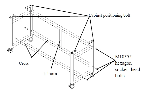
Figure 3
Unscrew the M10x55 hexagon socket head bolts in the cross brace and T-shaped brace, and assemble the base according to the above figure. It is required to be fastened firmly.
f. Fuma caster adjustment
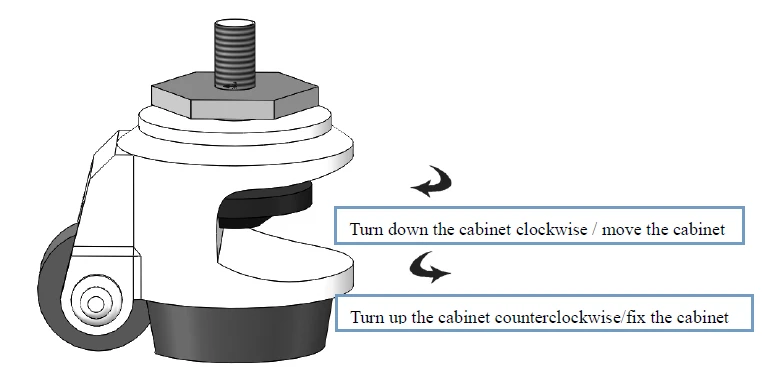
Figure 4
Rotate the red part of the Fuma casters clockwise to lower the corresponding base feet and lower the cabinet height. The four Fuma casters can be lowered at the same tim e to move the cabinet position; rotate the red part of the Fuma casters counterclockwise to raise the corresponding base feet. Increase the height of the cabinet, four Fuma casters can be adjusted at the same time to fix the cabinet; the four Fuma casters can be adjusted at the same time to make the cabinet in a horizontal and stable state.
g. Connect the host and base Refer to the figure below to connect the host and the base
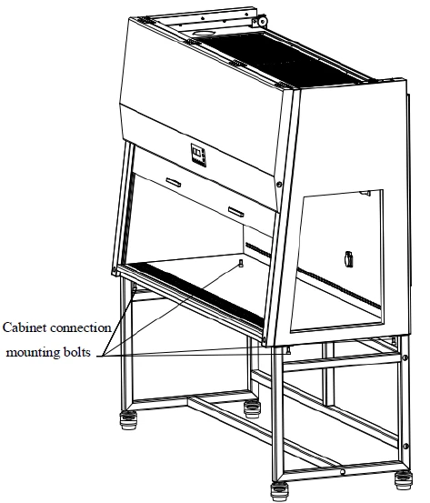
Figure 5
As shown in the figure above, use M10x20 hexagon socket head bolts, flat washers 10, and spring washers 10 to pass through the base and side plates from bottom to top and fasten them firmly.
h. Remove the counterweight fixing screws and silicone strips
Before the first use, please use a cross screwdriver to remove the fixing bolts on both sides of the counterweight at the rear of the cabinet, then lift the front window glass, and then remove the silicone strip under the front window glass.
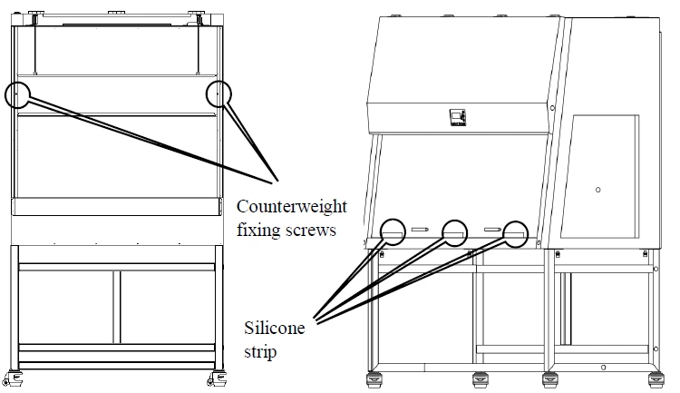
Figure 6
i. Placement of the whole machine
The medical laminar flow cabinet should be placed in an airflow protection area to prevent the airflow caused by the ventilation system, air conditioning, doors, windows, and personnel movement from affecting the medical laminar flow cabinet. Do not place the workbench in a position that is difficult to operate and disconnect. At least 300mm of space must be reserved on each side of the medical laminar flow cabinet for inspection.
1) When installing the cabinet, it should be in a large and open place;
2) When moving the cabinet, you need to cut off the power supply and adjust the casters before moving slowly;
3) The spare long counterweight in the packing box must be kept properly. When the pulley is used for a long time, the glass and the counterweight may appear unbalanced. At this time, it can be used to adjust the balance between the counterweight and the glass;
6.2 Instructions for use
a. Connect to power;
b. Press the relevant function key (refer to the description in 5.5 for relevant keys, functions and operations);
c. Before using, lower the bottom edge of the glass door to the bottom, turn on the UV lamp, and sterilize for more than half an hour;
1)When disinfecting, people should leave the room to protect eyes and skin and avoid injury caused by accidental exposure;
(2)The intensity of the UV lamp is tested regularly according to the manufacturer's specifications, it is recommended to be quarterly, if it fails, it will be replaced;
Lift the bottom edge of the glass door to a suitable height, turn on the fan, and run for half an hour before normal operation in the cabinet can be performed;
In order to ensure the safety of the operation, please put the experimental supplies in the laminar flow cabinet in advance.
e. After using, lower the bottom edge of the glass door to the bottom, turn on the UV lamp, disinfect for more than half an hour, and then turn off the equipment.
6.3 Contraindications
No.
6.4 Operation conditions
The laminar flow cabinet can protect the sample during use, but does not protect the operator and the environment, so the operator needs to wear protective clothing, masks and medical rubber gloves for personal protection during the operation.
7. Maintenance and Common Failure Analysis
Since the statistics of operating time will directly affect the judgment of maintenance needs, we
recommend that a detailed record of operating time should be prepared when using this equipment for reference and inquiries
7.1 Cabinet surface cleaning
7.1.1 Surface cleaning of operating area
Wipe the entire surface with a soft cotton cloth soaked in concentrated soap solution, then use
another cotton cloth or towel soaked in clean hot water or warm water to wipe off the soap, and then quickly dry it with a dry cloth or towel. Use medical alcohol or other disinfectants to clean the work surfaces that are contaminated or have traces.
 The disinfectant used must not damage 304 stainless steel
7.1.2 External surface and glass door cleaning Any non abrasive household cleaner, use a soft cotton cloth or towel to clean
7.2 Full maintenance cycle
The recommended overall maintenance cycle is one year or 1000 working hours
7.3 Maintenance
7.3.1 Daily or weekly maintenance
a. Disinfection and cleaning of the operation area (refer to 7.1.1 instructions)
b. Clean the external surface around the operating area and the g lass door (refer to 7.1.2
instructions)
c. Check whether the various functions of the device are abnormal
d. Record this maintenance
7.3.2 Monthly maintenance
a. Clean the external surface and glass door (refer to 7.1.2 instructions);
b. Wipe the work surface of t he equipment, the wall surface of the operation area (excluding the
operation area even wind net), and the inner surface of the glass door with 70% medical alcohol or a household bleach diluted 1:100 (ie 0.05% sodium hypochlorite), and then use it Wipe again with sterile water to remove residual chlorine
c. Check whether the various functions of the device are abnormal
d. Record this maintenance
7.3.3 Annual maintenance
a. Check that the tightness of the front glass door drive device is consistent
b. Check UV lamp and fluorescent lamp
c. Apply for testing the overall performance of the medical laminar flow cabinet every year to
ensure the safety of the medical laminar flow cabinet . The testing cost is the responsibility of the user
d. Record this maintenance
7.4 Disinfection method
For specific disinfection methods, please refer to the recommended disinfection procedures in
Appendix B of "YY0569 2011 Class II Biological Safety Cabinet"
7.5 Common failure analysis
7.5.1 Common failure analysis
Before diagnosing the fault, please confirm whether the power supply is connected, whether the
power cord is obviously damaged, whether the fuse is in good condition, and whether the switch is on
Failure phenomenon | Check parts | Solution |
LED light does not light up or abnormal | Light tube | Replace the lamp |
line | Check the line | |
Control panel | Replace the control board | |
UV lamp does not turn on or is abnormal | Chain | Confirm whether the fan and lighting are off |
Lamp holder | Check that the lamp tube and the lamp holder are firmly connected | |
Light tube | Replace the lamp | |
Ballast | Replace the ballast | |
line | Check the line | |
Control panel | Replace the control board | |
Buttons don't work | Control panel | Make sure that the power supply is connected and the fuse is intact |
Make sure the keys are not damaged | ||
Make sure the connection line is not in bad contact | ||
Replace the control board | ||
The device is not powered | Power supply | Power is not connected |
Power cable | Whether the power cord is obviously damaged | |
Fuse | Whether the insurance tube is good | |
Transformer | Whether the transformer output is normal | |
Control panel | Replace the circuit board | |
The display does not light up | Connect the cable | Check whether the connection cable is in good contact |
Display screen | Check if the display is good | |
Control panel | Replace the circuit board |
Table 4
1) The operation of the above electrical components must be carried out by a qualified electrician under safe conditions (cut off the power supply). All other parts are not allowed to be disassembled, otherwise the consequences will be borne by the user;
(2) When the equipment has a failure other than the above, and the operator cannot eliminate it immediately, please notify the maintenance department of our company immediately. For your safety, please do not repair the equipment by yourself;
(3) The maintenance of this equipment can only be undertaken by trained and approved technicians;
(4) If you need to order parts, you can find our technical service department, please indicate the model and serial number of the medical laminar flow cabinet you purchased.
7.5.2 Simple parts replacement
1) Replace the fuse
Socket fuse(Φ5*20(5A))located outside the right side of the laminar flow cabinet,when replacing, first turn off the power and unplug the plug, use a Phillips screwdriver to press and twist the fuse holder counterclockwise, remove the fuse in the fuse holder and replace it with a new fuse, and then press the fuse holder clockwise Just screw it on; the live wire fuse (Φ5*20 (10A)) is also located on the right side of the cabinet. Use a flat-blade screwdriver to lift the fuse holder and replace it with a new fuse, then press it back.
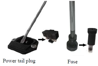
Figure 7
2) Replace the UV lamp
The UV disinfection lamp (T8 40W) equipped on the product has a service life of 600 hours. In order to achieve a good disinfection effect, it is recommended that you regularly test the UV intensity. You can use the UV intensity test card to confirm whether the UV l amp needs to be replaced. When replacing, first disconnect the power supply, then turn the lamp tube 90° to remove it, take the same specification UV tube, put it on the lamp holder and turn it 9 0° in the opposite direction.
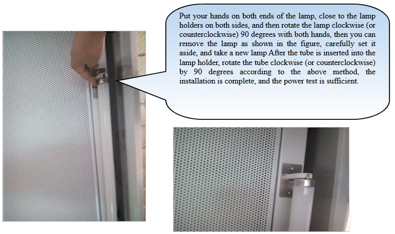
Figure 8
1) Replace the light
When the fluorescent lamp of the laminar flow cabinet needs to be replaced, please disconnect the power.Then remove the LED integrated bracket at an angle, unplug the right plug, replace it with a new LED bracket, and insert it into the card slot at an angle.
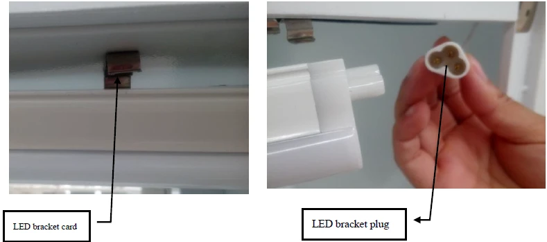
Figure 8
(1) It is forbidden to wipe the lamp body with a damp cloth when cleaning under power;
(2)It is forbidden to replace when the power is on;
7.6 Storage conditions
The medical laminar flow cabinet is stored at a relative humidity not exceeding 75%,the temperature is below 40°C,in a warehouse with good ventilation and no corrosive gases such as acids and alkalis,storage period should not exceed one year,medical laminar flow cabinet for more than one year for unpacking inspection,medical laminar flow cabinet that pass the unpacking inspection can enter the circulation field.
7.7 Transport conditions
Corresponding measures should be taken in accordance with the requirements of the external surface of the packaging box during the transportation of the medical laminar flow cabinet.The purchaser should carefully check the integrity of the packaging box when receiving the medical laminar flow cabinet with packaging box sent by the logistics company. If the packaging box is damaged, squeezed, etc., please refuse to sign for receipt, and contact our company in time.
When the laminar flow cabinet that has been installed and used is moved or moved again, please contact our company in time.
8. Precautions
1) Before connecting the AC power supply, make sure that the voltage of the power supply is consistent with the input voltage of the medical laminar flow cabinet and the voltage is stable, and ensure that the rated load of the power socket is not less than the requirement; this medical laminar flow cabinet uses a grounding plug, which has The third pin can only be used with a grounded power socket. This is a safety device. If the plug cannot be inserted into the socket, please ask an electrician to install a grounded power socket. Make sure that the grounding is good when using it;
(2) During the use of the equipment, do not place soft and subtle items (such as soft tissues) on the table to prevent them from being sucked into the negative pressure air duct and fan by the suction port, which will affect the operation of the equipment;
(3) The maximum weight of items placed in the cabinet should not exceed 23Kg/25x25cm2;
(4) Avoid vibration: Try to avoid the use of vibrating instruments (such as centrifuges, vortex oscillators, etc.) in the cabinet, because vibration will shake off the particulate matter accumulated on the filter membrane and reduce the cleanliness of the operating area. At the same time, if the balance of the front operating surface fails, it will also cause the contamination of the medical laminar flow cabinet to the operator;
(5) Open flames are forbidden: open flames are forbidden in medical laminar flow cabinet! During the use of an open flame, the air flow in the operation area will be disordered and the filter will be damaged. High temperature disinfection and sterilization are required during the experiment. It is strongly recommended to use an infrared sterilizer;
(6) High-efficiency filters have a service life. With the extension of the service life, the accumulation of dust and bacteria on the filter will cause the pressure loss of the high-efficiency filter to increase. When the wind speed cannot meet the requirements, you must contact our company's service department in time Contact, replace the high-efficiency filter, otherwise it will affect the safety performance of the equipment. The replaced filter shall be treated as medical waste;
(7) The fan and the steel plate on the lower side are the static pressure box cover. These air ducts are strictly sealed before leaving the factory. The airtightness must be maintained. The operator must not loosen or remove the screws of these parts,If there is a special need, it must be handled by the company's service staff;
(8)The storage period of the equipment is one year. If the storage period is exceeded, the company's technicians must open the box and inspect it once, and then use it only after it is qualified;
Solemnly reiterate: If the equipment is not used in accordance with the method specified by the company, the protection provided by the equipment may be damaged, and the company does not bear its responsibility for the risks caused by the non-compliant operation!
9. Label Description
9.1 Fuse (fuse) label
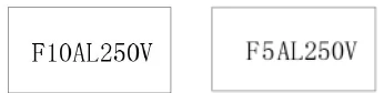
Figure 9
Fuse label
9.2 Fluorescent lamp anti-shock label
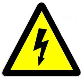
Figure 10
9.3 Grounding label

Figure 11
9.4 Glass door height warning label

Figure 12
9.5 UV light warning label

Figure 13
9.6 Load requirement label
(Note: The total load power of the two sockets cannot exceed 500W)
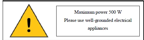
Figure 14
Note:Documents need to be consulted in all cases marked with this symbol( ) ),in order to
understand the nature of the potential hazards and any countermeasures that must be taken
9.7 Precautions for glass use
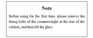
Figure 17
10. Electromagnetic Compatibility
1. This equipment complies with the emission and immunity requirements specified in GB/T
18268.1 2010
2 This equipment is designed and tested according to Class A equipment in GB 4824. In a home
environment, this device may cause radio interference, and protective measures need to be taken.
10.3 It is recommended that the equipment evaluate the electromagnetic environment before using. It is forbidden to use this equipment near strong radiation sources (such as unshielded radio frequency sources), otherwise it may interfere with the normal operation of the equipment
11. Warranty
11 .1 The warranty period is twelve months from the date of purchase (excluding lamps and fuses)
11.2 If the instrument and equipment during the warranty period become invalid or damaged due to improper use by the user, the company will not undertake the warranty obligation
11.3 After the warranty period, the company is also responsible for repairs, but the corresponding repair fees will be charged
11.4 The service life of the equipment is 8 years, and the production date is shown on the product label
11.5 Provide equipment drawings and some necessary technical data to maintenance organizations and maintenance personnel trained a nd approved by the company
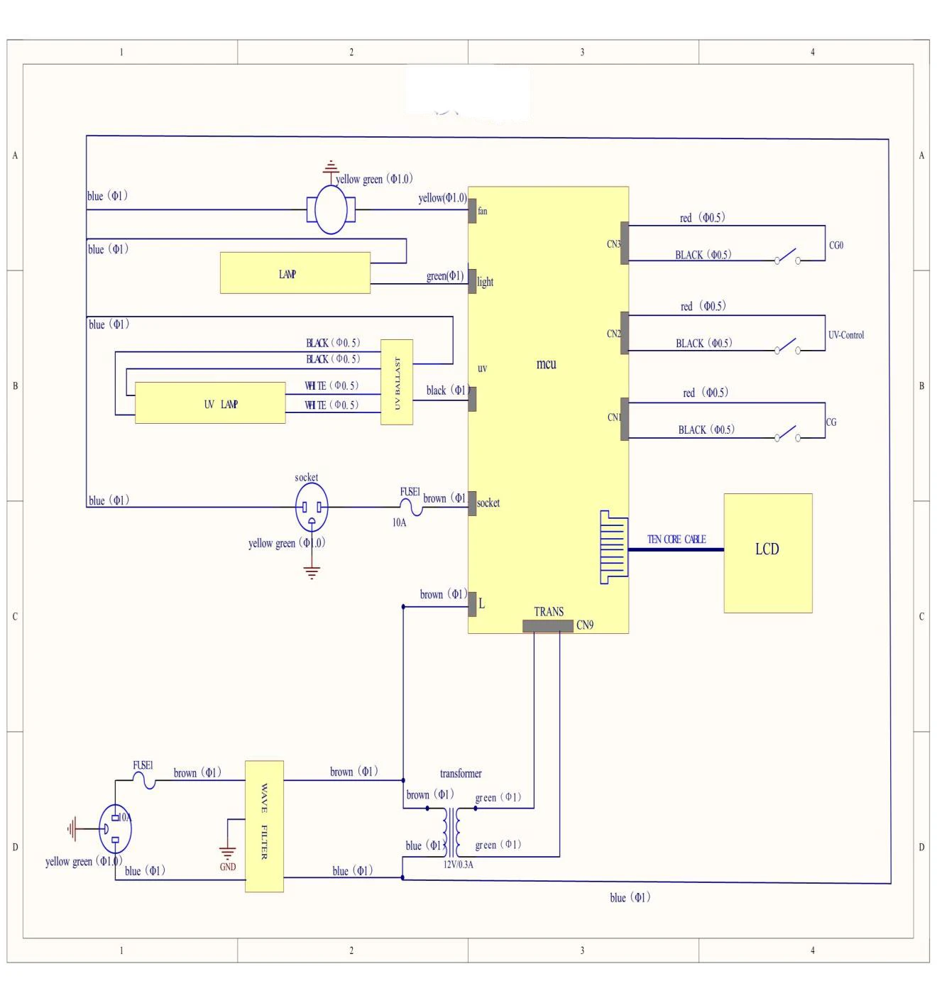
Figure 18
BDL-3501 packing list
Name | Quantity |
BDL-3501 Host | 1 set |
BDL-3501 Base | 1 set |
RVV power cable | 1pc |
Fuse(10A) | 1pc |
Fuse(5A) | 1pc |
UV tube(T8 20W) | 1pc |
BDL-3501 manual | 1pc |
Inspection Report | 1pc |
Certificate of conformity | 1pc |
Warranty Card | 1pc |
Hexagon socket head bolt M10*20 | 5 set |
Flat washer 10 + spring washer 10 | 5 set |
Allen wrench | 1pc |
Button plug (white) | 7pcs |
Counterweight | 3pcs |
Hexagon head combination screw with flat washer and spring washer M4*16 | 5 set |
Flat washer 4+spring washer 4+nut 4 | 5 set |
Table 5
BDL-3502 packing list:
Name | Quantity |
BDL-3502 Host | 1 set |
BDL-3502 Base | 1 set |
RVV power cable | 1pc |
Fuse(10A) | 1pc |
Fuse(5A) | 1pc |
UV tube(T8 40W) | 1pc |
BDL-3502 manual | 1pc |
Inspection Report | 1pc |
Certificate of conformity | 1pc |
Warranty Card | 1pc |
Hexagon socket head bolt M10*20 | 5 set |
Flat washer 10 + spring washer 10 | 5 set |
Allen wrench | 1pc |
Button plug (white) | 7pcs |
Counterweight | 4pcs |
Hexagon head combination screw with flat washer and spring washer M4*16 | 3 set |
Flat washer 4+spring washer 4+nut 4 | 3 set |
Table 6
BDL-3503 packing list:
Name | Quantity |
BDL-3503 Host | 1 set |
BDL-3503 Base | 1 set |
RVV power cable | 1pc |
Fuse(10A) | 1pc |
Fuse(5A) | 1pc |
UV tube(T8 40W) | 1pc |
BDL-3503 manual | 1pc |
Inspection Report | 1pc |
Certificate of conformity | 1pc |
Warranty Card | 1pc |
Hexagon socket head bolt M10*20 | 5 set |
Flat washer 10 + spring washer 10 | 5 set |
Allen wrench | 1pc |
Button plug (white) | 7pcs |
Counterweight | 4pcs |
Hexagon head combination screw with flat washer and spring washer M4*16 | 3 set |
Flat washer 4+spring washer 4+nut 4 | 3 set |
Table 6