
Get Price
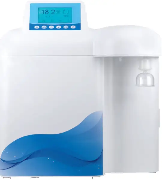
Type I Ultrapure Water Purification System BLPS-204
Laboratory water purification system uses double stage reverse osmosis technology. It produces double stage RO water, Deionised, EDI and ultrapure water. These systems have 3 way on-line water quality sensor, multiple alarm with unique design and it has easy-to-replace cartridges pack unit.
- Integrating with Ionpure Electro deionization technology and module.
- The largest capacity is 240 liters of pure water per day.
- Automatic microcomputer controlling system, multi-menu operating, real-time animation mode display.
- Super-large LCD (Resolution:240x128, dimension:106x57mm) display, display the system running state and various parameters intuitively.
- Up to 3-Year Product Warranty
- US & EU Compliance Standards
- Door-to-Door Shipping
Technical Specifications
Detailed operating and construction parameters for this model.
| Model | BLPS-204 |
| Production Rate | 24L/hr |
| Water Quality | Type I, Type III |
| Feed Water | Tap Water |
| Tank Capacity | 20L |
| Water Inlet | Tap water |
| Temperature | 5-45°C |
| Pressure | 1.0-4.0 Kgf/cm² |
| Bacteria | <0.1 cfu/ml |
| DimensionLxWxH | 545x470x610 mm |
| Weight | 20 kg |
| Power Consumption (W) | 240 W |
| Power Supply | AC110-220 V, 50/60 Hz |
| Note | *The quality of output water accords with the quality of inlet water. |
| Ultrapure Water Quality : | |
| Heavy Metal Ion | <0.1 ppb |
| Endotoxin | <0.001 EU/ml |
| Rnases | <0.01 ng/ml |
| Dnases | <4pg/μl |
| Feed Water Requirements : | |
| Output | 24 L/hrs at 25°C |
| Flow rate (with pressure tank) | >1.5 L/min |
| Resistivity (25°C) | 18.2 MΩ.cm |
| TOC* | 3 ppb |
| Particle (>0.1μm) | <1/ml |
| Conductivity of 2 stage RO water | 1-5μs/cm* |
Product Features
Key design, performance, usability, and safety advantages.
Applications Explore common laboratory, research, industrial, and process applications.
Laboratory, Manufacturing, Reefkeeping, Aquarium, Laboratory, Research
Operating Manual View instructions, operating procedures, safety information, and maintenance guidance.
1. Preface
2. Specification
3. Water Flow Chart
4. Working Environments
5. Installation
5.1 Preparation for installation
5.2 Tube and adapter's connection
5.3 Installation steps
6. Usage Guide
6.1 Starting Up
6.2 Getting Corresponding Pure Water
6.3 Standby
6.4 Shutdown
6.5 Releasing Internal Air Of Terminal Filter
6.6 Flushing UF membrane
6.7 The Usage to Keep High Quality Pure Water
7. Microcomputer Controller
7.1 Panel
7.1 The Specific operation method
7.2 Specification of the main interface
7.3 Specification of main menu
7.4 Specification of alarm
8. Water Quality Test
9. Consumables
10. Normal Trouble Diagnosis
11. Warranty and Repair Regulation.
1. Preface
Dear customer, in the beginning, we sincerely thanks for your choosing our water purification system. This water purification system has incorporated new cuttingedge technology. It is installed and used easily, and can provide you with RO water and ultrapure water for science research. So, it will benefit your work. For the water purification system's maximum efficiency, it is suggested that the user manual should be read before installation. Any question in the installation process, please contact our technology engineers or dealers.
2. Specification
Model | BLPS-104 | BLPS-204 | |
Output -2nd stage RO water* | 12 or 24 liters/hour | ||
Output -ultrapure water | Up to 2 liters/minute (when tank is full) | ||
Ultrapure water quality | |||
Resistivity(25°C) | 18.2MΩ.cm | ||
TOC* | <3ppb | ||
Bacteria | <0.1cfu/ml | ||
Particle(>0.1μm) | <1/ml | ||
Endotoxin | <0.001Eu/ml | ||
RNases | <0.01ng/ml | ||
DNases | <4pg/μl | ||
RO water quality | |||
Conductivity - 1st stage RO water | Feed water conductivityx5%* | ||
Conductivity - 2nd stage RO water | 1-5μs/cm* | ||
Feed water requirements | Tap water, temperature:5-45°C,pressure:1.0- 4.0Kgf/cm2 | ||
Dimension and weight | LengthxWidthxHeight:545x470x610mm / Weight: 25Kg | ||
Electrical requirements | AC220V, 50Hz | ||
Power | 240W | ||
Standard configuration | Main body (Including 1 set of cartridge)+built-in 12 liters pressure tank | ||
Purification System | |||
Sequence number | Specification | Quantity/ set | |
LV.1 | D-pp pretreatment cartridge | 1 |
LV.2 | D-ak Kinetic degradation fluxion cartridge | 1 |
LV.3 | D-ac2 active carbon block cartridge | 1 |
LV.4 | 12 series-150GPD RO membrane | 1 |
24 series-200GPD RO membrane | 1 | |
LV.5 | 12 series-50GPD RO membrane | 1 |
24 series-100GPD RO membrane | 1 | |
LV.6 | D-uvcart (254&185) nm wavelength uv cartridge | 1 |
LV.7 | D-pocart ultrapure polishing resin cartridge | 1 |
LV.8 | D-ufcart eliminating endotoxin uf cartridge | 1 |
LV.9 | D-tefit (0.45+0.1) μm terminal filter | 1 |
Table 1
REMARKS:
*The value will be influenced by temperature and feed water's quality.
3. Water Flow Chart
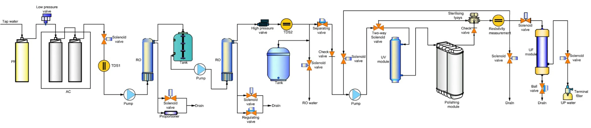
Figure 1
4. Working Environments
• Inlet water: Tap water (TDS<200ppm will be suggested). If inlet water TDS>200ppm, pretreatment is recommended. Water with higher TDS will affect the quality of outlet water and life of purification cartridge.
• Work temperature: 5-45°C
• Pressure: 1.0-4.0Kgf/cm2
• Power: AC220V,50Hz,240W
[Clean, dry working environments would be suggested!]
5. Installation
5.1 Preparation for installation
• The purification system should be installed horizontally and near to tap.
5.2 Tube and adapter's connection
The adapter of the machine is high quality easy-put adapter. And material of tube
is high quality's PE. Tube installation and drag diagram
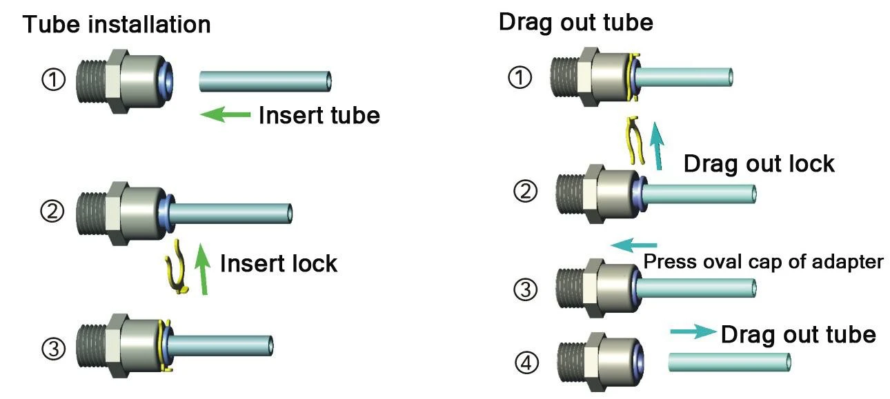
Figure 2
• ATTENTION:
• The tube should be cut with special tube cutter for rounded cut section. And rounded cut section should be guaranteed as much as possible with other cut tools.
• Connect the tube-press the oval cap of the interface strongly, then insert the tube to the bottom of adapter.
• Take off the tube-press the oval cap of the interface strongly, then drag out the tube. Do not drag when the tube can't be dragged out any more.
• The fore-end of the tube, which has been inserted to adapter, should be cut, when it will be used again.
• Sufficient PTFE thread seal tape should be used in all the threaded joints for water leakage inhibitor or preventing.
5.3 Installation steps
(1). Open the packing-case, take out main body, accessory box, water tank (optional).
(2). Take out adapters and tube from accessory box, and read the Instruction Manual carefully.
(3). External interface are on the back of machine, and it is labeled with different color's label. Moreover, its adapters are inserted with different color's stop plug.
• ATTENTION: Stop plug should be pulled out before the following steps.
(4). Connect To Tap Water
There are two ways to connect to the tap. Guide Chart of 2 Ways to Connect To The Tap
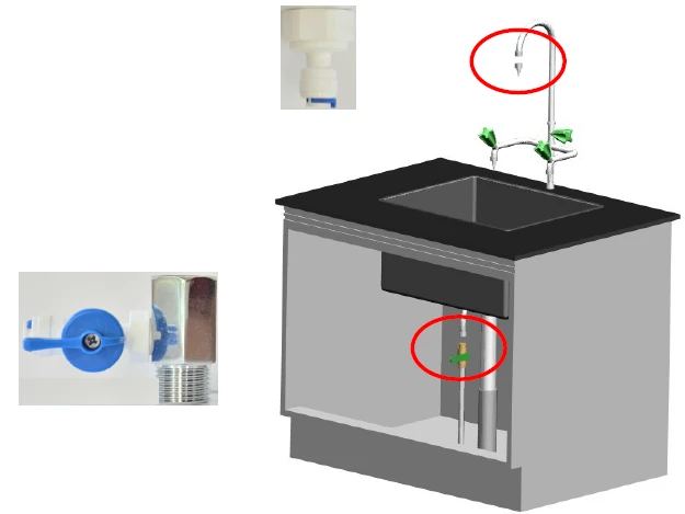
Figure 3
Guide Chart of 2 Ways to Connect To The Tap
 is the place where the interface of machine's inlet water should be
connected.
• 1st way-with tap water adapter 1(1/2″internal thread to 3/8″fast-plug) to connect to tap water.
1. Step: connect tap water adapter 1 to water source Close the valve of the gooseneck. Dismantle the faucet of gooseneck. Screw tap water adapter 1 into the external thread of gooseneck.
2. Step: connect tap water adapter 1 to interface of machine's inlet water Use 3/8" PE tube with a suitable length. Insert one side into the interface of tap water adapter 1, and insert the other into the interface with blue label marked "To inlet water" at the back of machine.
• 2nd way-with tap water adapter 2(tee joint and 3/8″ball valve) to connect to tap water.
1. Step: connect tap water adapter 2 to water source Close the chief valve of tap water. Dismantle the tap. Screw the 3/8'' ball valve with external thread into the side thread with internal thread of tee joint. Screw the tap into the internal thread at one end of the tee joint, and at last, screw the other end with external thread of the tee joint(with 3/8'' ball valve and
the tap at this time) into the internal thread of the tube, where the tap has been connected.
• ATTENTION:
• Sufficient PTFE thread seal tape should be used in all the threaded joints for water leakage inhibitor or preventing
2. Step: connect tap water adapter 2(3/8″ball valve) to interface of machine's inlet water
Use 3/8" PE tube with a suitable length. Insert one side into the interface of 3/8″ball valve, and insert the other into the interface with blue label marked "To inlet water" at the back of machine.
• ATTENTION:
• Extra pretreatment filters (optional) should be connected between the water source and main body.
(5). Connect To RO Wastewater
Use 1/4" PE tube with a suitable length. Insert one side into the interface with black label marked "To drain" at the back of machine, and the other side is directed to drain. (DO NOT JAM!!)
(6). Connect to UF drain
Use 1/4" PE tube with a suitable length. One side connects with the interface with green label marked "To UF drain" at the back of machine, and the other side is directed to drain. Thus the installation is OK. Installation Guide Chart
Ultrapure water outlet: Application: Application:
GC, HPLC, IC, ICP PCR, weather analysis Amino acid analysis Reagent preparation 2nd stage RO water outlet:
Application:
Ware washing, agricultural experiment, general biological experiment, aquatic products feeding , inlet water for ultrapure water machine, inlet water for sterilizer/ t&h chamber
Terminal filter
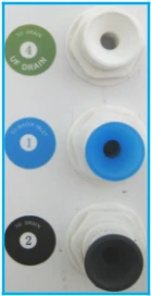
Figure 4
Main body
Spare interface
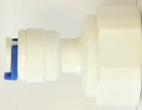
Figure 5
Tap water adapter 1
OR
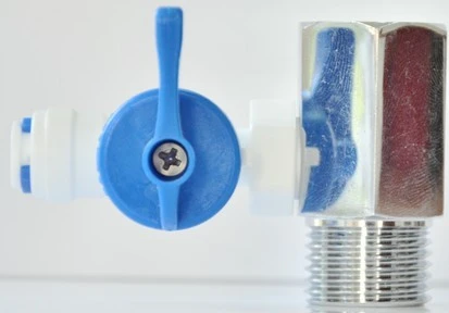
Figure 6
Tap water
Plastic ball valve
Tap water adapter 2-3-direction-links
6. Usage Guide
All data have been set in the factory.
The machine will operate smoothly without any data-setting and debugging. All work state will display on the LCD. If there is abnormal state, the system will alarm automatically. If data modification is necessary, specific step is in "Microcomputer Controller". The power switch is on the side of the shell. Specific picture is as follows
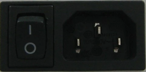
Figure 7
Turn on the power
Turn off the power
6.1 Starting Up
Turn on the tap water valve, insert the power line into the power source and turn on the power switch, then the system begins to produce pure water.
6.2 Getting Corresponding Pure Water
Press"  " or "
 " buttons, which are on the panel, to get corresponding 2nd stage
RO water or ultrapure water(higher quality water than RO water).
6.3 Standby
When 2nd stage RO water and ultrapure water is not for use, the system will be in standby state. The system still produces 2nd stage RO water to store in the interior water tank. Until tank is full, the system will automatically stop. The system will begin to produce pure water again when any pure water is used.
6.4 Shutdown
Turn off the tap water valve and turn off the power switch. Then it is ok.

 ATTENTION: Make sure that the source water and power source is not connected, when the system is not in the use state for long time (for example, off duty).
6.5 Releasing Internal Air Of Terminal Filter
Unscrew the rounded bolt, which is on the side of terminal filter, open the valve of ultrapure water. When ultrapure water goes out, internal air of terminal filter will be released. Until terminal filter is nearly full of pure water, then tighten rounded bolt.
ATTENTION:
If the internal air of terminal filter is not released,pure water can not go through the terminal filter for air's resistance, then the system will stop working for high pressure.
6.6 Flushing UF membrane
▪ Method of flushing UF membrane:
Turn on the UF drain valve (in the right side of case, connecting with UF cartridge), and press "UP" button, which are on the panel, to turn on Ultrapure water's valve.
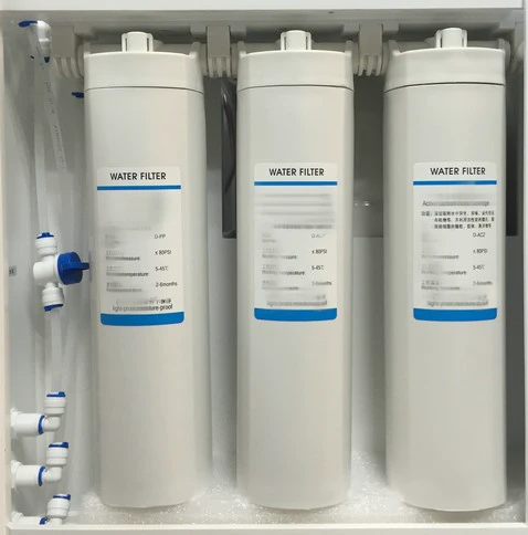
Figure 8
 ATTENTION:
The "UF drain valve" is shut on normal condition, except for flushing UF membrane. Frequency of flushing UF membrane:
At least one times every week, and at least lasting 30 seconds every times.
6.7 The Usage to Keep High Quality Pure Water
(1).The pure water is easily polluted by surrounding environment. So
getting fresh pure water is suggested.
(2).Keep water tank from sunlight for microbes reproducing.
(3).When get high pure water, initial high pure water is suggested to drain
to get steady pure water.
(4).Avoid air bubble when get pure water to reduce air pollution.
The microbe's reproducing will reduce the life of cartridge, when the
machine does not work for long time. So the machine's work every 7-
10days is necessary.
7. Microcomputer Controller
7.1 Panel
There are 6 buttons on the panel

Figure 9
Specification of the buttons:
 Control the solenoid valve of 2nd stage reverse osmosis water
 Control the solenoid valve of ultrapure water
 Main menu, modify all the function and data of the system.
 Shift the cursor to corresponding position
 Adjust the data of chosen position(0-9 circle), or turn on/off
different function
 Confirm the adjusted data and execute corresponding
function.
7.1 The Specific operation method
(1). Choose the menu item, which will be researched or modified.
Press "MENU" button to move the cursor to the menu item. The
chosen item will be allochroic state. Then press "OK" button to enter
corresponding item.
(2). Modify the parameters of menu item or turn on/off the
function of menu item.
Press "MENU" button to choose item, shift button"  " to
 choose the
digit, figure button" " to modify the digital of digit or the turn on/off
the function of menu item when modification is ok, press "OK" button
to confirm.
(3). Return to upper menu or main interface
Press "MENU" button, and move the curs or to return icon  , then
press "OK" button.
7.1.1 Specification at the beginning of working process

Figure 10
(1).When system is power on, the boot screen figure 10 will appear for about 5 seconds.
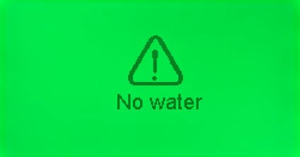
Figure 11
(2). The system will detect the status of feed water after 5 seconds. No feed water or low pressure of feed water, the system will warn Figure 11 .If the status of feed water is
normal, system will implement the following program.
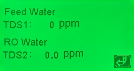
Figure 12
Check TDS and panic value of feed water. Check whether the current TDS of feed water exceeds the previously panic value. If so, system will warn (Figure 12 ) and will not ignore the alarm, until the feed water's quality is normal or pressing "OK" button. Then system switches to the status of flushing RO membrane. If not, system will switch to the status of flushing RO membrane directly.
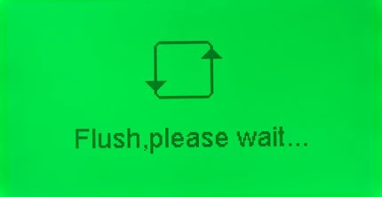
Figure 13
Flushing RO membrane for about 20seconds (Figure 13 ).At the same time system will detect the status of feed water, No feed water or low pressure of feed water, the system will warn
again(Figure 11). When the status of feed water is normal, system will flush the RO membrane again.
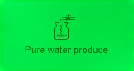
Figure 14
After finishing of flushing RO membrane, system will switch to status of producing pure water (Figure 14). At the same time system will detect the status of feed water, No feed water or
low pressure of feed water, the system will warn again (Figure 11)
2). When the status of feed water is normal, system will continue to produce pure water.
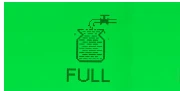
Figure 15
When tank is full, the system will warn (figure 15) And after a few seconds of full tank alarm, system will switch to main interface (Figure 16).
If tank is not full, and system is producing pure water (Figure 14), system also can switch to main interface (Figure 16) through pressing "OK" button. On the status of main interface, system still produces pure water until tank is full, and specific operation can be implemented.
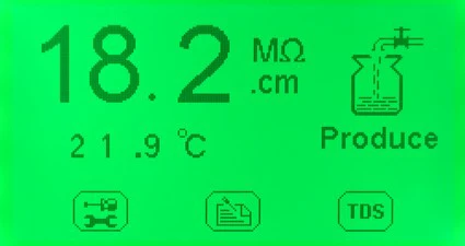
Figure 16
ATTENTION:
Specific operation can be implemented only on the main interface. If system is on the interface of pure water produce (Figure 11 ) or FULL (Figure 14), please just press "OK" button to switch to main interface.
7.2 Specification of the main interface
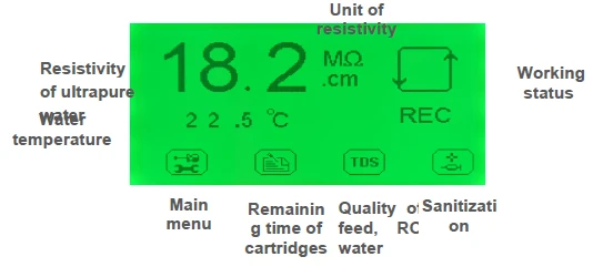
Figure 17
Specification of system's working status icon At the top-right corner of the main interface, system will show 4 kinds of working status-REC, Produce, FULL, No water. It respectively means: Recirculation of ultrapure water, Producing RO water, tank is full of water, no feed water or low pressure of feed water.
Definite icons are as follows:
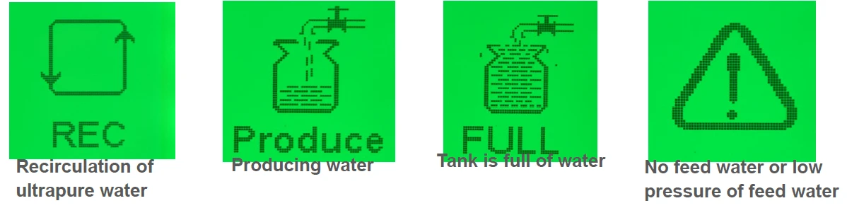
Figure 18
(2). Specification of cartridges' remaining time icon
Under the main interface, press "MENU" but  but move the cursor to icon
, then press "OK" button to switch to interface Cartridges' remaining time (Figure 18).
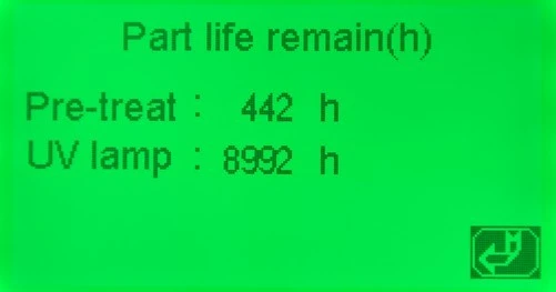
Figure 19
• Specification of the interface
"Pre-treat: 442h": It means that the PP spun fiber filter's remaining time is 442 hours (Initial value is 450 hours);
"UV lamp: 8992h": It means that the UV lamp's remaining time is 8892 hours (Initial value is 9000 hours ).
REMARKS:
UV lamp is optional. If there is no UV cartridge in the system, "UV lamp: 8992h" will not show.
(3). Specification of feed water and RO water's quality icon
Under the main interface, press "MENU" button  Move the cursor to icon
, then press "OK" button to switch to interfac eed water and RO water's quality (Figure 20).
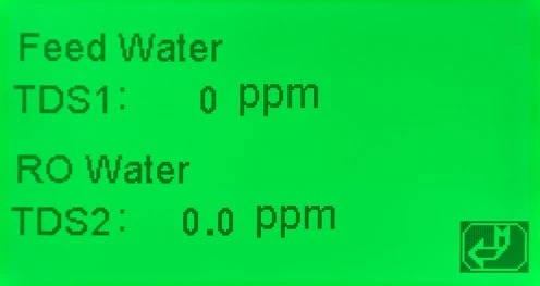
Figure 20
Specification of the interface
"Feed water": It represents the source water or tap water;
"TDS1: 0ppm": It means that the value of feed water's TDS is 0, the unit is ppm (mg/l);
"RO water": It represents reverse osmosis water;
"TDS2: 0.0ppm": It means that the value of RO water's TDS is 0.0, the unit is ppm (mg/l).
Specification of sanitization icon
Under the main interface, press "MENU" button,  move the cursor to icon
, then press "OK" button to switch to interface of sanitization(Figure 21). (Under the main interface, interface of sanitization also can be switched to, through pressing "OK" button 3 times continuously)
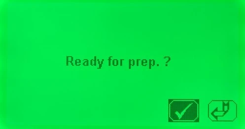
Figure 21
At this time, machine would stop working, and prepares for sanitization.
Method of sanitization
At first, open top cap of disinfection box, then put 1 piece of disinfecting tablet inside, tigh then cap again. Lastly press "MENU" button, move the cursor to icon  , press "OK" button to start sanitization procedure (Figure 22).

Figure 22
Sanitization process will persist for 3-4 hours. During this time, the solenoid valve of pure water outlet will be closed and all the buttons in panel will not be operated.
ATTENTION:
Shutting off the power and restart are prohibited in sanitization process. Otherwise disinfecting tablet water will enter into pure water cartridge, the service life of cartridge will reduce greatly.
(5). Specification of main menu icon
Under the main interface, press "MENU"  bu ove the cursor to icon
, then press "OK" button to switch to interface of password entry (Figure 23)
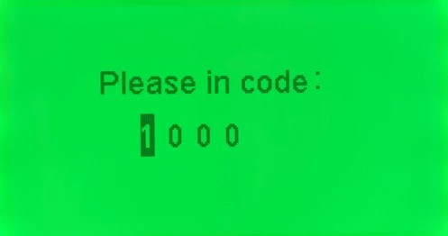
Figure 23
The initial code is "1000".
Inputting initial code"1000" through shift button and figure button, then press "OK" button to confirm
If code is wrong, system will warn and return to main interface.
If code is right, system will switch to interface of main menu (Figure 24). Under the main menu, press "MENU" button, move the cursor to corresponding icon, then press "OK" button to switch to the corresponding menu item.
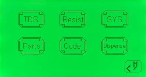
Figure 24
7.3 Specification of main menu
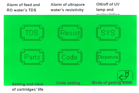
Figure 25
(1). Specification of icon- alarm of feed and RO water's TDS
Under the main menu, press "MENU"  button, move the cursor to icon
, then press "OK" button to switch to interface of feed and RO water
quality's standard-exceeding alarm setting (Figure 26).
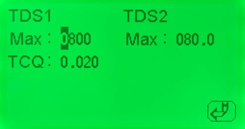
Figure 26
◦ Specification of the interface
• "TDS1": It represents TDS of source water or tap water.
◦ "Max: 0800": It means when the TDS value of TDS1 exceeds 800 ppm(initial setting value), the system will warn and display the interface of feed water quality's standard-exceeding alarm (Figure 27).
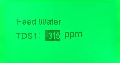
Figure 27
• "TDS2": It represents TDS of RO water.
◦ "Max: 080.0": It means when the TDS value of TDS2 exceeds 80 ppm(initial setting value), the system will warn and display the interface of RO water quality's standard-exceeding alarm (Figure 28)
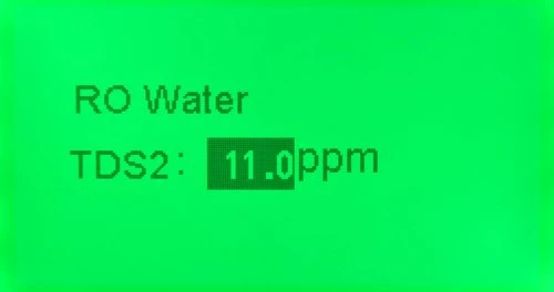
Figure 28
"TCQ: 0.020": It represents that temperature compensation coefficient is 0.020(initial setting value, any modification is prohibited).
▪ REMARKS:
TDS1-feed water quality's standard-exceeding alarm is effective only when the machine just start.
The value of TDS1 which system display is definite feed water's quality (Figure 29).
When the TDS value of actual feed water's quality < Max(setting value),system will cancel the alarm.
◦ The purpose of feed and RO water quality's standard-exceeding alarm
• The purpose of TDS1's alarm(feed water quality's standard-exceeding alarm):Remind that the feed water's quality is bad, and the extra pretreatment is necessary to protect the cartridges of main body.
• The purpose of TDS2's alarm(RO water quality's standard-exceeding alarm):Remind that RO water's quality is bad, and RO membrane should be replaced to protect the post cartridges.
Setting method of feed and RO water quality's standard-
exceeding value
The TDS value of feed and RO water quality's standard-exceeding alarm can be modified according to the local feed water's quality in the course of machine.
• General principles of alarm value setting
TDS1's Max value: Slightly larger than the actual measured value; TDS2's Max value: ≤TDS1's Max valuex10%. Because the desalinization ratio of new RO membrane is above 95%.( TDS2's Max value ≤TDS1's Max valuex5%)
• The method of alarm value setting
In the interface of feed and RO water quality's standard-exceeding alarm setting (Figure 29 ),press "MENU" button, move the cursor to corresponding item, reset it through shift and figure button, at last press "OK" button to confirm.
(2). Specification of icon- alarm of ultrapure water's resistivity
Under the main menu, press "MENU" button over the cursor to icon
, then press "OK" button to switch to interface of ultrapure water resistivity's standard-exceeding alarm setting (Figure 29).
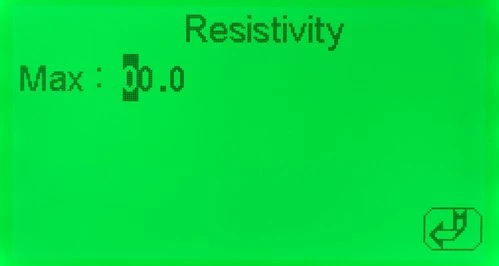
Figure 29
Specification of the interface
• "Max: 00.0": When the actual resistivity of ultrapure water is less than 0 MΩ.cm (initial setting value), the machine will warn to remind ultrapure water resistivity's standard-exceeding. And system will display interface of ultrapure polishing resin cartridge replacement's reminding (Figure 30).
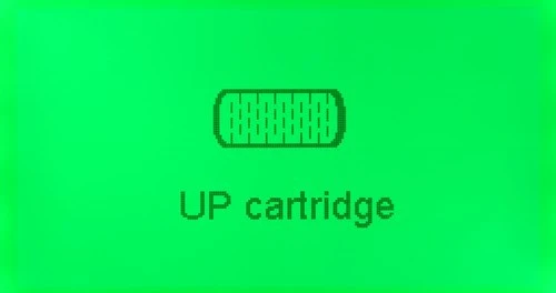
Figure 30
 REMARKS:
When the resistivity of ultrapure water exceeds the standard setting value, the system will warn 1 times every 10 seconds. During this time, the solenoid valve of pure water outlet will be closed. If opening solenoid is necessary, the value of ultrapure water resistivity's standard-exceeding must be reset. The purpose of ultrapure water resistivity's standard-exceeding alarm Remind that the actual value of resistivity is lower than the setting value. Maybe the quality of ultrapure is not suitable for the experiment. Replacing the ultrapure polishing resin cartridge is necessary. Setting method of ultrapure water resistivity's standard-exceeding value The resistivity's value of ultrapure water resistivity's standard-exceeding can be reset according to actual requirement for ultrapure water.
• General principles of alarm value setting According to actual requirement for ultrapure water
• The method of alarm value setting
In the interface of ultrapure water resistivity's standard-exceeding
alarm setting (Figure 29), press "MENU" button, move the cursor to corresponding item, reset it through shift and figure button, at last press "OK" button to confirm.
(3). Specification of icon- ON/OFF of UV lamp and recirculation
Under the main menu, press "MENU" button,  move the cursor to icon
, then press "OK" button to switch to interface of UV lamp and recirculation ON/OFF (Figure 31).
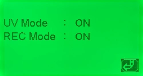
Figure 31
• Specification of the interface
◦ "UV Mode: ON": It means that the monitoring function of UV lamp is turned on. (OFF means turning off)
◦ "REC Mode: ON": It means that the recirculation function is turned on. (OFF means turning off)
 REMARKS:
UV lamp is optional. Some models have no UV lamp cartridge, if so, UV Mode's initial setting is OFF. Otherwise, it is ON.
Recirculation function is optional. Some models have no this function, if so, REC Mode's initial setting is OFF. Otherwise, it is ON.
• The purpose of UV lamp and recirculation ON/OFF
◦ UV lamp alarm: means that life of UV lamp is over, replacement of UV lamp is necessary.
◦ Recirculation ON/OFF: system can restrain bacteria's increase and keep high quality's ultrapure water.
• Setting method of UV lamp and recirculation ON/OFF:
In the interface of UV lamp and recirculation ON/OFF (Picture31), press "MENU" button, move the cursor to corresponding item, reset it through shift and figure button, at last press "OK" button to confirm.
Figure 32
(5). Specification of icon- setting and clear of cartridges' life
Under the main menu, press "MENU" button  move the cursor to icon
, then press "OK" button to switch to interface of setting and clear of cartridges' life (Figure 32).
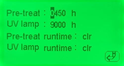
Figure 33
Specification of the interface
• "Pre-treat: 0450h": It means that the PP spun fiber filter's initial setting time is 450 hours. When its runtime exceeds 450 hours, the system will warn and display the interface of pretreatment cartridge replacement's reminding (Figure 33).
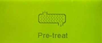
Figure 34
"UV lamp: 9000h": It means that the UV lamp's initial setting time is 9000 hours. When its runtime exceeds 9000 hours, the system will warn and display the interface of UV lamp replacement's reminding (Figure 34).

Figure 35
• "Pre-treat runtime: clr": clear the runtime of pretreatment cartridges to zero, system will reset timer.
• "UV lamp runtime: clr": clear the runtime of UV lamp to zero, system will reset timer.
REMARKS:
The above 2 operation are implemented generally on the condition of replacing cartridges.
UV lamp is optional. If there is no this part, "UV lamp: 9000h", "UV lamp runtime: clr" and "Figure 35" will not display.
The basis for pretreatment cartridge's life-450 hours is the runtime of system-5 hours every day,30 days every month,3 months.
The basis for UV lamp's life-9000 hours is the runtime of system-24 hours every day with Uninterruptible power supply. If the lamp is turned on and off frequently, its life will reduce strikingly.
Setting method of setting and clear of cartridges' life
• The principle of setting of cartridges' life:
according to the actual replacement term.
• Method of setting cartridges' life: In the interface (Figure 33), press "MENU" button, move the cursor to corresponding item, reset it through shift and figure button, at last press "OK" button to confirm.
• Method of clear of cartridges' life: In the interface (Figure 33), press "MENU" button, move the cursor to "clr" item, then press "OK" button to confirm.
 ATTENTION:
Clearing cartridges' life must be implemented once replacing new cartridge is ok.
(6). Specification of icon- code setting
Under the main menu, press "MENU"  button, move the cursor to icon
, then press "OK" button to switch to interface of code setting (Figure 36).
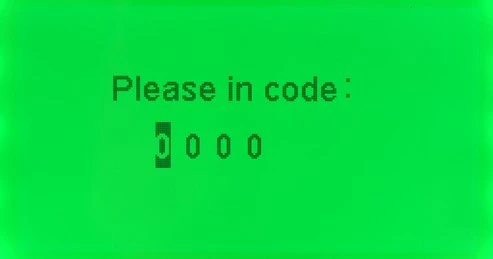
Figure 36
Specification of the interface
"0000": It means that the password is "0000".
ATTENTION: Initial setting password is "1000")
Method of code setting
For enhancing management of the machine,If needed,password can be reset to protect system's parameter from modification.
• Specific method: In the interface (Figure 36), move the cursor to corresponding item, through shift button to choosing the digit and figure button to modifying the digital of digit, at last press "OK" button to confirm. From now on, the initial setting password "1000" is invalid.
ATTENTION:
Once new code setting is ok, please make sure to input new password in interface of password entry (Figure 23 ).
If new password is forgotten,please no hesitate to contact with our company.
Specification of icon- Mode of getting water
Under the main menu, press "MENU" button  Move the cursor to icon
, then press "OK" button to switch to interface of getting water's mode (Figure 37).
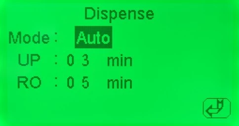
Figure 37
Specification of the interface:
• "Mode: Manual": It means that the current mode of getting water is manual.
Specification of manual mode:
Under this mode, press the dispense button first times,then the solenoid valve of pure water is opened. Press the dispense button again,then the valve is closed. )
• "Mode: Auto": It means that the current mode of getting water is automatic.
Specification of auto mode:
Under this mode, press the dispense button,then the solenoid valve of pure water is opened. And the valve will be automatically closed after the setting time.
 ATTENTION: Initial setting mode of getting water is Manual.
"UP: 03min": It means that the getting ultrapure water's time of auto mode is 3 minutes.
"RO: 05min": It means that the getting RO water's time of auto mode is 5 minutes.
 REMARKS:
Time setting is effective only under auto mode;
Time frame: 1 minute to 99 minutes.
Setting method of getting water's mode:
In the interface (Figure 37), press "MENU" button, move the cursor to
corresponding item, through shift button to choosing the digit and figure button to modifying the digital of digit, at last press "OK" button to confirm.
7.4 Specification of alarm
(1). Alarm of no feed water or low pressure of feed water
System continuously monitors the pressure of feed water. If no feed water or low pressure of feed water, system will warn (Figure 11).
• The alarm of starting up and flushing RO membrane:
Display warning Figure 11, accompanied by buzzer alarm. System will continue to flush RO membrane until the pressure is ok.
• The alarm in the process of producing pure water:
Display warning Figure 11, accompanied by buzzer alarm. System will continue to produce pure water until the pressure is ok.
• The alarm in other work status:
Display warning Figure 11, accompanied by buzzer alarm. Warning time will sustain 3 seconds. System will work again after 3 seconds. System will monitor the pressure again every 1minutes.
(2). Alarm of cartridges' life
Including: pretreatment cartridge replacement's reminding (Figure 34), UV lamp replacement's reminding (Figure 35), ultrapure polishing resin cartridge replacement's reminding (Figure 32).
• Alarm of pretreatment cartridge replacement's reminding
(Figure 34), and UV lamp replacement's reminding (Figure 35).
When the runtime is above the initial setting value of cartridges' life, system will warn, and display warning picture 2, accompanied by buzzer alarm. Warning time will sustain 3 seconds, and system will monitor the pressure again every 1 hour. It means that system will warn 1 times every hour until the initial setting value is modified or the runtime is cleared to zero.
• Alarm of ultrapure polishing resin cartridge replacement's reminding (Figure 32 ).
When system's real time resistivity is less than the initial setting value, system will warn, and display warning Figure 32 , accompanied by buzzer alarm. Warning will occur every 10 seconds. The solenoid valve of pure water's outlet will not be opened when system is warning. If opening is necessary, please modify the initial setting value of resistivity's alarm.
8. Water Quality Test
The system has 3 monitor sensors of water quality measuring.
◦ The first, TDS1, monitors feed water's quality (tap water, inlet water). Measure unit: TDS(total dissolved solid, ppm)
◦ The second, TDS2, monitors 2nd stage reverse osmosis water's quality(2nd stage RO water).
Measure unit: TDS(total dissolved solid, ppm)
◦ The third, Resist, monitors ultrapure water's quality (Ultrapure water). Measure unit: Resistivity (MΩ.cm)
REMARKS:
◦ Under normal conditions, new RO membrane's desalination rate is above 95%. It means that TDS of RO water should be less than TDS of inlet tap waterx5%.
◦ If TDS of RO water > TDS of inlet tap waterx10%, it means that RO membrane's desalination can't meet the minimum requirements. RO membrane should be replaced at once.
◦ Conversion relations between TDS and conductivity rate(μs/cm): If TDS<50ppm, conductivity rate (μs/cm) ≈TDSx2
If TDS>200ppm, conductivity rate (μs/cm) ≈TDSx(1.5~1.7).
9. Consumables
Item No. | Specification | Suggested replacement term |
D-PP | Pretreatment cartridge | About 2-6 months |
D-AK | cartridge | About 12 months |
D-AC2 | Active carbon block cartridge | About 4-6 months |
D-RO-200 | Reverse osmosis membrane | About 12-24months |
D-RO-150 | Reverse osmosis membrane | About 12-24months |
D-RO-100 | Reverse osmosis membrane | About 12-24months |
D-RO-50 | Reverse osmosis membrane | About 12-24months |
D-Uvlamp | D-uvlamp (254&185) nm wavelength uv lamp | About 9000 hours |
D-Pocart | Ultrapure polishing resin cartridge | About 4500 liters pure water |
D-Ufcart | D-ufcart eliminating endotoxin uf cartridge | -- |
D-Tefit | (0.45+0.1) μm terminal filter | -- |
Table 2
10. Normal Trouble Diagnosis
Normal trouble | Cause | Diagnosis |
No power | -No plug in -Power adapter broken | -Check the power connecting -Replace new adapter |
No pure water goes out or a little amount of pure water | -Valve of pure water outlet broken -Pump broken -Cartridges or filters' life ends | -Replace new valve -Replace new pump -Replace new cartridges or filters |
Cartridges' life warns | -Cartridges' life ends | -Replace new cartridges |
Water leakage | -Adapter or something broken | -Check, insert and drag out again, replace |
Water quality deteriorate | -Cartridges or filters' life ends -Water quality sensor | -Replace new cartridges or filters -Replace new water quality |
Table 3
11. Warranty and Repair Regulation.
The products enjoy repair service since the day of purchase. In one year from the purchasing day, we are obliged to replace components for customers free of charge, due to non-human-behavior factors, except for:
(1). All the consumables;
(2). Damage caused by maloperation or use in abnormal situations;
(3). Disassembly any part of the machine or human-behavior damage;
(4). Not repaired by our serviceman.
Specification can be changed without any prior notice for development.