Get Price
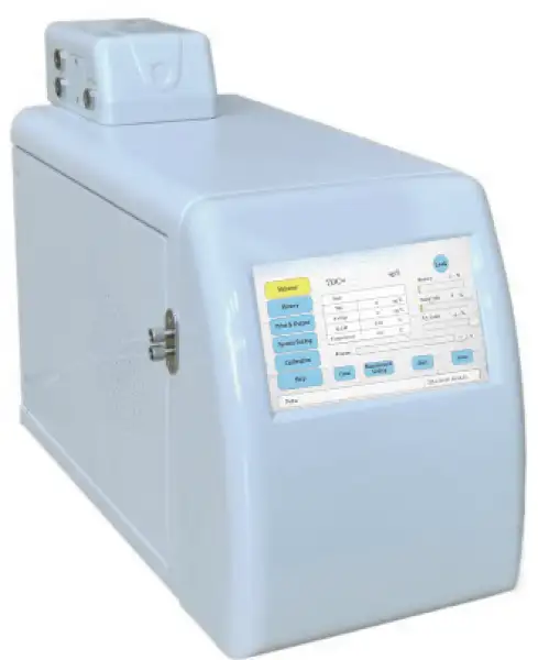
TOC Analyzer BANA-602
- • Ideal choice to measure Microelectronics Water, Purified Water, Ultra Pure Water and Water For Injection, etc.
- • Smart 7 inches touch screen with user-friendly UI, easy to operate and read data.
- • UV Oxidation by UV Lamp, no need to add acid, gas or catalyst, greatly reduced experiment cost.
- • Equipped with a sensitive conductivity detector to quantify TOC concentration accurately.
- • Online mode to realize real-time monitoring .
- • One button sampling, less sample contamination, no harm on operator and environment.
- • Optional PC software, comply with FDA 21 CFR Part 11 requirements and USP, EP, ChP and JP.
- • Optional 20-position autosampler.
- Up to 3-Year Product Warranty
- US & EU Compliance Standards
- Door-to-Door Shipping
Technical Specifications
Detailed operating and construction parameters for this model.
| Model | BANA-602 |
| Measurement Range | 1-1500 ppb |
| Detection Limit | 1 ppb |
| Max Tolerance | ±5% |
| Analysis Time | 3 min |
| Response Time | within 10 min |
| Sample Flow Speed | 2 mL/min |
| Repeatability Tolerance | ≤ 3% |
| Power Requirement | AC110/220V, 50/60Hz, 100W |
Product Features
Key design, performance, usability, and safety advantages.
Operating Manual View instructions, operating procedures, safety information, and maintenance guidance.
1. Preface
2. Important Information
3. Warranty
4. Safety Instructions
5. Overview
5.1 Product Introduction
5.2 Performance Features
5.3 Measurement Principle
5.4 Applications
6. Technical Specifications
6.1 Technical Parameters
6.2 Measuring Principle Diagram
7. Hardware Components
7.1 Front View
7.2 Left View
7.3 Right View
7.4 Rear View
7.5 Top View
7.6 Internal Left View
8. Installation and Preparation for Testing
8.1 Installation Requirements
8.2 Preparation for Analysis
9. Instrument Installation
9.1 Online Module Installation
10. Instrument Operation
10.1 Software Operation
10.2 Standalone Operation
1. Preface
Please read this manual carefully before using this product. Thank you for purchasing this product.
This operation manual is the user manual for the TOC Conductivity Meter Instruction, which explains the standalone operation, software operation, data management, maintenance, and repair methods of the TOC Conductivity Meter Instruction. It is suitable for users with a basic knowledge of chemistry. Please read this manual carefully before operation and use the product correctly.
Please keep this manual for future reference.
2. Important Information
1. If there is a change in the user or usage location, please hand over this manual to the subsequent user.
2. If this manual or the warning labels on the product are lost or damaged, please contact our company immediately.
3. To ensure safe operation, please read the "Safety Instructions" carefully before using this product.
4. After unpacking, please check if the provided parts model and quantity are correct. If they are incorrect, please contact our company immediately.
5. To ensure safe operation, please entrust our company with the installation, commissioning, or reinstallation of the instrument after moving.
6. If the instrument has not been used for a long time, confirm that the sample pump, UV lamp, etc., are working properly after powering on.
3. Warranty
Warranty Period: The warranty period is determined according to the terms of the contract signed with our company.
Warranty Coverage: If any malfunction occurs due to manufacturing defects, the manufacturer will provide free repair or replacement of parts within the warranty period.
The warranty does not cover the following:
(1) Improper operation.
(2) Unauthorized unpacking or failure to follow the unpacking instructions, resulting in damage or loss of parts.
(3) Repairs or modifications performed by anyone other than our company or companies designated by us.
(4) Use with hardware or software not specified by our company.
(5) Failures caused by computer viruses, and damage to software and data, including basic software.
(6) Failures and damage to software and data, including basic software, caused by power outages or sudden voltage drops.
(7) Failures and damage to software and data, including basic software, caused by improper shutdown.
(8) Failures not caused by the product itself.
(9) Failures caused by the use of the product in harsh environments such as high temperature, high humidity, corrosive gases, or vibrations.
(10) Failures caused by uncontrollable accidents such as fire, earthquake, other natural disasters, radioactive material and hazardous substance contamination, and war riots and crimes.
(11) Failures caused during self-movement or transportation of the product after installation.
(12) Consumables or parts equivalent to consumables.
4. Safety Instructions
Installation Location Precautions
The TOC Conductivity Meter Instruction weighs 13 kg. Consider the total weight when used in conjunction with a computer and auto sampler during installation. The lab bench used for installing this instrument should be sturdy enough to support the total system weight. The bench should be level, stable, and at least 600 mm deep, otherwise, the instrument may tip over or fall off the bench.
Installation Precautions
1. Take measures to prevent the instrument from falling during an earthquake or other disasters, as strong vibrations may cause the instrument to fall and get damaged.
2. This instrument can only be connected to a power source with the specified voltage; otherwise, it may cause fire or electric shock. Check if the power voltage is stable and the current capacity is sufficient for all system components. Otherwise, the instrument cannot work at its rated performance.
3. The instrument should be grounded to prevent electric shock caused by accidents or electric leakage. Grounding is also important for the stable operation of the instrument.
4. Do not place heavy objects on the power cable, keep the power cable away from any heat sources, and do not modify, excessively bend, or stretch the power cable, as this may damage the power cable and cause fire, electric shock, or malfunction. If the power cable is damaged, contact our company's after-sales engineer immediately.
Operational Precautions
1. Always wear protective gloves and goggles when handling solvents and samples. Solvent splashes in the eyes may cause blindness. If solvent splashes into the eyes, rinse immediately with plenty of water and seek medical attention.
2. Do not use flammable sprays (such as hair spray, insecticide, etc.) near the instrument, as they can ignite and cause fire.
Instrument Inspection, Maintenance, Adjustment, and Care Precautions:
1. Before inspecting, maintaining, or replacing parts, turn off the power to prevent electric shock or short-circuit accidents.
2. If there is dust on the power plug, unplug it from the power outlet and wipe off the dust with a dry cloth. Accumulated dust can cause fire.
3. If water enters the instrument, dry it immediately to prevent rusting. Do not use alcohol or other solvents to clean the instrument as they can cause discoloration of the instrument surface.
4. Dispose of waste liquids properly according to the instructions of the management department.
5. Overview
5.1 Product Introduction
The TOC Conductivity Meter Instruction series Total Organic Carbon (TOC) Analyzer is a high-performance, high-reliability conductivity TOC analyzer independently developed and manufactured by our company. The TOC Conductivity Meter Instruction can detect TOC
concentrations in water samples ranging from 1μg/L to 1500μg/L. This product is easy to operate, has low maintenance costs, and requires no chemical reagents.
This product complies with GMP requirements for computerized system validation and meets FDA 21 CFR PART 11 requirements for electronic data integrity, electronic signatures, and audit trails.
5.2 Performance Features
(1) Utilizes UV photolytic oxidation without the need for catalysts and carrier gases.
(2) Equipped with a buzzer alarm function that activates when the set upper limit is exceeded, protecting the instrument and preventing operational errors.
(3) Requires no additional acid reagents, oxidizers, or any gases, thus incurring no extra daily maintenance costs.
(4) Designed specifically for detecting TOC content in deionized water with concentrations below 1000μg/L.
(5) Built-in large-capacity memory with a standard capacity of 8GB, with no storage time limitations.
(6) Fast detection speed, with each detection taking no more than 3 minutes.
(7) Compact size, lightweight, low energy consumption, and portable.
(8) Features a 7-inch color touch screen with a user-friendly interface.
(9) Allows historical records to be queried by detection date, with clear and detailed historical files and data.
(10) Includes a USB data copy function, allowing all data within a day to be copied based on the date, facilitating data export and backup.
(11) Supports Bluetooth printing, equipped with a compact Bluetooth printer for easy and fast printing.
(12) Complies with GMP requirements for computerized system validation and meets FDA 21 CFR PART 11 requirements for electronic data integrity, electronic signatures, and audit trails.
5.3 Measurement Principle
The organic compounds in the sample are oxidized into carbon dioxide under the influence of ultraviolet (UV) light, and the carbon dioxide is measured using conductivity detection technology. The total organic carbon (TOC) concentration is calculated by measuring the total inorganic carbon (TIC) concentration of the unoxidized sample and the total carbon (TC) concentration of the sample after oxidation. The TOC concentration is the difference between the total carbon concentration and the total inorganic carbon concentration:TOC = TC - TIC.
UV Lamp Oxidation Principle: The UV lamp emits light at wavelengths of 185 nm and 254 nm, which causes photodecomposition of water.
H₂O + hv 185nm → OH. + H.
The hydroxyl radical (OH˙) can completely oxidize organic compounds into carbon dioxide.
Organic compounds + OH. →CO₂ + H₂O
5.4 Applications
The conductivity TOC analyzer can be used to test the organic carbon content in pure water, deionized water, and water for injection in the pharmaceutical industry. It is used for ultra-pure water TOC detection in the semiconductor industry, power plants, research institutions, laboratories, and more. In the pharmaceutical and biochemical fields, it can be used for cleaning validation to verify cleaning effectiveness. It can also be used for online monitoring of water production systems in the pharmaceutical industry, ultra-pure water preparation systems in the semiconductor industry, wafer process technology, and the deionized water preparation process in power plants.
6. Technical Specifications
6.1 Technical Parameters
Power Supply | (220±22)V,(50±1)Hz |
Operation Mode | Computer control, Standalone operation |
Application | Liquid |
Measurement Principle | UV Oxidation |
Rated Power (W) | 100 |
Ambient Temperature | 5°C - 35°C,temperature variation within ±5°C/day |
Relative Humidity | ≤85 % |
Detection Range | 1-1500μg/L |
Analysis Time | 1min |
Total Organic Carbon Indication Error | ±5 % |
Total Organic Carbon Measurement Repeatability | ≤3 % |
Dimensions | 440*220*366mm(Depth*Width*Height) |
Weight | 13kg |
Table 1
6.2 Measuring Principle Diagram
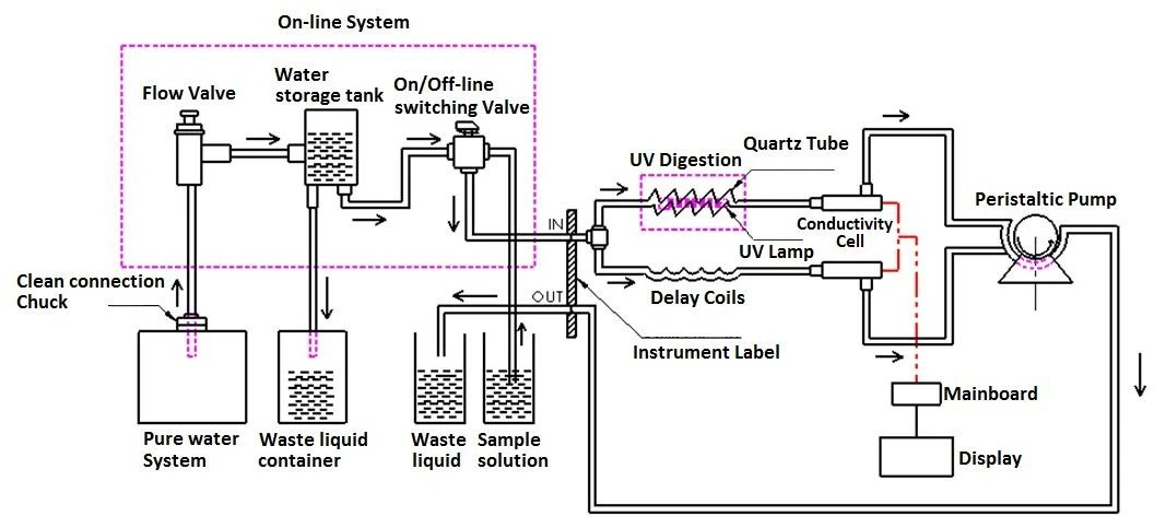
Figure 1
7. Hardware Components
7.1 Front View
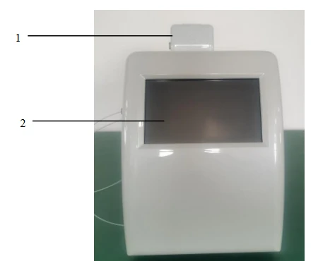
Figure 2
1. Online Module
2. Operation Screen
7.2 Left View
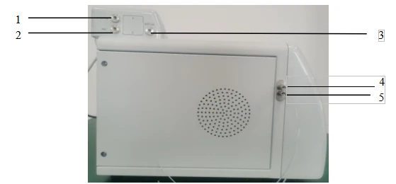
Figure 3
1. Online Sample Inlet
2. Main Unit Sample Inlet
3. Offline Sample Inlet
4. Sample Inlet
5. Waste Outlet
7.3 Right View
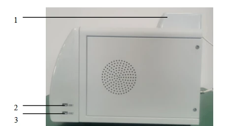
Figure 4
1. Online Module
2. USB Port
3. USB Interface
7.4 Rear View
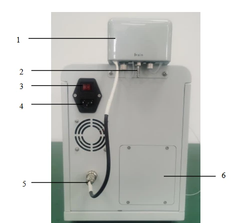
Figure 5
1. Online Module
2. Drainage Pipe Interface
3. Power Switch
4. Power Interface
5. Online Aviation Socket
6. UV Lamp Cover
7.5 Top View
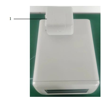
Figure 7
1. Online Module
7.6 Internal Left View
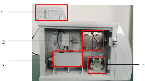
Figure 8
1. Online Module
2. Conductivity Cell
3. UV Lamp Box
4. Peristaltic Pump
8. Installation and Preparation for Testing
8.1 Installation Requirements
8.1.1 Power Requirements
The instrument must have a good grounding line, and the power socket must be a three-pronged socket with good grounding.
Please connect to a stable power source of AC (220±22) V, 50/60 Hz, single-phase with a capacity of 10A or more. If the power voltage exceeds this range, it may severely damage the instrument.
8.1.2 Space Requirements
(1) Laboratory bench dimensions: length: ≥ 200cm, width: ≥ 70cm, height: 70cm-80cm. The bench surface should support at least 100kg, be stable without vibration, and be resistant to heat and acids.
(2) The distance between the back of the instrument and the power socket should be ≤ 150cm for easy connection to the power supply.
8.1.3 Environmental Requirements
(1) Do not install the instrument near windows or doors to avoid drafts, dust, corrosive gases, and vibrations.
(2) Keep away from strong electromagnetic field interference.
(3) Avoid fire hazard areas; some internal components may reach high temperatures and could cause a fire.
(4) Environmental temperature: 5-35°C.
(5) Working humidity: 10-80% RH.
8.1.4 Computer Requirements
(1) Hardware Configuration: CPU: 3GHz or above, Memory: 4G or above, Hard Disk: 500GBor above (at least divided into two partitions).
(2) External Interface: USB 2.0 or higher
(3) Operating System: Windows 10 Pro or Enterprise edition.
(4) Pre-installed Software: PDF reader with PDF printing capabilities.
(5) Monitor: Resolution 1600*900.
8.1.5 Reagent Requirements
No. | Name | Specifications |
1 | Pure Water | TOC less than 100μg/L, conductivity less than 1uS/cm (25°C) |
2 | Sucrose | Standard reagent or superior grade |
3 | 1,4-Benzoquinone | Standard reagent or reference substance |
Table 2
8.2 Preparation for Analysis
8.2.1 Solution Preparation
1. Zero Calibration Water
Zero calibration water must use high-purity water containing less than 100μg/L total organic carbon and less than 1uS/cm conductivity (25°C).
Note:
It should be used immediately after preparation, and should not be stored in open beakers or containers. Exposure to air for over an hour can alter the TOC value due to dissolved carbon dioxide.
2. Sucrose Solution (ρTOC=100mg/L)
Accurately weigh 0.2377g of dried, high-purity sucrose and dissolve it in pure water. Transfer to a 1000mL volumetric flask and dilute to the mark with pure water, then mix well. This is the standard stock solution, which can be further diluted to prepare other concentrations as needed.
Note:
Before preparing the standard solution, the sucrose standard must be dried at 105°C (221F) to constant weight.
3. 1,4-Benzoquinone Solution (ρTOC=100mg/L)
Accurately weigh 0.1501g of analytical grade 1,4-benzoquinone and dissolve it in pure water. Transfer to a 1000mL volumetric flask and dilute to the mark with pure water, then mix well. This is the standard stock solution, which can be further diluted to prepare other concentrations as needed.
8.2.2 Calibration Solution Preparation
From the sucrose standard stock solution (ρTOC=100mg/L), prepare calibration solutions of 200μg/L, 500μg/L, and 1000μg/L by stepwise dilution. Use zero calibration water for dilution.
8.2.3 System Suitability Solution Preparation
1. Sucrose Reference Solution (ρTOC=500μg/L)
Prepare a 500μg/L sucrose reference solution by stepwise dilution from the sucrose standard stock solution (ρTOC=100mg/L). Use zero calibration water for dilution.
2. 1,4-Benzoquinone Reference Solution (ρTOC=500μg/L)
Prepare a 500μg/L 1,4-benzoquinone reference solution by stepwise dilution from the
1,4-benzoquinone standard stock solution (ρTOC=100mg/L). Use zero calibration water for dilution.
9. Instrument Installation
9.1 Online Module Installation
Align the online module with the two holes on the back of the instrument and secure it with two mounting screws.
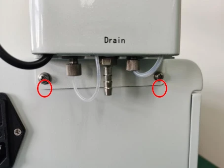
Figure 9
Connect the aviation plug on the online module to the main unit.
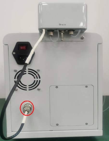
Figure 10
Unscrew the stainless steel fitting at the sample inlet on the main unit. Take the 40cm online sample tube from the accessories, connect one end to the sample inlet on the main unit and the other end to the main unit sample inlet on the online module.
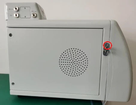
Figure 11
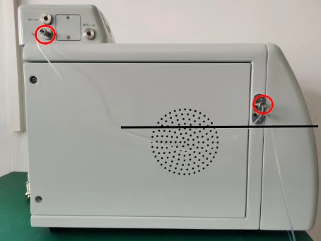
Figure 12 (40cm Sample Tube)
Take out the other 300cm online sample tube. Connect one end to the online sample inlet on the online module (Figure 5.5), and the other end to the dedicated online tubing interface. At the same time, connect the Waste liquid drain tube to the drainage pipe interface.
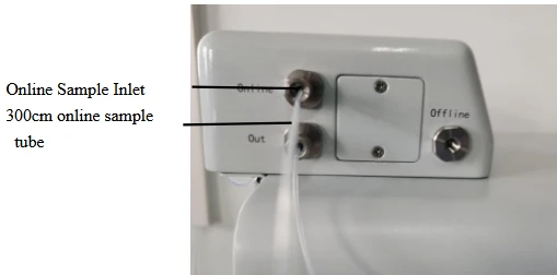
Figure 13
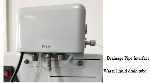
Figure 14
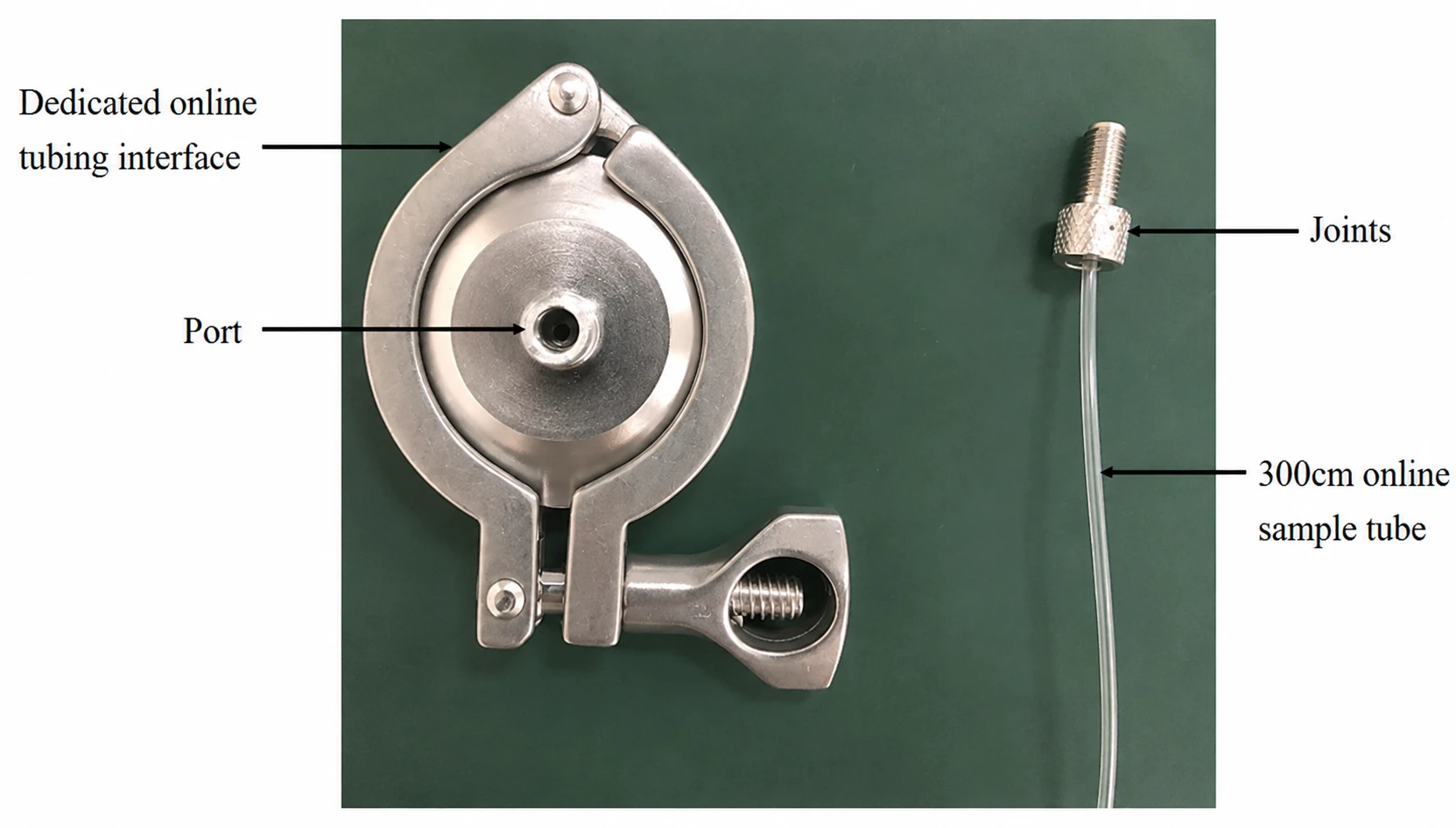
Figure 15
Note:
The online sampling tube of the online detection device should be connected to the water supply tubing of the water purification equipment using the dedicated online tubing interface, which is a standard accessory as shown in (the right side shows the connector). The outer diameter is 50.5mm, and the interface size is 1/4-28 thread. If the interface size of the user's water supply tubing is special, please notify us in advance, and we can provide customized services.
10. Instrument Operation
10.1 Software Operation
10.1.1 Software Installation
Installation Notes:
(1) The Windows version required for the software to run should be Windows 10. Confirm whether Windows is 32-bit or 64-bit.
(2) The computer system hard disk should have at least two partitions, typically C and D drives. Install the software folder on the D drive and ensure software operation permissions (can run without administrator rights). If needed, open the software with administrator rights.
Note:
The shipped accessories include a USB drive with the installation software. Since the installation software has an embedded encryption program for use only with this instrument, keep the USB drive safe. Contact our after-sales personnel for reinstallation if the USB drive is lost.
10.1.1.1 USB Communication Driver Installation
1. Open the USB driver installation file from the software installation package (e.g., Windows 64-bit,open ). Click "Extract."
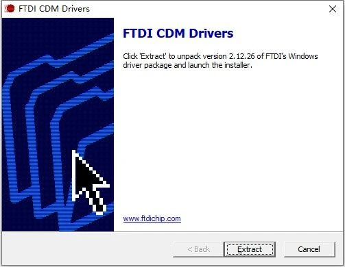
Figure 16
2. Click "Next."
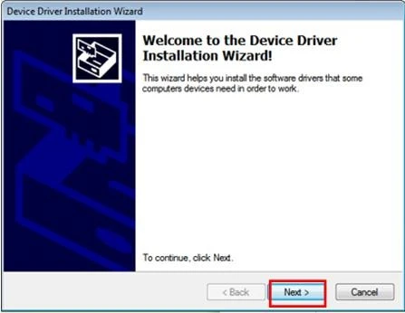
Figure 17
3. Select "I accept this agreement" and click "Next."
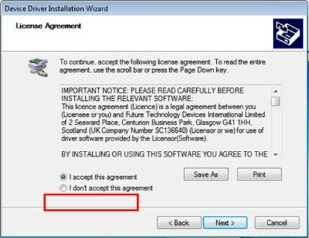
Figure 18
4. Wait for the installation to complete.
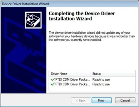
Figure 19
10.1.1.2 Software Installation
10.1.1.3
1. Open the installation file from the software package and double-click to open it.
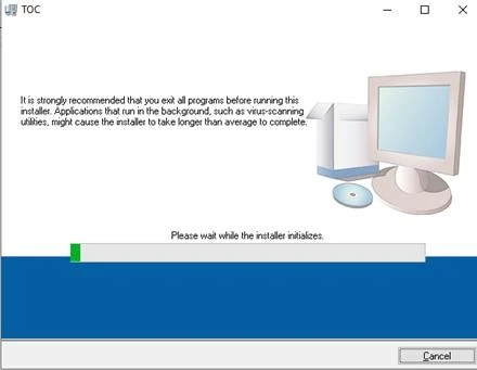
Figure 20
2. The default installation path is the D drive. Set it to a drive with running authorization if needed.
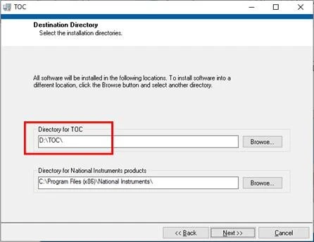
Figure 21
3. Select "I accept the above two license agreements" and click "Next."
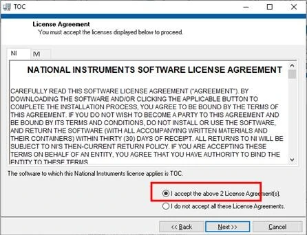
Figure 22
4. Click "Next."
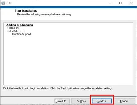
Figure 23
5. Wait for the installation to complete.
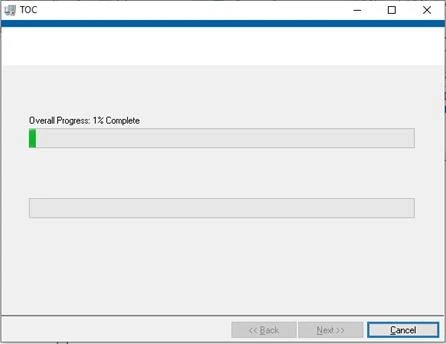
Figure 24
6. After installation, follow the prompts to click "Next" and restart the computer. A software shortcut will appear on the desktop.
10.1.2 Software Operation
10.1.2.1 Open Software
Double-click the software icon  to enter the main interface.
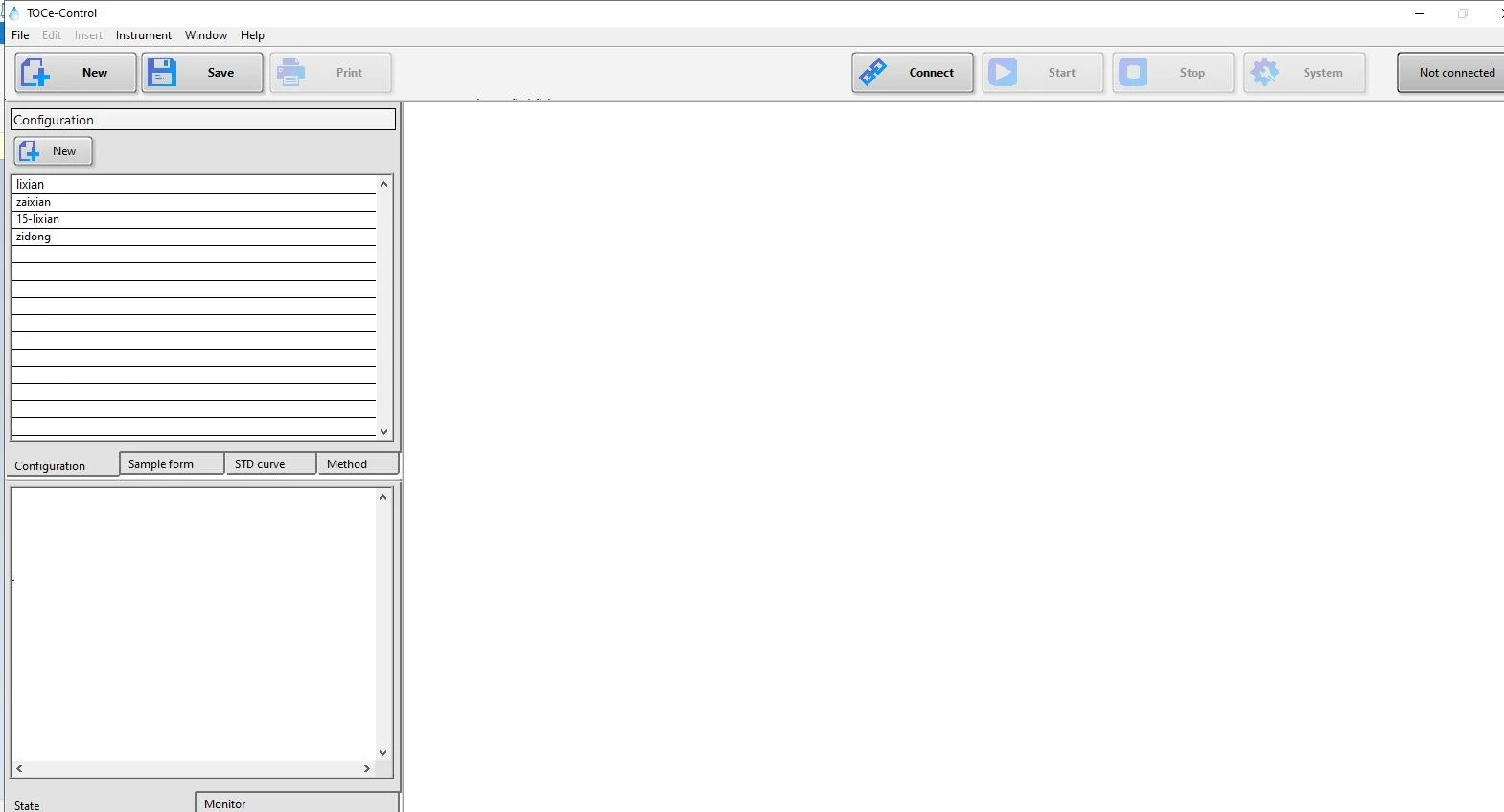
Figure 25
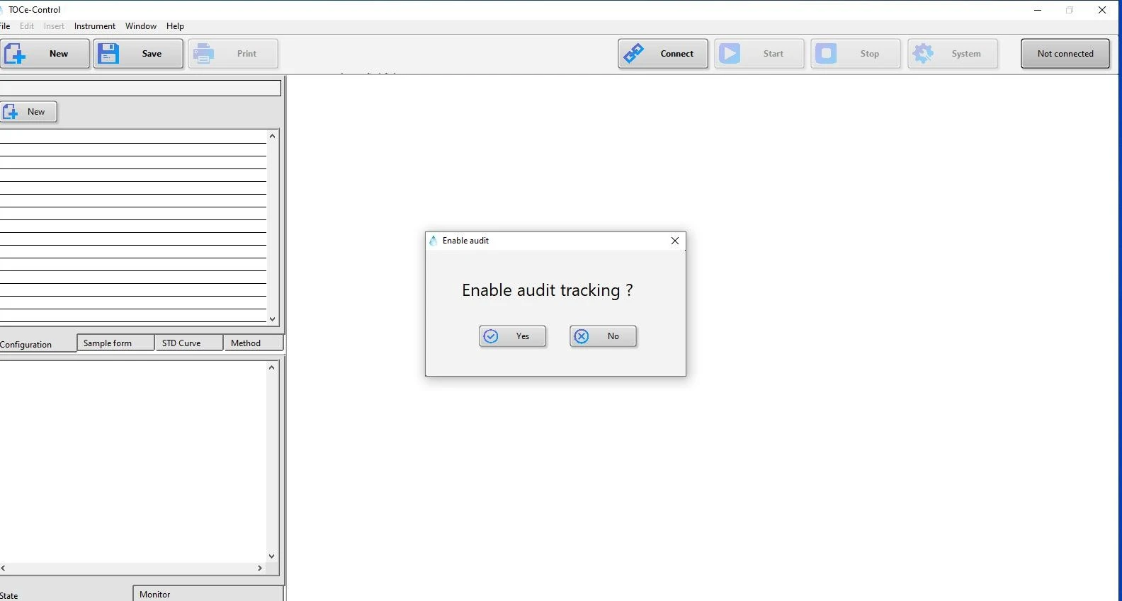
Figure 26
Note:
When you open the software for the first time after installation, a prompt will appear to configure the audit trail function (Figure 6.11). You can configure it according to your actual needs.
For operations related to the audit trail, please refer to the audit trail software manual.
10.1.2.2 Create Hardware Configuration
1. Click "Hardware Configuration" under the "File Browser" tab and then click "New"
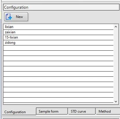
Figure 27
2. In the "Instrument Setup Wizard" interface, enter information such as "Hardware Name," and "Annotation." After completing the settings, click "Next".
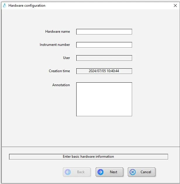
Figure 28
3. Follow the prompts to select the "Instrument Model," "Operating Mode," and "Accessories." After completing the settings, click "Next".
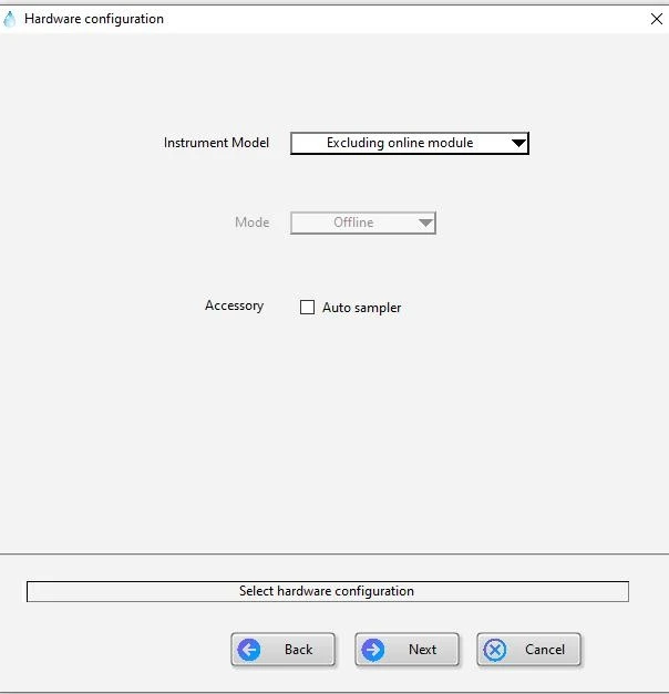
Figure 29
4. Configure the instrument communication parameters. After setting the ".Main unit port," click "Save".
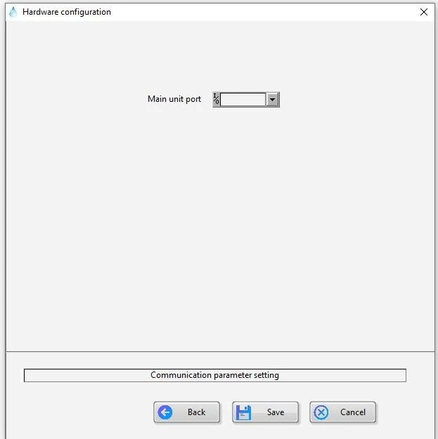
Figure 30
5.After saving, the configured hardware file will be displayed under "Hardware Configuration" in the File Browser tab.
Figure 31
10.1.2.3 Creating Sample Tables
1. Click "New" under the "Sample Table" in the File Browser tab, or click "New" in the toolbar.
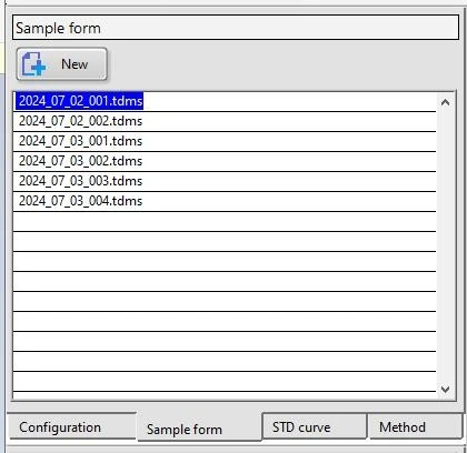
Figure 32
2. In the "Select Hardware Configuration" window, select the instrument hardware configuration.
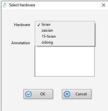
Figure 33
3. After creating the new sample table, it will be displayed in the designated area.
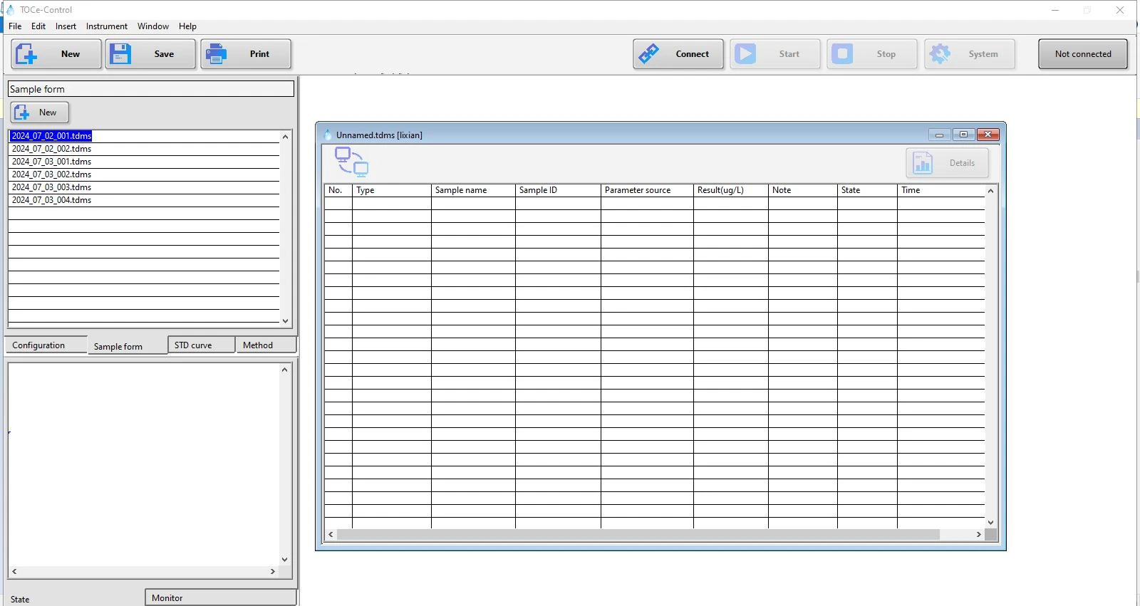
Figure 34
10.1.2.4 Creating Analysis Parameter Files
The purpose of creating a standard curve file is to set parameter information for measuring standard samples.
The purpose of creating a method file is to set analysis parameters for measuring unknown samples.
If these files already exist, the following steps can be skipped.
1. Standard Curve File
The steps to input the main parameters of the standard curve file are as follows:
1. Click "New" under "Standard Curve" in the File Browser tab.
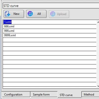
Figure 35
In the "New Standard Curve Parameters" interface, select the applicable "Hardware" for the standard curve. After completing the settings, click "Next".
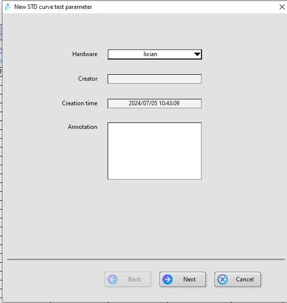
Figure 36
3. Enter the sample name, sample ID, and other information. Enter the file name in "Standard Curve File Name," and click "Save" to complete the standard curve configuration file.
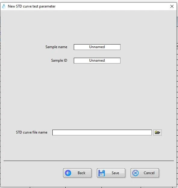
Figure 37
2. Method File
The steps to input the main parameters of the method file are as follows:
1. Click "New" under "Method" in the File Browser tab.
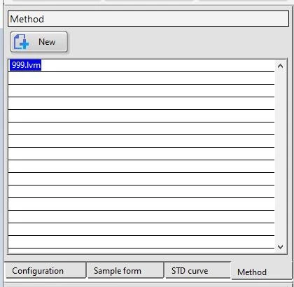
Figure 38
2. In the "New Method" interface, select the applicable "Hardware" for the method. After completing the settings, click "Next".
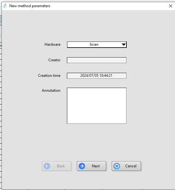
Figure 39
3. Enter the sample name, sample ID, and other information. Enter the file name in "Method File Name," and click "Next".
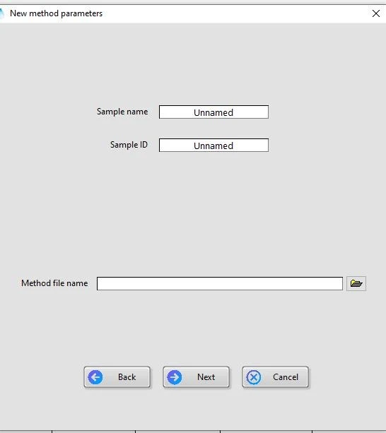
Figure 40
4. Select an already established standard curve as the reference for calculation. In offline mode, set the Number of Cleanings and measurements (Figure 6.26). In online mode, input the alarm threshold and sampling frequency parameters (Figure 6.27). Click "Save" to complete the setup.
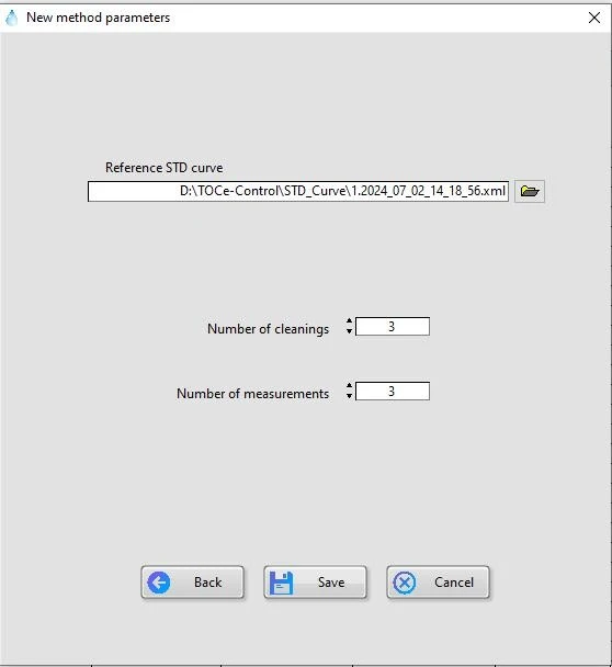
Figure 41
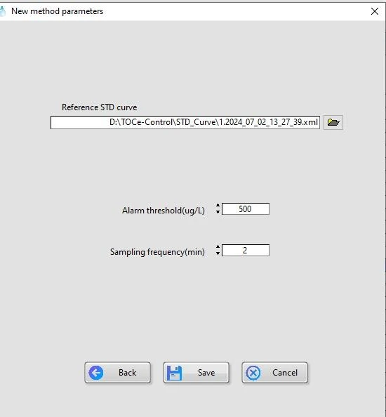
Figure 42
10.1.2.5 Editing the Sample Table
1. Insert Standard Curve Test into Sample Table
1. Select the newly created sample table window, right-click the blank area of the sample table, and choose "Insert Standard Curve" from the shortcut menu.
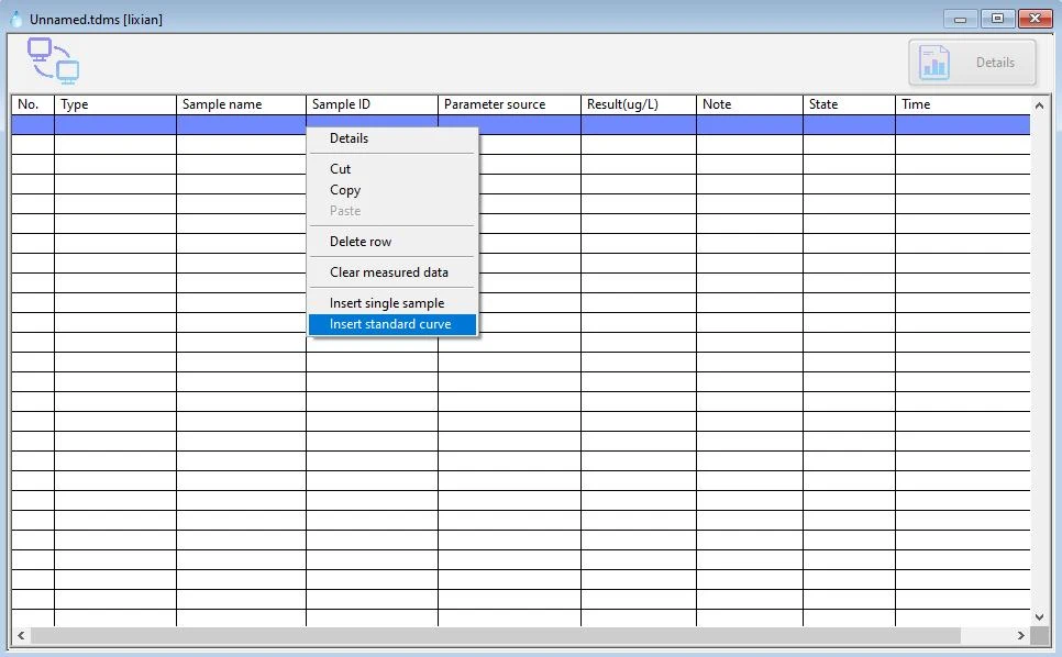
Figure 43
2. In the pop-up window, select the configured standard curve file and click "OK".
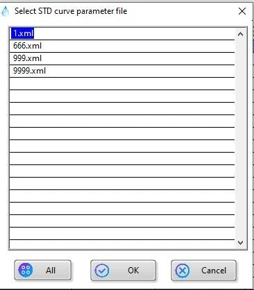
Figure 44
3. The standard curve test is added to the sample table.
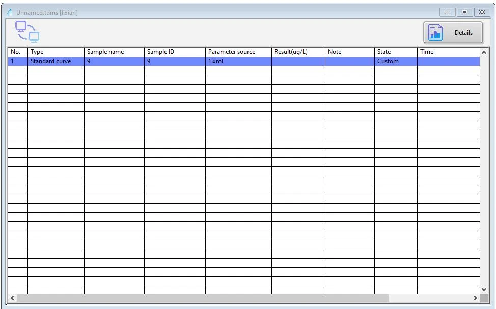
Figure 45
2. Insert Unknown Sample Test into Sample Table
1. Select the newly created sample table window, right-click the blank area of the sample table, and choose "Insert Single Sample" from the shortcut menu.
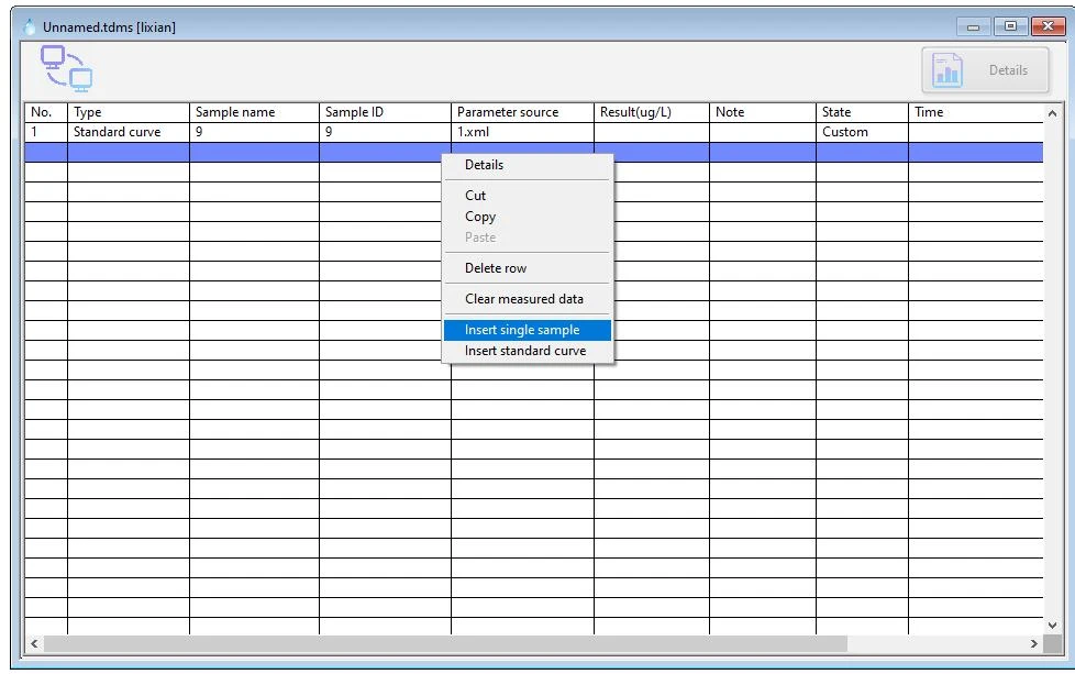
Figure 46
2. In the pop-up single sample parameter setting window, choose the method path, check "Skip remaining wizard pages, use source test parameters," and click "Save".
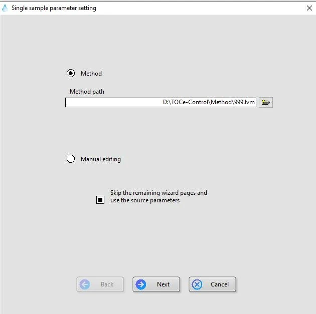
Figure 47
3. The unknown sample test is added to the sample table.
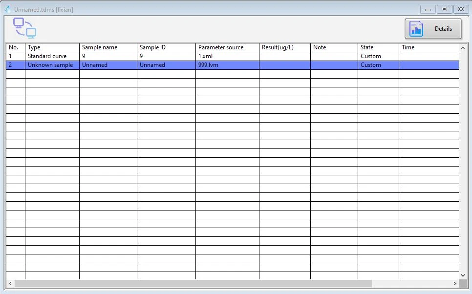
Figure 48
Note:
When analyzing multiple samples under the same conditions, you can use "Copy" and "Paste" to reinsert the samples into the sample table. The steps are as follows:
Select the desired sample row in the table, right-click and select "Copy", then right-click the blank row in the table and select "Paste", and the sample setup is completed.
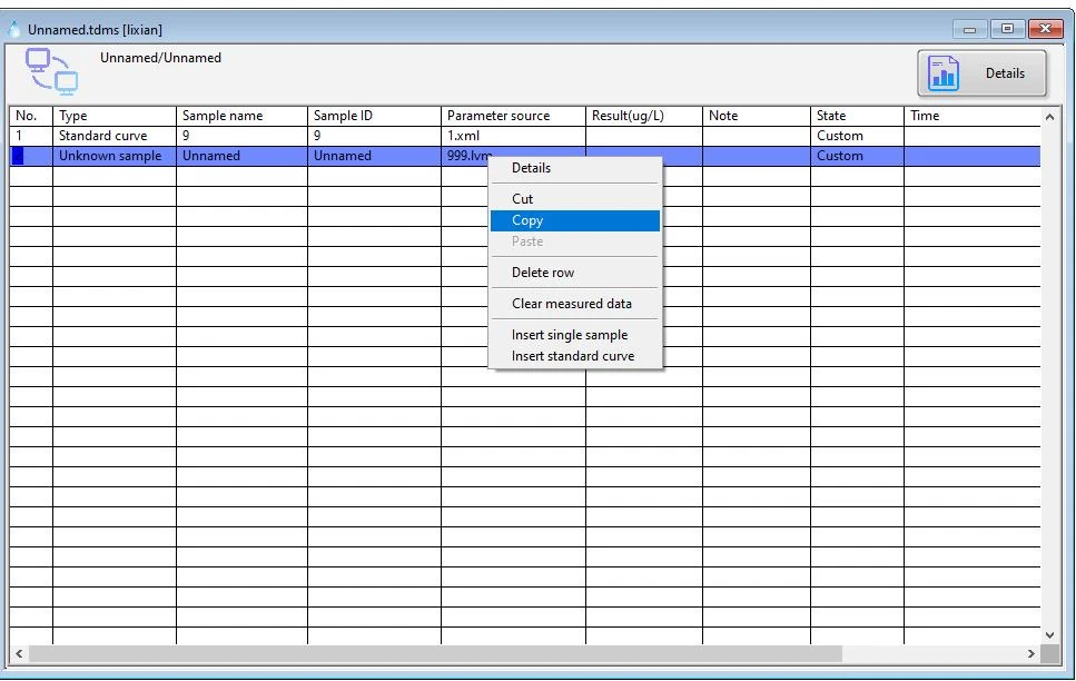
Figure 49
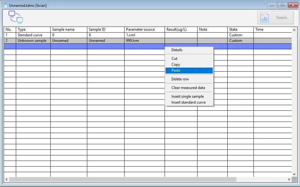
Figure 50
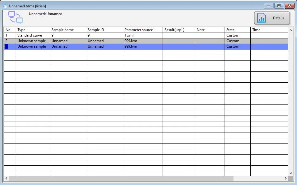
Figure 51
10.2 Standalone Operation
10.2.1 Logging into the System
1. Turn on the instrument power. The main interface appears as shown in Enter the 6-digit password and click the "Login" button. The factory default password is 123456. After logging in, you can change the login password in the "System Settings" interface.
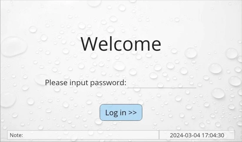
Figure 52
2. After successfully logging in, the interface will appear. Enter the operator's name and company name in the corresponding windows. The system will automatically record the previously entered information to avoid repeated input. After confirming the user information, click the "Confirm" button.
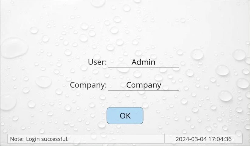
Figure 53
3. Enter the mode selection interface. The system has two modes to choose from: offline mode and online mode. Select the mode you need and click the "Confirm" button.
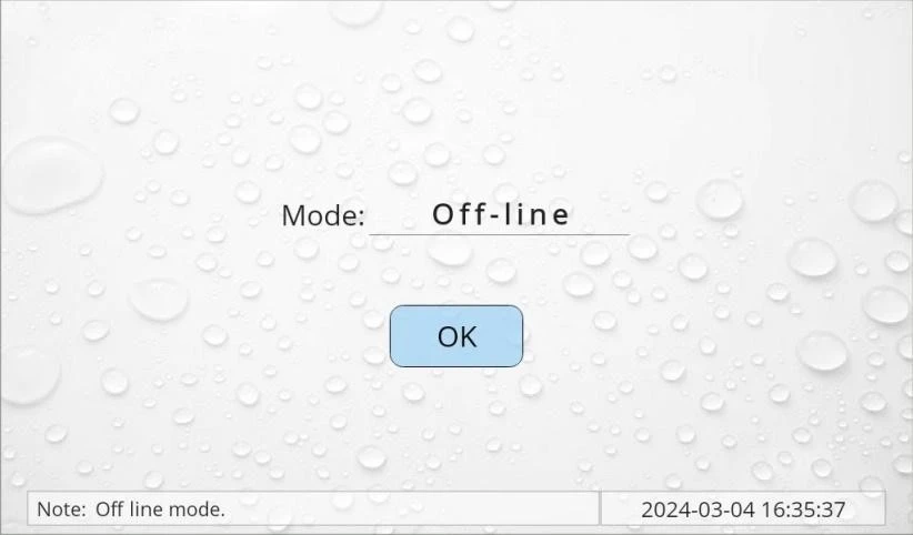
Figure 54
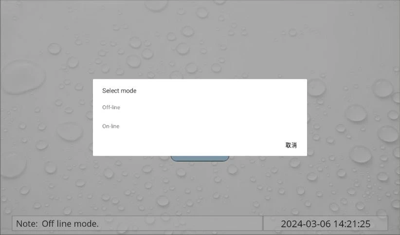
Figure 55
10.2.2 Measurement
10.2.2.1 Introduction to Offline Mode Measurement
The offline mode measurement interface.
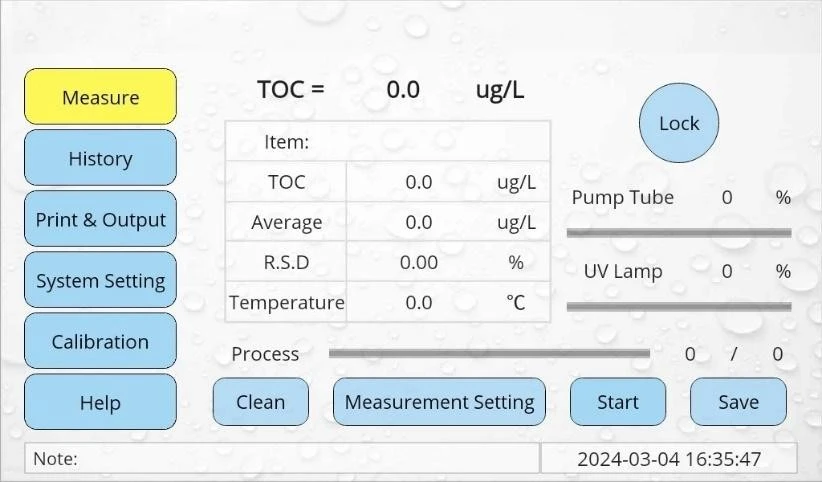
Figure 56
(1) After entering the main interface, the left side contains menu buttons, including "Measurement," "History," "Print & Output," "System Settings," "Calibration," and "Help." These buttons can be used to switch between interfaces when the system is not performing a measurement.
(2) The bottom of the interface displays operation prompts and time information.
(3) The central part of the interface is the offline mode measurement table, showing "Project Name," "TOC Test Value," "Average Value," "RSD," and "Temperature" data from top to bottom. The final test results are displayed at the top of the table in bold font.
(4) The lower part of the table contains a progress bar, with the current and total measurement counts displayed on the right side.
(5) On the right side of the table are progress bars indicating the usage status of the "Peristaltic Pump Tube" and "UV Lamp" in percentage form. Replace consumables promptly when their usage time is near expiration, and update the usage time information in the "System Settings" interface to recalculate usage time.
Measurement Interface Button Functions
"Lock":Click this button to lock the main interface when the system is not performing measurements. The main interface will switch to the welcome interface. To re-enter the system, you need to re-enter the login password.
"Clean":The clean button provides an interface dedicated to cleaning the pipelines, as shown in Thoroughly clean the instrument pipelines when first used after long storage or when measuring high concentration samples. In the cleaning interface, you can set the cleaning pump speed (1-50) and cleaning times (1-50) and display the TIC response value of the cleaning water during cleaning. Click the "Start" and "Stop" buttons to control the peristaltic pump, and click the "Exit" button to return to the measurement interface.
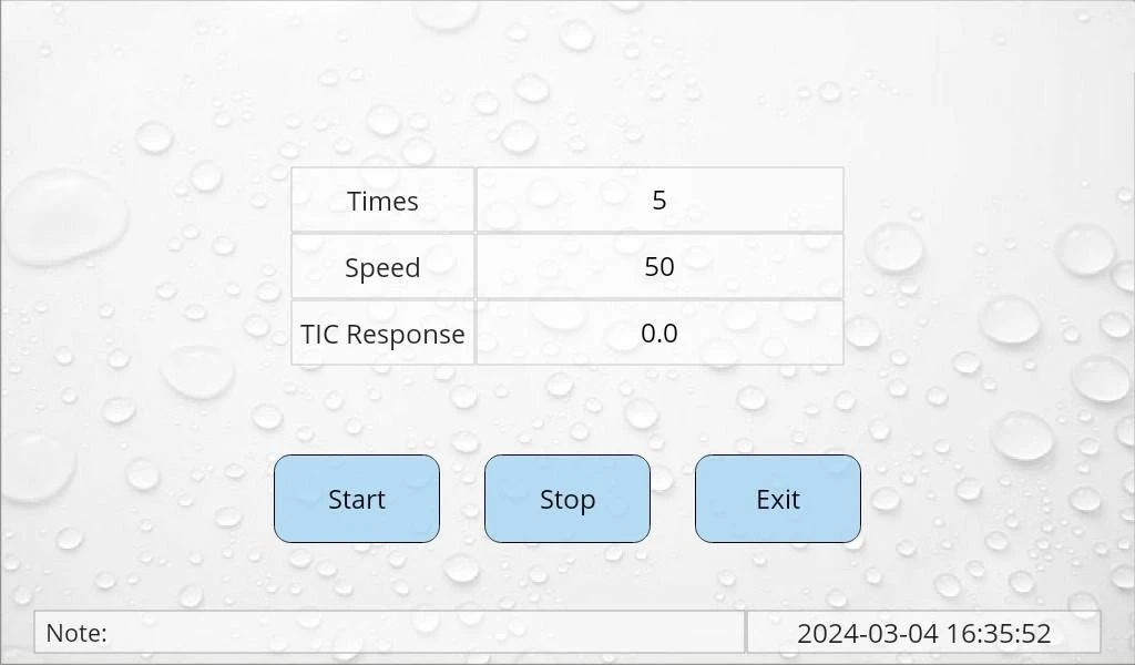
Figure 57
"Measurement Settings":Click this button to enter the "Measurement Settings" interface.In the measurement settings interface, enter the project name, cleaning times (0-50), and measurement times (1-50). The system provides default parameters, which can be modified if needed. Click the "Finish and Save" button to save the settings and return to the
measurement interface, or click the "Cancel" button to cancel the settings and return to the measurement interface.
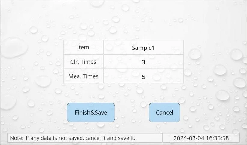
Figure 58
"Start":After finishing and saving the measurement settings, the "Project Name" set in the previous step will appear on the measurement interface. Click the "Start" button to begin measurement, changing it to a "Stop" button. During measurement, only the "Stop" button can be used; other buttons are disabled. The system performs cleaning and measurement operations in sequence based on the set cleaning and measurement times. The measurement results are displayed during cleaning but are not saved. After completing the measurement, the system automatically saves all measurement data.
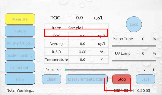
Figure 59
"Save":If you stop the measurement by clicking the "Stop" button before it finishes, data will not be saved automatically. To save the data, click the "Save" button.
10.2.2.2 Introduction to Online Mode Measurement
(1) The online mode measurement interface. The menu buttons, "Lock" button, consumable life record progress bar, prompts, time information, and measurement progress bar are the same as in offline mode and will not be repeated here. The far right of the measurement progress bar shows the current record count.
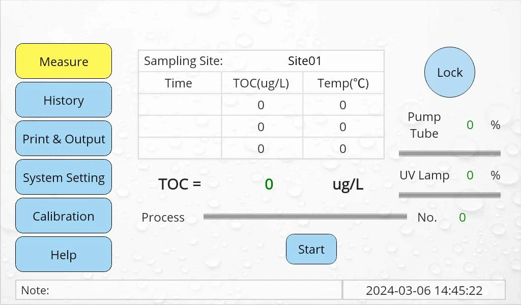
Figure 60
The top of the online mode measurement interface displays the sampling point, defaulted to "Site01." Click this default value to set the sampling point. The lower table shows the latest times, test data, and temperature from bottom to top, with the current test results displayed in bold at the bottom.
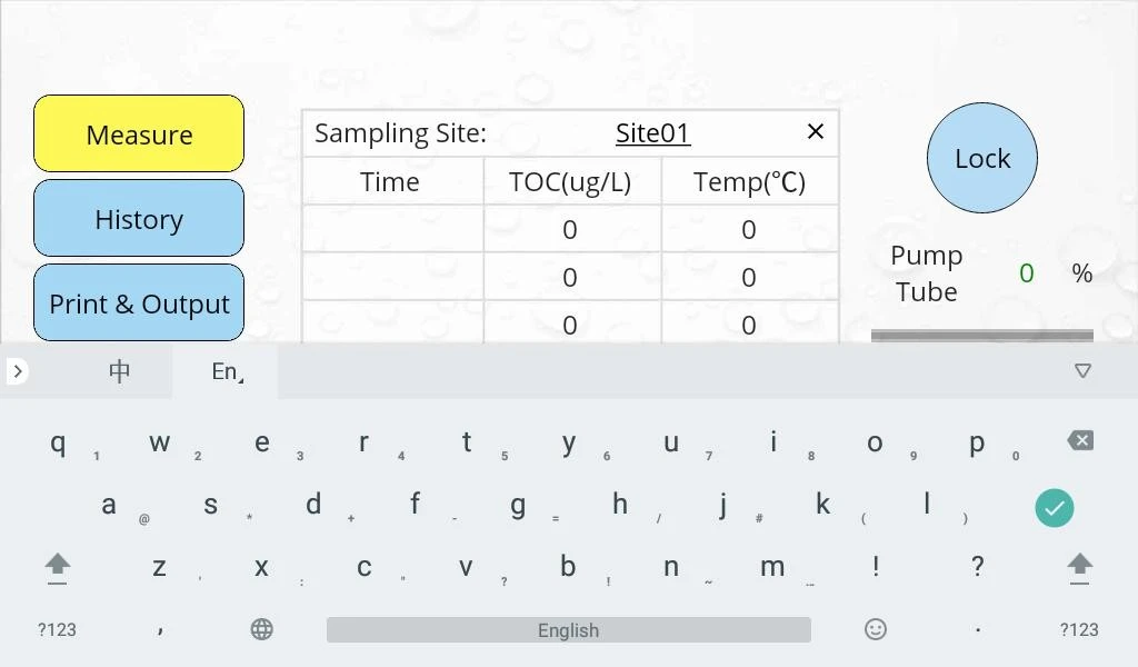
Figure 61
Click the "Start" button to enter the measurement process, changing it to a "Stop" button. During measurement, the system measures and records data sequentially. Other function buttons are disabled until you click "Stop." The data storage file is named based on the time you clicked start, making it easy to find later.
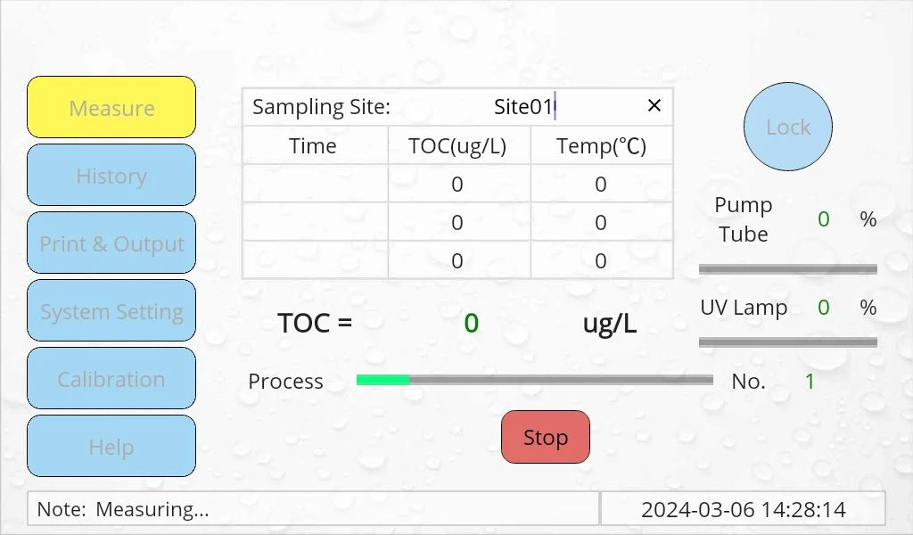
cc
10.2.3 History
When the system is not performing measurements, click the "History" menu button to enter the history query interface.
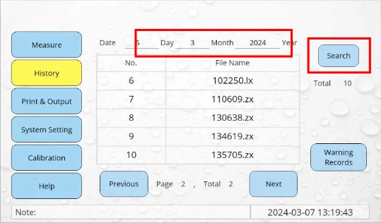
Figure 63
(1) In the history interface, enter the measurement date of the file to be queried, and click the "Search" button at the top right to display the file list in the table (Figure 6.48). Files with the ".lx" suffix are offline mode measurement files, while those with the ".zx" suffix are online mode measurement files. Click the "Previous " or "Next " buttons to browse remaining entries.
(2) Click any file name to view the corresponding data. Offline mode files including file name, measurement times, measurement time, average value, RSD, temperature, and all recorded data. Each page displays 10 entries. Click the "Previous " or "Next " buttons to view remaining data. Click the "Back" button to go back to the history main interface. Click the "Delete" button to return to the history main interface and clear the measurement record.
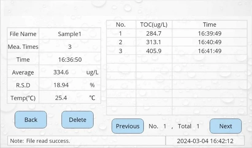
Figure 64
(3) Online mode files, including sampling point, date, and all recorded data. Each page displays 7 entries. Click the "Previous " or "Next " buttons to view remaining data. Click the "Back" button to go back to the history main interface. Click the "Delete" button to return to the history main interface and clear the measurement record.
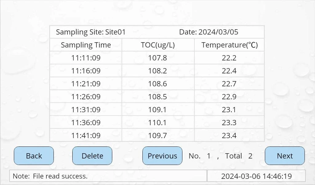
Figure 65
Click the "Warning Records" button to enter the alarm records interface.Alarm records include information about alarms triggered by measurements exceeding the range or alarm values. Click the "Copy" button in the alarm records interface to export alarm records to a USB drive. Click the "Previous " or "Next " buttons to browse remaining entries. Click the "Back" button to go back to the history main interface.
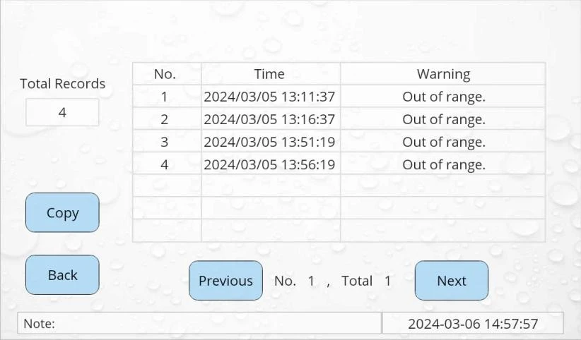
Figure 66
10.2.4 Print & Output
When the system is not performing measurements, click the "Print & Output" menu button to enter the print output interface.
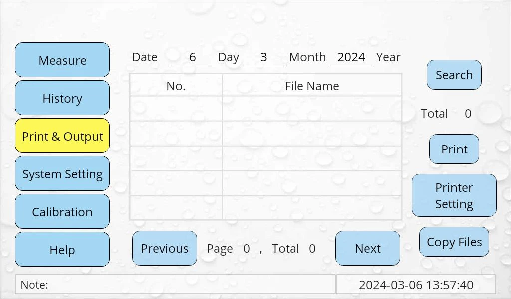
Figure 67
(1) Similar to the history interface, enter the time information and click the "Query" button to display the file list in the table. Click the "Previous Page" or "Next Page" buttons to browse remaining entries.
(2) Insert a USB drive into the USB port on the right side of the main unit. Click the "Copy Files" button to automatically copy all files within that date to the USB drive, stored in a folder named with the date information (e.g., "161020" represents October 20, 2016). If a folder with the same name already exists on the USB drive, an error message will appear. In this case, delete the folder on the USB drive before copying.
(3) Before shipping, the printer and main unit have been set up for Bluetooth connection, so there is no need to perform "Printer Settings." Turn on the printer, wait about a minute, select the target file, and click the "Print" button to complete data printing.
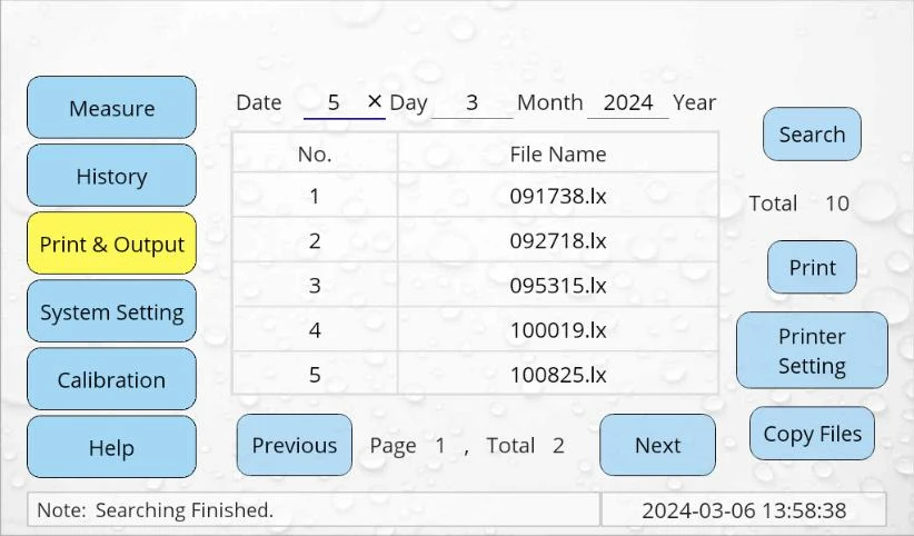
Figure 68
Note:
If the prompt at the bottom indicates "Please set the printer in the printer settings interface," it means the printer connection failed. Restart the main unit and printer, and try again. If it still fails, click the "Printer Setting" button to enter the printer settings interface. Enter the BIND and PSWD codes in the corresponding windows, following the default settings format. Refer to the printer manual for obtaining the BIND and PSWD codes. After confirming the settings, click the "Connect" button. This pairing may take 1-2 minutes. If the connection fails, check the input and try reconnecting. If it still fails, contact after-sales support. Once connected, click the "Back" button.
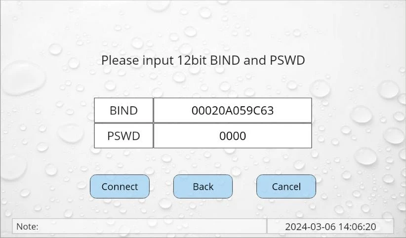
Figure 69
10.2.5 System Settings
When the system is not performing measurements, click the "System Setting" menu button to enter the system settings login interface. The initial password is 00000001. Click the "OK" button to enter the system settings interface. In the system settings interface, you can view and set the basic parameters of the instrument.
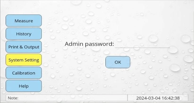
Figure 70
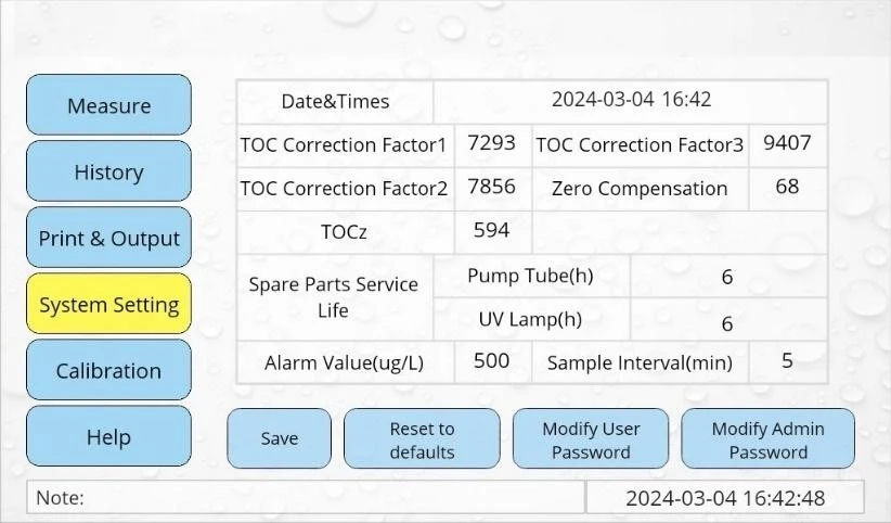
Figure 71
(1) Click the box to the right of "Date & Time" to set the system time and date.
(2) Click the boxes to the right of each item to set the corresponding parameters. The "Zero Compensation," "TOCz," and "TOC Correction Factor 1, 2, and 3" need to be set based on calibration results. "Pump Tube" and "UV Lamp" are used to set the used time information. After replacing the corresponding parts, reset the data. The "Alarm Value (ug/L)" sets the alarm value for online mode. When running in online mode, if the measurement result exceeds the alarm value, the buzzer will sound an alarm and record the alarm information. "Sampling Interval (minutes)" sets the sampling interval time for online mode, ranging from 5-120 minutes.
(3) After setting all parameters, click the "Save" button to save all parameters.
(4) To restore factory settings, click the "Reset to defaults" button.
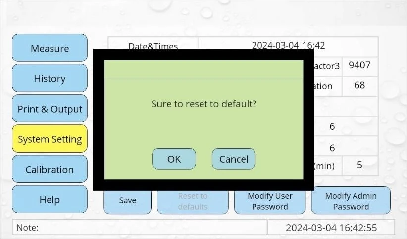
Figure 73
(5)Click "Modify User Password" or " Modify Admin Password" to modify the system login password and system settings login password, respectively. To change the password, correctly enter the old password, then enter the new password twice, and click the "OK" button to complete the modification. The user password is 6 digits, and the admin password is 8 digits. If the input format is incorrect, re-enter the information.
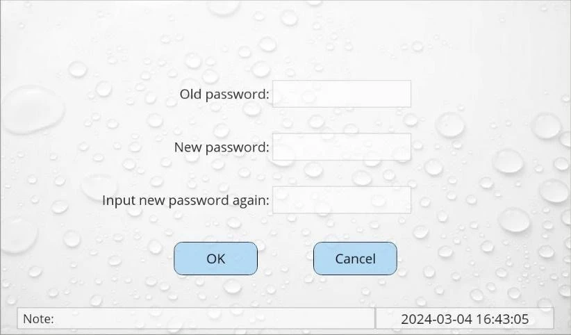
Figure 75
10.2.6 Calibration
Calibration involves a total of 16 steps. Please follow the prompts step-by-step to complete the calibration process.
1. When the system is not performing any measurement operations, click the "Calibration" menu button to enter the calibration interface. Follow the prompt to insert the sampling tube into the zero calibration water and click the "Start" button.
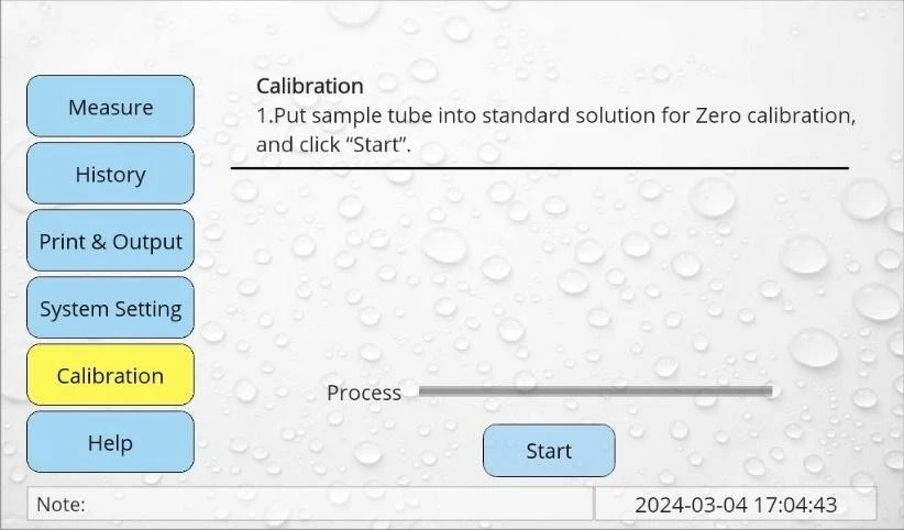
Figure 76
The system will automatically measure the TC and TIC values of the zero calibration water and calculate the compensation value. The system will automatically stop when the RSD of the TC and TIC measurements is less than 0.5% for three consecutive measurements. This calibration usually takes about 20 minutes. If the system has recently tested high concentration samples or has not been used for a long time, it may take longer. Each measurement result is updated in real time for easy observation. If you want to stop the calibration, click the "Stop" button.
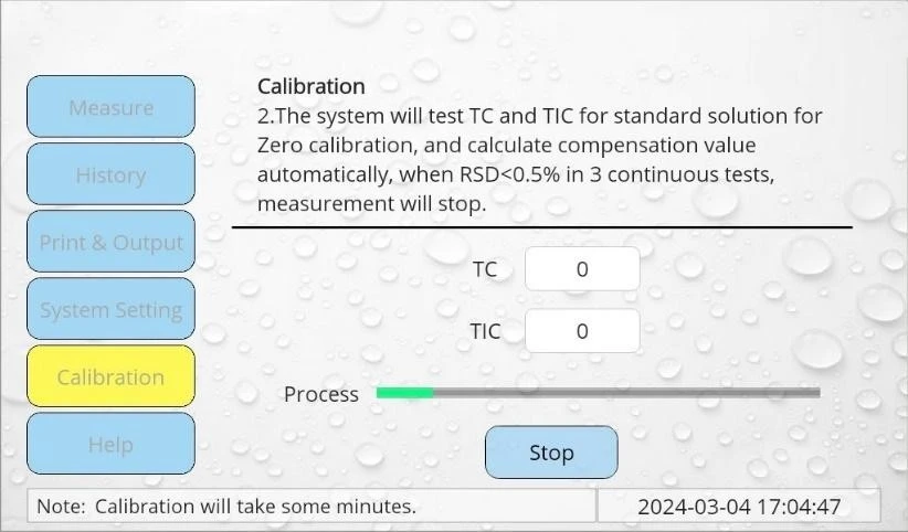
Figure 77
3. The zero compensation value is calculated as the average TC value of three consecutive measurements minus the average TIC value of three consecutive measurements. The system automatically calculates this value and displays it on the screen. Record the zero compensation value in the box below and enter it into the system parameters after calibration is complete. Click the "Next" button to continue the calibration; if you are not satisfied with the measurement results, click the "Previous" button to return to step 1 and retest.
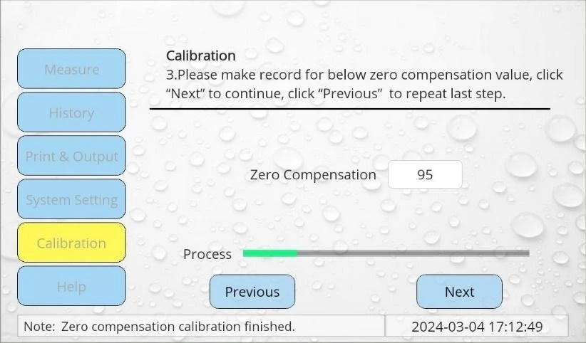
Figure 78
4. Measure the zero calibration water to obtain the TOC response value of the zero calibration water. Do not remove the sampling tube from the zero calibration water. Click the "Start" button to continue the calibration process or the "Cancel" button to cancel the calibration.
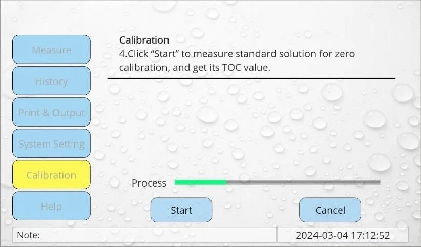
Figure 79
5. The system will automatically measure the TOC response value of the zero calibration water and display it on the screen, as shown in Figure 6.63. The system will automatically stop when the RSD of three consecutive measurements is less than 2%, and the average of these three measurements will be recorded as TOCz. To stop the calibration process, click the "Stop" button.
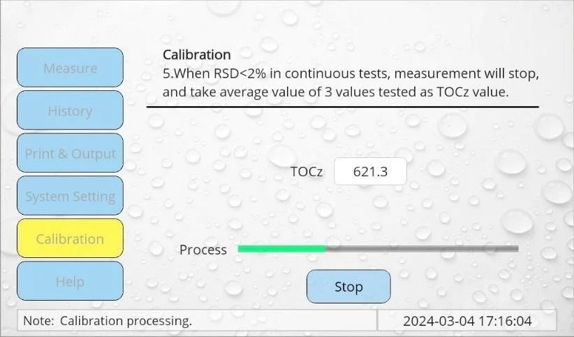
Figure 80
6. The TOCz result is displayed as shown in Figure 6.64. Record the TOCz value in the box,
which will be used to calculate the organic carbon calibration constant at the end of the calibration. Click the "Next" button to continue the calibration; if you are not satisfied with the measurement results, click the "Previous" button to return to step 4 and retest.
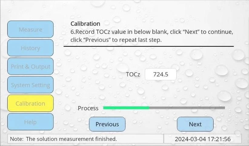
Figure 81
7. Insert the sampling tube into the 200 μg/L sucrose calibration solution. Click the "Start" button to continue the calibration or the "Cancel" button to exit the calibration process.
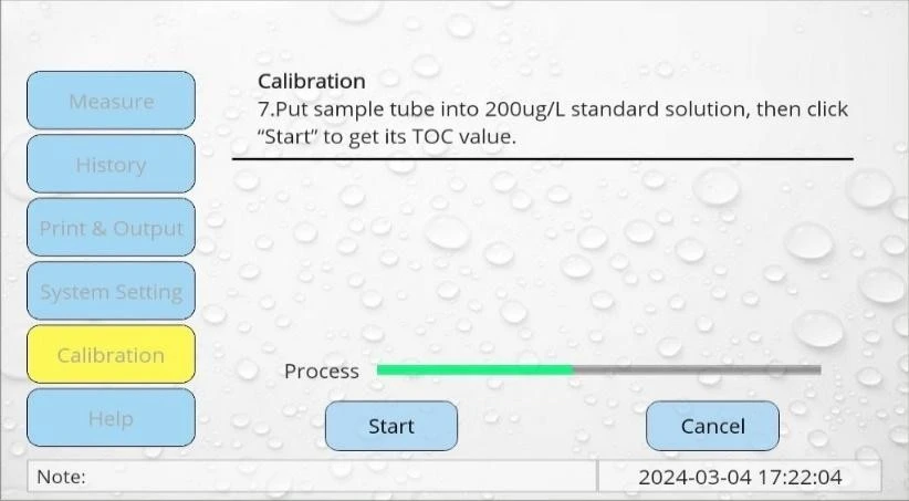
Figure 82
8. The system will automatically measure the TOC response value of the 200 μg/L sucrose calibration solution and display it on the screen, as shown in Figure 6.66. The system will automatically stop when the RSD of three consecutive measurements is less than 1%, and the average of these three measurements will be recorded as TOCs1. To stop the calibration process, click the "Stop" button.
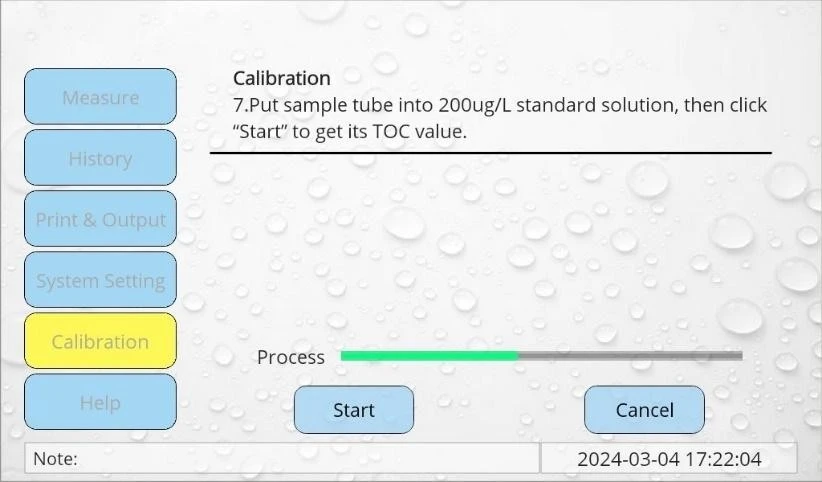
Figure 83
9. The TOCs1 result is displayed.Record the TOCs1 value in the box, which will be used to calculate the organic carbon calibration constant at the end of the calibration. Click the "Next" button to continue the calibration; if you are not satisfied with the measurement results, click the "Previous" button to return to step 7 and retest.
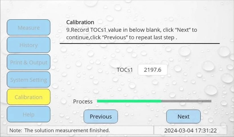
Figure 83
10. Insert the sampling tube into the 500 μg/L sucrose calibration solution. Click the "Start" button to continue the calibration or the "Cancel" button to exit the calibration process.
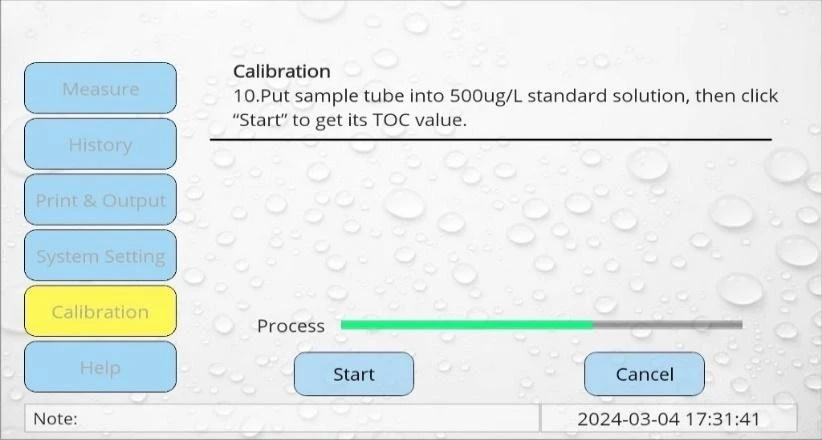
Figure 84
11. The system will automatically measure the TOC response value of the 500 μg/L sucrose calibration solution and display it on the screen, as shown in Figure 6.69. The system will automatically stop when the RSD of three consecutive measurements is less than 0.5%, and the average of these three measurements will be recorded as TOCs2. To stop the calibration process, click the "Stop" button.
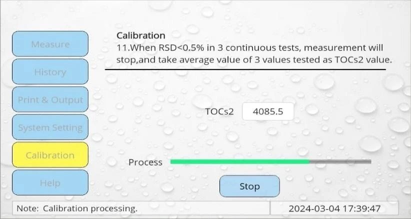
Figure 85
12. The TOCs2 result is displayed. Record the TOCs2 value in the box, which will be used to calculate the organic carbon calibration constant at the end of the calibration. Click the "Next" button to continue the calibration; if you are not satisfied with the measurement results, click the "Previous" button to return to step 10 and retest.
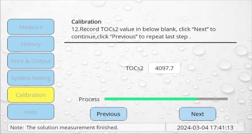
Figure 86
13. Insert the sampling tube into the 1000 μg/L sucrose calibration solution. Click the "Start" button to continue the calibration or the "Cancel" button to exit the calibration process.
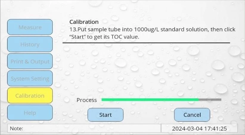
Figure 87
14. The system will automatically measure the TOC response value of the 1000 μg/L sucrose calibration solution and display it on the screen. The system will automatically stop when the RSD of three consecutive measurements is less than 0.5%, and the average of these three measurements will be recorded as TOCs3. To stop the calibration process, click the "Stop" button.
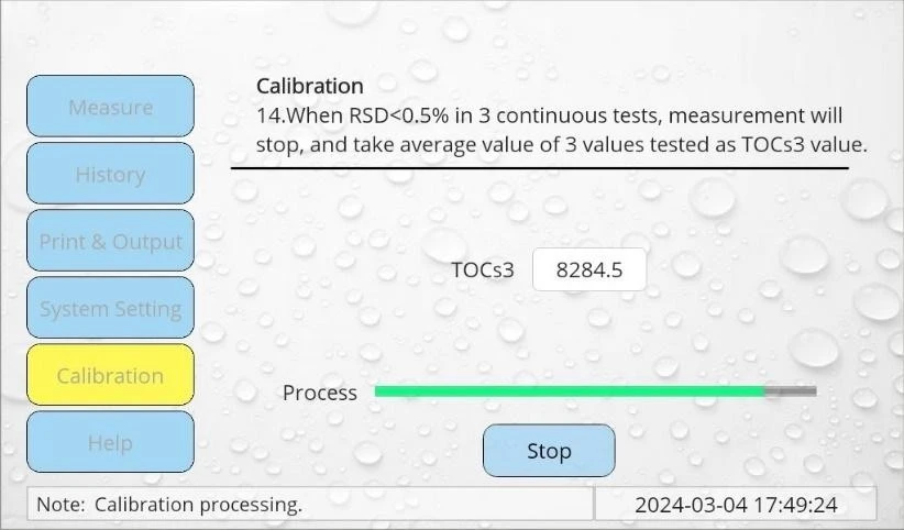
Figure 88
15. The TOCs3 result is displayed. Record the TOCs3 value in the box, which will be used to calculate the organic carbon calibration constant at the end of the calibration. Click the "Next" button to continue the calibration; if you are not satisfied with the measurement results, click the "Previous" button to return to step 13 and retest.
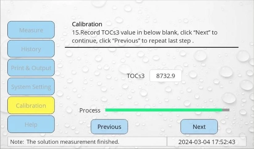
Figure 89
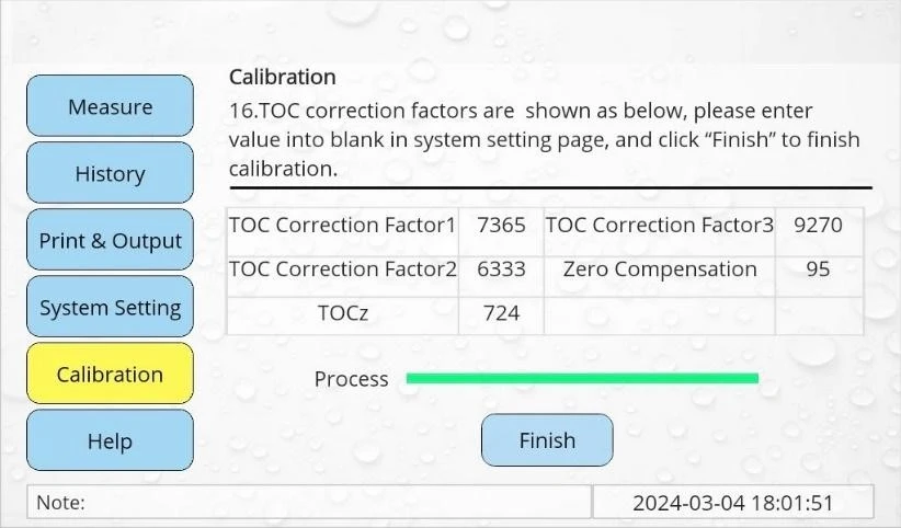
16. The system will analyze the results based on the tests. If the calibration fails, you need to re-prepare the calibration solution and redo the calibration process. If the calibration is successful, the system will automatically calculate the total organic carbon calibration constant and display it on the screen. Record the three total organic carbon calibration constants, the zero compensation value, and the zero response value in the boxes. Click the "Finish" button, and the interface will switch to the system settings login interface. Enter the system settings and input the recorded values into the corresponding boxes in the system settings, then click "Save."