Get Price
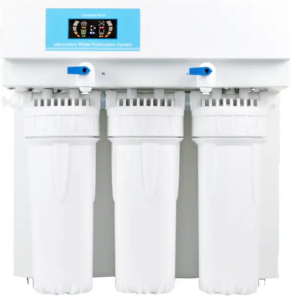
Pure Water Supply System BBPS-107
This basic series is ideal for a wide range of applications. It produces RO, Deionized water and Ultrapure water. The organic rejection rate is greater than 99% using reverse osmosis. The resistivity reaches up to 18.2M?.cm which completely meets the highest grade I standard.
- Automatic microcomputer controlling system, LED real-time animation mode display.
- Running status is shown in the LED, such as flushing, producing water, full tank, water shortage, leakage and service.
- Power on self test, power reset, alarm when work more than 6 hours continuously, water shortage, leakage, low pressure and high pressure.
- 3 procedure of the reverse osmosis membrane's self-flushing: power on, water shortage reset and work more than 2 hours continuously, extend the life of RO membrane.
- Up to 3-Year Product Warranty
- US & EU Compliance Standards
- Door-to-Door Shipping
Technical Specifications
Detailed operating and construction parameters for this model.
| Model | BBPS-107 |
| Water Inlet | Tap water: TDS<200 ppm (Extra pretreatment filter is recommended, if TDS>200 ppm) |
| Temperature | 5-45°C |
| Pressure | 1.0-4.0 Kgf/cm² |
| Flow Procedure | PF+AC+RO+DI |
| Ion rejection rate | 96%-99% (New RO membrane) |
| Organic rejection rate | >99% (when MW>200 Dalton) |
| Particles and bacteria rejection rate | >99% |
| Bacteria | <0.1 cfu/ml (with terminal filter) |
| Output (25°C) | 15 L/hrs |
| Pure water outlet | RO and deionized water |
| Dimension LxWxH | 410x320x420 mm |
| Weight | 15 kg |
| Standard configuration | Main body (Including 1 set of cartridges) + TDS pen + accessory bag |
| Power Consumption (W) | 72 W |
| Power Supply | AC110-220 V, 50/60 Hz |
| Note | *The feed water quality will influence the pure water's quality and cartridges life-span. PF: polypropylene spun fiber, AC: active carbon, RO: reverse osmosis, DI: ion exchange. Specifications tested under feed water TDS=200 ppm, 25°C, 50 psi and 15% recovery rate. |
| Deionized water quality | |
| Resistivity | >13-17.5 MΩ·cm |
| Conductivity | 0.057-0.077 μS/cm |
| Particle (>0.2μm) | Particle (>0.2 μm) <1/ml (with terminal filter) |
Product Features
Key design, performance, usability, and safety advantages.
Applications Explore common laboratory, research, industrial, and process applications.
Laboratory, Manufacturing, Reefkeeping, Aquarium
Operating Manual View instructions, operating procedures, safety information, and maintenance guidance.
1. Preface
2. Specification
3. Water Flow Chart
4. Working Environments
5. Installation
5.1 Preparation for installation
5.2 Tube and adapter's connection
5.3 Installation steps
6. Specification of Microcomputer Controller
6.1 Specification of status icons
6.2 Mode of connection
6.3 Technique data
6.4 Filters management
7. Usage Guide
8. Water Quality Test
9. Consumables
10. Normal Trouble Diagnosis
11. Warranty & Repair Regulation
1. Preface
Dear customer, in the beginning, we sincerely thanks for your choosing our water purification system. This water purification system has incorporated new cutting-edge technology. It is installed and used easily, and can provide you with RO water and ultrapure water for science research. So, it will benefit your work.
For the water purification system's maximum efficiency, it is suggested that the user manual should be read before installation. Any question in the installation process, please contact our technology engineers or dealers.
2. Specification
Model | BBPS-107 |
Output(25°C)* | 15 liters/hour |
Flow rate | Up to 2 liters/minute (with pressure tank) |
Pure water outlet | 2: reverse osmosis water, deionized water |
Deionized water quality | |
Resistivity | 13-17.5MΩ.cm |
Bacteria | <0.1cfu/ml (with optional 0.2μm PES terminal filter) |
Particles (>0.2μm) | <1/ml (with optional 0.2μm PES terminal filter) |
RO water quality | |
Ion rejection rate | 98-99%(with new RO membrane) |
Organics rejection rate | >99% (when MW>200 Dalton) |
Particles and bacteria rejection rate | >99% |
Feed water requirements | Tap water, temperature:5-35°C,pressure:1.0-4.0bar |
Pure water outlet | RO water, deionized water |
Dimension/weight | Length xWidth xHeight: 340x320x470mm/ Weight: about 15Kg |
Electrical requirements | AC100-240V,50/60Hz |
Power | 72W |
Standard configuration | Main body (Including 1 set of cartridge) |
Purification System | ||
Sequence number | Specification | Quantity/set |
LV.1 | 10" spun fiber filter | 1 |
LV.2 | 10" active carbon block filter | 1 |
LV.3 | 100GPD RO membrane(15) | 1 |
200GPD RO membrane(30) | 1 | |
300GPD RO membrane(45) | 1 | |
LV.4 | Mixed bed resin cartridge | 2(15)/3(30) |
7.7L Mixed bed resin cartridge | 1(45) | |
Table 1
REMARKS:
* The value will be influenced by temperature and feed water's quality.
3. Water Flow Chart

Figure 1
4. Working Environments
• Inlet water: Tap water (TDS<200ppm will be suggested).
If inlet water TDS>200ppm, pretreatment is recommended. Water with higher TDS will affect the quality of outlet water and life of purification cartridge.
• Work temperature: 5-45°C
• Pressure: 1.0-4.0bar
• Power: AC100-240,50/60Hz,72-120W
【Clean, dry working environments would be suggested!】
5. Installation
5.1 Preparation for installation
The purification system should be installed horizontally and near to tap.
5.2 Tube and adapter's connection
The adapter of the machine is high quality easy-put adapter. And material of tube is high quality's PE.
Tube installation and drag diagram

Figure 2
 ATTENTION:
The tube should be cut with special tube cutter for rounded cut section. And rounded cut section should be guaranteed as much as possible with other cut tools.
Connect the tube-press the oval cap of the interface strongly, then insert the tube to the bottom of adapter.
Take off the tube-press the oval cap of the interface strongly, then drag out the tube. Do not drag when the tube can't be dragged out any more.
The fore-end of the tube, which has been inserted to adapter, should be cut, when it will be used again.
Sufficient PTFE thread seal tape should be used in all the threaded joints for water leakage inhibitor or preventing.
5.3 Installation steps
(1). Open the packing-case, take out main body, accessory box, water tank (optional).
(2). Take out adapters and tube from accessory box, and read the Instruction Manual carefully.
(3). External interface are on the back of machine, and it is labeled with different color's label. Moreover, its adapters are inserted with different color's stop plug.
ATTENTION:
Stop plug should be pulled out before the following steps.
(4). Connect To Tap Water
There are two ways to connect to the tap.
Guide Chart of 2 Ways to Connect To The Tap

Figure 3
1st way-with tap water adapter 1(1/2″internal thread to 3/8″fast-plug) to connect to tap water.
1st. Step: connect tap water adapter 1 to water source
Close the valve of the gooseneck. Dismantle the faucet of gooseneck. Screw tap water adapter 1 into the external thread of gooseneck.
2nd. Step: connect tap water adapter 1 to interface of machine's inlet water
Use 3/8" PE tube with a suitable length. Insert one side into the interface of tap water adapter 1, and insert the other into the interface with blue label marked "To inlet water" at the back of machine.
2nd way-with tap water adapter 2(tee joint and 3/8″ball valve) to connect to tap water.
1st. Step: connect tap water adapter 2 to water source
Close the chief valve of tap water. Dismantle the tap.
Screw the 3/8'' ball valve with external thread into the side thread with internal thread of tee joint. Screw the tap into the internal thread at one end of the tee joint, and at last, screw the other end with external thread of the tee joint(with 3/8'' ball valve and the tap at this time) into the internal thread of the tube, where the tap has been connected.
 ATTENTION:
Sufficient PTFE thread seal tape should be used in all the threaded joints for water leakage inhibitor or preventing
2nd. Step: connect tap water adapter 2(3/8″ball valve) to interface of machine's inlet water
Use 3/8" PE tube with a suitable length. Insert one side into the interface of 3/8 ″ ball valve, and insert the other into the interface with blue label marked "To inlet water" at the back of machine.
ATTENTION:
Extra pretreatment filters (optional) should be connected between the water source and main body.
(5). Connect To RO Wastewater
Use 1/4" PE tube with a suitable length. Insert one side into the interface with black label marked "To drain" at the back of machine, and the other side is directed to drain. (DO NOT JAM!!)
Thus the installation is OK.
Installation Guide Chart

Figure 4

Figure 5
6. Specification of Microcomputer Controller

Figure 6
6.1 Specification of status icons
Status | Working Status |
| The flushing identifier is flashing when the system is in flushing status; The flushing identifier is being bright when it is finished. Turn on the power, the system would automatically flush about 30 seconds; When it is full of water, the system would automatically flush about 10 seconds; After quit the process of lacking water, the system would automatically flush about 30 seconds; (High-pressure pump work,inlet valve open,flush valve open) |
| The produce water identifier is flashing when the system is in producing water status; The produce water identifier is being bright when it is finished. It enters the producing water process after detecting the low-pressure switch and high-pressure switch shut off. (High-pressure pump work,inlet valve open,flush valve open) |
| The full identifier is flashing when the system is in full water status, and the produce water, check, flashing, lack identifier is being bright. The system would enter the process of full water, when the water pressure of the high-pressure switch equal to the setting value. (High-pressure pump work,inlet valve open,flush valve open) |
| The lack identifier is flashing when the system is in lacking water status; The lack identifier is being bright when it is finished. The system would enter the process of lacking water, and be alarming for 10 times, when the water pressure of the low-pressure switch lower than the setting value. (High-pressure pump work,inlet valve open,flush valve open) |
| The check identifier is flashing when the system is in check status; The check identifier is being bright when it is not. The system would enter the process of check, and be alarming for 30 times, when no full water after continuous work for 6 hours. It will in normal work after power on again. (High-pressure pump work,inlet valve open,flush valve open) |
Backlight | The backlight will go out after 120 seconds when the system is in full water status. The backlight is being bright for the rest. |
TDS | Raw water TDS value range is 0-999μs/cmμs/cm (RO water value) Pure water TDS value range is 0-199μs/cm (DI water value) |


Table 2
6.2 Mode of connection
Serial Number | Color | Layout | Serial Number | Color | Layout | Serial Number | Color | Layout |
1 | Yellow | Low-pressure switch | 6 | Black | Inlet valve | 11 | White | 24Vdc |
2 | Blue | High-pressure switch | 7 | Yellow | Low-pressure switch | 12 | Pink | 24Vdc |
3 | Blue | High-pressure switch | 8 | Green | Pump | |||
4 | Red | Flush valve | 9 | Black | Inlet valve | |||
5 | Green | Pump | 10 | Red | Flush valve |
Table 3
P4- RO water connection port: single way TDS sensor P5- DI water connection port: single way TDS sensor
6.3 Technique data
1,Working mode:continuous work for a long time
2,Working voltage:DC24V
3,Power:<1.5W(MAx)
4,Load current:3.5A
5,Working temperature:-20°C - +70°C
6,Load voltage:24VDC
7,Working moisture:5%-85%
6.4 Filters management
(1). The filters service life is calculated depending on the accumulated working time of pump, and all the filters are listed as below:
Filter 1: 450 hours (10" spun fiber filter)
Filter 2: 900 hours (10"granular active carbon filter) Filter 3: 900 hours (10"granular active carbon filter) Filter 4: 1080 hours (RO membrane)
Filter 5: indicated depending on the TDS2 value
Remark: The service life of filter 2 and filter 3 is the same filter (10"granular active carbon filter)
(2). The notes for service life of filters: for the first 4 filters, the service life is indicated by three lights of the bar-type indicator light. It will successively black out from up to down once the filter is consumed each one third. The last bar-type indicator light will keep flashing and being alarming for 3 times when the system in producing water process, once the service life time only remains 10%. All three bar-type indicator lights will keep flashing and the system will be alarming for 10 times when the system in producing water process, once the service life remains 0%. It reminds the user to change this filter.
(3). The reset operation for filters: For the first 4 filters, it will enters into the filters resetting status after pressing the reset button (down button of the back side controller) for 3 seconds. The filter 1 will be selected automatically and the other filters bar-type indicator lights are in black status. Then press the flush button (up button of the back side controller) to select the filter need to be reset. The according bar-type indicator light will be flashing, and the other filters being in black status. Press the reset button for 3 seconds to reset the service life for selected filter. The system will be alarming for 1 time and all filter' bar-type indicators will be in light. The system will auto quit if there is no resetting operation within 10 seconds.
(4). The notes for service life of filter 5: when the TDS2 tested value is more than 0μs/cm but less than 2 μs/cm, the filter is consumed one third; when it is more than 2 μs/cm but less than 4 μs/cm, the filter is consumed two third; when it is more than 4 μ s/cm and being alarming for 5 times, it alarms that the filter is completely consumed.
7. Usage Guide
All data have been set in the factory. The machine will operate smoothly without any data-setting.
7.1 Starting Up:
Turn on the tap water valve and insert the power line into the power source, then the system
7.2 Getting Corresponding Pure Water:
Open the corresponding ball valve, which is labeled "RO" "DI" in front of the shell, to get corresponding RO water or DI water(higher quality water than RO water). When getting water process is ok, close the ball valve.
7.3 Standby:
When RO water and DI water is not for use, the system will be in standby state. The system still produce RO water to store in the water tank (Optional). Until tank is full, the system will automatically stop. The system will begin to produce pure water again when any pure water is used.
7.4 Shutdown:
Turn off the tap water valve and drag out the power line. Then it is ok.
 ATTENTION:
Make sure that the water source and power source is not connected when the system is not in the use state for long time. (for example, off duty).
7.5 The usage to keep high quality pure water:
(1) The pure water is easily polluted by surrounding environment. So getting fresh pure water is suggested.
(2) Keep source water tank from sunlight for microbe's reproducing.
(3) When get high pure water, initial high pure water is suggested to drain to get steady pure water.
(4) Avoid air bubble when get pure water to reduce air pollution.
ATTENTION:
The microbe's reproducing will reduce the life of filter cartridge when the machine does not work for long time.
So the machine's work every 7-10days is necessary.
8. Water Quality Test
The system has 2 monitor sensors of water quality measuring.
The first, TDS1: monitors reverse osmosis water's quality (RO water).
Measure unit: us/cm (conductivity)
The second, TDS2: monitors deionized water's quality (deionized water).
Measure unit: us/cm (conductivity)
Judgement Standard of Water Quality
Under normal conditions, new RO membrane's desalination rate is above 95%. It means that TDS of RO water should be less than TDS of inlet tap waterx5%.
If TDS of RO water > TDS of inlet tap waterx10%, it means that RO membrane's desalination can't meet the minimum requirements. RO membrane should be replaced at once.
Under normal conditions, If mixed bed resin cartridge is effective, TDS of DI water should be "0" ppm.
If TDS of DI water > 2ppm, it means that the quality of DI water is very bad. Mixed bed resin cartridge should be replaced at once.
Conversion relations between TDS and conductivity rate(μs/cm):
If TDS<50ppm, conductivity rate(μs/cm) ≈TDSx2
If TDS>200ppm, conductivity rate(μs/cm) ≈TDSx(1.5~1.7)
9. Consumables
Item No. | Specification | Suggested replacement term |
PC-10PP | 10" spun fiber filter | About 2-6 months |
PC-10AC-G | 10"granular active carbon filter | About 4-6 months |
RO-100GPD | 100GPD RO membrane | About 12-24 months |
RO-200GPD | 200GPD RO membrane | About 12-24 months |
RO-300GPD | 300GPD RO membrane | About 12-24 months |
PTC-MBR-DW | Mixed bed resin cartridge | About 1000 liters pure water/PC |
PTC-MBR-7.7L | 7.7L Mixed bed resin cartridge | About 16000 liters pure water/set |
Table 4
REMARKS:
Worse inlet feed water quality or big dosage will reduce cartridge life.
10. Normal Trouble Diagnosis
Normal trouble | Cause | Diagnosis |
No power | -No plug in -Power adapter broken | -Check the power connecting -Replace new adapter |
No pure water goes out or a little amount of pure water | -Valve of pure water outlet broken -Pump broken -Cartridges or filters' life ends | -Replace new valve -Replace new pump -Replace new cartridges or filters |
Cartridges' life warns | -Cartridges' life ends | -Replace new cartridges |
Water leakage | -Adapter or something broken | -Check, insert and drag out again, replace |
Water quality deteriorate | -Cartridges or filters' life ends -Water quality sensor broken | -Replace new cartridges or filters -Replace new water quality sensor |
Table 5
All other matters not mentioned herein, please contact us directly.
11. Warranty & Repair Regulation
The products enjoy repair service from the day of purchase. In one year from the purchasing day, we are obliged to replace
components for customers free of charge, due to non-human-behavior factors, except for:
(1). All the consumables;
(2). Damage caused by maloperation or use in abnormal situations;
(3). Disassembly any part of the machine or human-behavior damage;
(4). Not repaired by our serviceman.