
Get Price
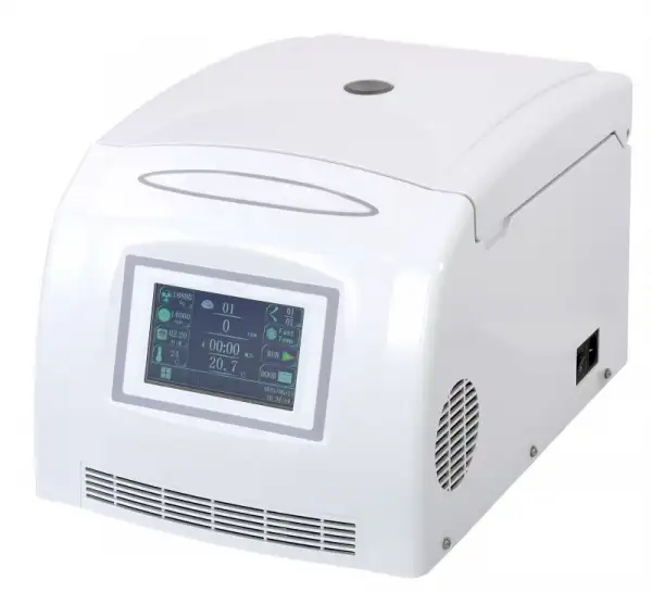
Micro Centrifuge BCMR-103
- Up to 3-Year Product Warranty
- US & EU Compliance Standards
- Door-to-Door Shipping
Technical Specifications
Detailed operating and construction parameters for this model.
| Model | BCMR-103 |
| Max. Capacity | 12 x 5 ml |
| Max. Speed | 15 000 rpm |
| Max. RCF | 21 630 Xg with 24 x 1.5/2.0 ml rotor |
| Control System | Microprocessor |
| Refrigeration System | CFC-Free |
| Drive System | Direct, induction motor drive |
| Display | Full color touchscreen interface |
| Rotor Identification | Auto-ID Instant, immediately upon rotor insertion |
| Programmability | via easy access touchscreen menu |
| Program Storage | 16 user-defined |
| Accel/Decel Profiles | 10/10 |
| Running Time | 1 s - 999 min : 59 s |
| Timer | Count up or down |
| Speed Accuracy | ± 10 r/min |
| Temp. Control Range | -10 °C to +35 °C |
| Temp. Accuracy | ± 1 °C |
| Noise Level | ≤ 58 dB(A) |
| Power Supply | AC 200-240 V, 50/60 Hz or AC 100-127 V, 50/60 Hz |
| Max. Power Consumption | 800 W |
| Dimension (W x D x H) | 11.2 x 15.7 x 11.2 in / 28.5 x 40 x 28.5 cm |
| Weight w/o Rotor | 46 lb / 21 kg |
Accessories For Purchase View compatible optional accessories and additional items available separately.
| Images | Name | Rotor Capacity (places x volume, ml) | Tube Size (Φ x L in mm) | Max Speed (rpm) | Max RCF (xg) |
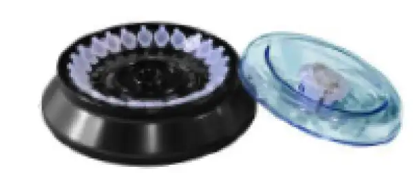 | No.1 Fixed-Angle Rotor | 24 x 1.5/2.0 ml (with adapters for 0.2/0.5 ml tube) | Φ11 x 42 | 15,000 | 21630 |
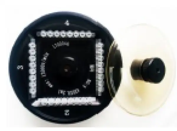 | No.2 Fixed-Angle Rotor | 4 x PCR-strips | - | 15,000 | 19620 |
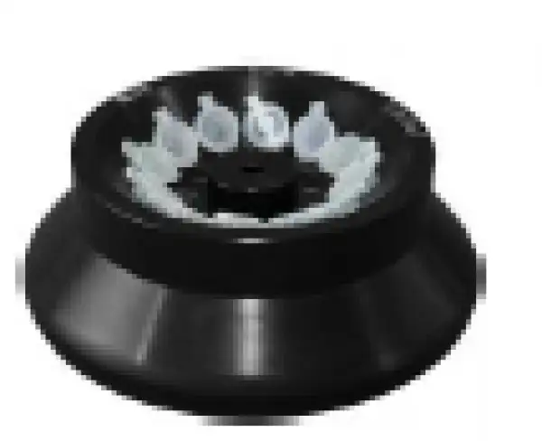 | No.3 Fixed-Angle Rotor | 12 x 5 ml | Φ14 x 54 | 15,000 | 20670 |
Operating Manual View instructions, operating procedures, safety information, and maintenance guidance.
1. Preface
2. Safety and cautions
2.1 Installation and maintenance cautions
2.2 Electric cautions
2.3 Fire prevention cautions
2.4 Operation cautions
2.5 Chemistry & Biology cautions
3. Symbols & its meanings
4. Product introduction
4.1. Working principle
4.2 Product features
4.3 Product use and application scope
4.4 Position of parts
5. Install & Debug
5.1 Installation requirements
5.2 Machine installation
5.3 Rotor installation
5.4 Loading Rotors
5.5 Close the lid
5.6 Connect the power
5.7 Debugging.
6. Operation
6.1 Basic operation steps
6.2 Operating system description
6.3 Set centrifugation parameters
6.4 Function menu explanation
1. Preface
In order to ensure safe operation of this centrifuge, please read through this instruction manual carefully and follow the instructions before use or maintain this centrifuge. Please paste the Operational Program (attached separately) at the working area.
The centrifuge should be operated by trained specialists only.
 Failure to follow this instruction and safety information in this instruction manual will result in the expiration of the seller's warranty.
2. Safety and cautions
Safety and Cautions: safety and cautions aim at the safety operation of the centrifuge which was described in this instruction. In the interest of your own personal safety, please read it carefully before you install, operate, maintain and repair this centrifuge. Knowing this safety caution and proper operating skills, the operator can avoid the hurting as well as avoid the damage to the centrifuge.
2.1 Installation and maintenance cautions
·The centrifugal chamber may contain rotors and other accessories in it, please open the lid to check and get out of it (if any) before installing. (If you order the machine with one rotor only, the rotor may already been installed onto the spindle properly).
·When maintaining this centrifuge, all the parts which needed to remove the cover may cause electric injury. Make sure you already cut off the electricity and pulled the plug from the socket before maintaining this instrument. The maintaining work should be done by professional staffs.
·Please use only rotors, accessories, replacement parts for this centrifuge which has been approved by us.
·A safety zone of at least 30 cm must be maintained around the centrifuge. People, dangerous substances or objects must be kept out of the safety zone during the centrifugation run.
2.2 Electric cautions
·To reduce the danger risk of the electric shocks, this centrifuge adopts three core plug which must be connected with three core socket which connects with earth wire.
·Make sure the socket on the wall connects well with the earth wire. Make sure the power voltage must conform to the voltage this centrifuge required.
·Do not use three-hole changing to two-hole expansion power adapter.
·Do not use two wire expansion socket or multi-use power adapter which is not connect with the earth wire.
· Do not put the container which is full of liquid on or near the centrifuge, because if the container is knocked over, the liquid may penetrate into the centrifuge, which would damage the components.
·The main plug must be freely accessible at all times. Pull out the power supply plug or disconnect the power supply in an emergency.
To avoid can't disconnect the mains from the centrifuge in the event of errors occurring in time, an emergency switch which is separate from the centrifuge must be available, this switch should be outside the room in which the centrifuge is operated or next to the exit of the room.
2.3 Fire prevention cautions
·Please use the same type specification overload insurance fuse. This machine use
the type specification for the fuse is LFT 10A L250V φ5x20.
·This centrifuge is not designed to separate flammable and explosive materials. Do not use this centrifuge to centrifuge these materials, do not put these kinds of materials in the centrifuge, or put such material in the safety zone.
2.4 Operation cautions
Do not start the centrifugation run before you cleaning the centrifuge chamber, otherwise damages might occur!
Always ensure the rotor has been securely fastened on the spindle, the samples have been balanced and the rotor lid (if equipped) has been screwed on the rotor tightly before each run.
Make sure the setpoint speed for the rotor you are going to run do not exceed its max speed allowed before each run.
· Do not start the centrifugation run when the lid is open.
· Never open the lid until the rotor has completely stop and this has been confirmed in the display.
· In case of fault or emergency release, disconnect the centrifuge from the mains first,
open the lid only during rotor standstill.
· Please do not lean on, lift up, or move the centrifuge before the rotor stop running.
· Do not stretch anything into the centrifuge when the rotor is running.
·When the centrifuge is running, according to EN / IEC 61010-2-020, no persons, dangerous substances or objects may be within the safety margin of 30 cm around the centrifuge. Please don't work in that range unless you need to debug the machine.
To avoid damage to the compressor, wait for at least 5 minutes after switch off the machine before switching on the machine again.
2.5 Chemistry & Biology cautions
·Routine operation may include all kinds of solution and test samples which may be pathogenic, toxic or radioactive material, all the materials should not be centrifuged by this centrifuge unless protective measures have been adopted.
·Please pay attention to the description of the solution on the original solution container before you are going to centrifuge it.
·Be careful when you holding the liquid because they are contagious.
·The operator should obey this instruction manual and method of the laboratory strictly when they operating this centrifuge.
·All the waste solution must be destroyed according to the safety and protection demand of the environment.
When you ask for after-sale service, please make sure you had cleaned up the centrifuge, thanks in advance for your support.
3. Symbols & its meanings
No. | CODE | GB No. | MEANING |
1 | ~ | 4706.1 | AC POWER |
2 | | 5465.2 | CONNECTED (MAIN POWER) |
3 | ○ | 5465.2 | DISCONNECTED (MAIN POWER) |
4 | | 4728.2 | PROTECTIVE GROUNDING |
5 | | 4793 | WARNING! |
6 | | 2894 | CAUTION ! |
7 | | 2894 | DANGER! |
8 | | 2894 | WATCH OUT FOR FIRE! |
9 | | 2894 | DANGER ELECTRIC SHOCK! |
10 | | 2894 | BEWARE OF BIOLOGICAL HAZARDS! |







Table 1
4. Product introduction
4.1. Working principle
The centrifuge is a instrument which use the powerful centrifugal force which was generated by the high speed running of the rotor to accelerate the settlement of particles in solution, to make the samples of different subsidence coefficient and different density of the substance to be separated, concrete and pure.
When operate a centrifuge, loading equivalent volume solutions into each centri-
fuge tubes / bottles which you are going to centrifuge and load these centrifuge tubes / bottles into the positions of the rotor symmetrically (the centrifuge tube / bottle must be opposite each other to make sure the rotor can run at a balance state).
The relative centrifugal force (RCF) depends on rotational radius " r " and rotational speed (revolutions per minute) " n ", its computational formula as following:
RCF=1.118x10⁻⁵xn2xr(xg)
Among the formula:
n -- rotational speed (r/min)
r -- rotational radius (cm)
G -- gravitational acceleration (9.8 newton/kg)
The required centrifugal time T for particle separation sediment in the mixture solution was counted as the following computational formula:

Figure 1
Among the formula:
ρ -- mixed solution density (g/cm³)
μ -- mixed solution viscosity (P)
n -- rotational speed (r/min)
r -- rotor rotational radius (cm)
σ -- particle density (g/cm³)
Rmax -- the horizontal distance from bottom surface of centrifuge solution to axis (cm)
Rmin -- the horizontal distance from solution surface to axis (cm)
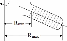
Figure 2 (fixed-angle rotor)
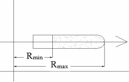
Figure 3 (swing-out rotor)
Our centrifuge is with automatic rpm / rcf conversion function, do not need to manual calculation.
4.2 Product features
This refrigerated microcentrifuge (hereinafter called centrifuge) adopts induction motor driving (brushless), microprocessor control, user-intuitive touchscreem interface, corrosion-resistant 304 stainless steel centrifuge chamber, motorized lid latch and other safety technologies for safe operation. It can store 1 000 programs and there are 40 acceleration rates and 40 deceleration rates available for daily use. Frequency converter compressor and CFC-free refrigerant are adopted for the refrigeration system, has both pre-cooling function and standby cooling function. The operation parameters such as the running speed/centrifugal force, centrifugation time can be modified during operation. The self trouble diagnosis system can detect speed, lid lock, motor failure and many other kinds of fault automatically and show the fault code. The electronic lock system security the centrifuge work safely. The centrifuge can't start when the lid does not lock. All the rotors listed can reach below 4 °C at full speed and -10 °C at low speed.
4.3 Product use and application scope
This centrifuge is widely used in the field of biochemistry, agricultural science, environmental protection, clinical medicine, pharmacy, inspection and quarantine, radio-immunity and other research & manufacturing fields. It is a ideal separation equipment for colleges/universities, research institutes, and enterprises.
4.4 Position of parts
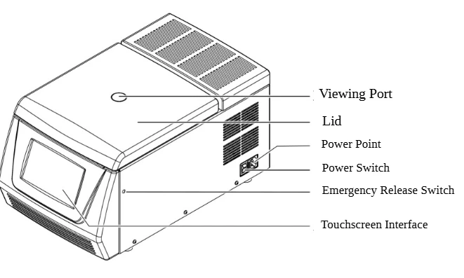
Figure 4
5. Install & Debug
5.1 Installation requirements
This centrifuge should be installed in the indoors, on a good, stable base, such as installed on a horizontal rigid solid laboratory worktable. No corrosive, conductive dust or damaging insulating air, and no powerful vibration source nearby, avoid direct sunlight.
To make sure the centrifuge can work properly, the install environment should fulfill the following conditions:
Environment temperature:5°C ~ 40°C
Relative humidity: ≤80%
Atmospheric pressure: 860hPa ~ 1060hPa
Supply voltage: AC 200 - 240V,50/60Hz
1. Space requirements
In order to ensure the in-out vent of cooling air the centrifuge demand, the set-up location must be well-ventilated at all times.
A safety zone of at least 30 cm must be maintained around the centrifuge. When the centrifuge is running, according to EN / IEC 61010-2-020, no persons, dangerous substances or objects may be within the safety margin of 30 cm around the centrifuge.
The dimensions of the centrifuge are shown in the diagram below:
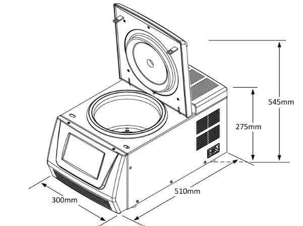
Figure 5
2. Power supply requirements
The power for this centrifuge is single-phase 200-240V, 50/60Hz, 10A. The power should have protective earth wire. Do not use null line to instead of protective earth wire. If you are not sure about the power you are using, please contact your distributor or local electricity board.
For ensure the good grounding of the centrifuge, this centrifuge connects with a single-phase three core plug. If the plug can not put into your socket, please contact electrician to change your original socket to ensure the safe action of the single-phase three core plug.
To avoid can't disconnect the main from the centrifuge in the event of errors occurring in time, an emergency switch which is separate from the centrifuge must be available, this switch should be outside the room in which the centrifuge is operated or next to the exit of the room.
5.2 Machine installation
Remove the package (by the user)
Users should check the package appearance when receiving the product. Severe impact, recumbency and upend etc. should not happen during transportation. The package appearance should be well. Please contact with the cargo agent and inform our company in time if any damage is discovered.
First, open the package, get out of the rotor and accessories; Second, get out of the centrifuge from the package and place the centrifuge in a stable and level manner in a suitable place, such as place in the reserved horizontal rigid solid laboratory worktable . During set-up, the required safety margin of 30 cm around the centrifuge is to be kept according to EN / IEC 61010-2-020. Last, properly deal with the package and packing, not to pollute the environment, or save these for possible future transport of the centrifuge.
Below is a schematic diagram of unpacking.
(1) Use scissors or knives to remove the packing belt and open the packaging box.
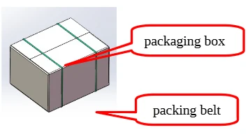
Figure 6
(2) Remove the upper foam.
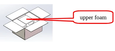
Figure 7
(3) Remove the foam on the right side, and take out the rotor, installation tool, power cord, and other accessories placed in the foam groove.
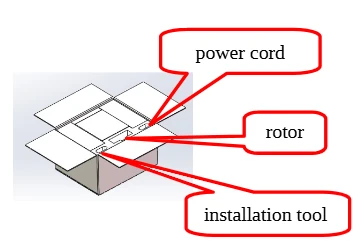
Figure 8
(4)Remove the foam on the left side.
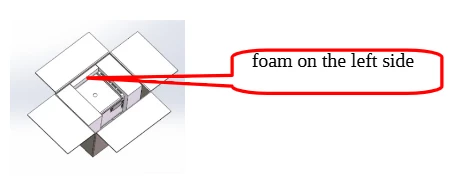
Figure 9
(5) Slowly move the centrifuge and then remove it along with the foam at the front and rear.
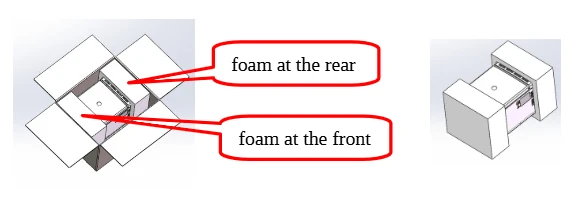
Figure 10
(6) Remove the front and rear foam covers, take out the centrifuge from the plastic bag, and be careful not to bump it.
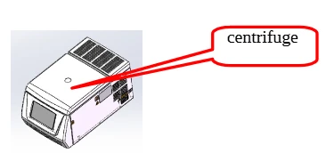
Figure 11
WARNING:
Never lift the centrifuge by the lid.
Always lift the centrifuge at the both sides on the bottom plate. Due to the net weight of this centrifuge is about 30kg, the centrifuge may need to be carried by two people. Avoid impact during the carry process, the centrifuge will be damaged by impacts.
After installation, the four rubber feet on the bottom of the centrifuge should afford uniform stress.
The horizontal leveling of the centrifuge must be checked every time after moving it to a different location.
After transportation, the centrifuge should be left to stand for at least 2 hours before connecting to the power supply!
5.3 Rotor installation
(1) Open the lid.
The lid can only be opened when the rotor is standstill.
There are two ways to open the lid:
1) Connect the centrifuge's plug to the power supply, switch on the power switch at the right side of the machine, then tap the icon "Door", after you hear a sound of unlock, lift up the lid.
2) Open the lid by using the emergency release switch.
Emergency release switch, there is a small hole on right side of the machine(with indicator label), use the 5 mm Allen key insert into it vertically and rotate it toward the anticlockwise then the lid can be open.
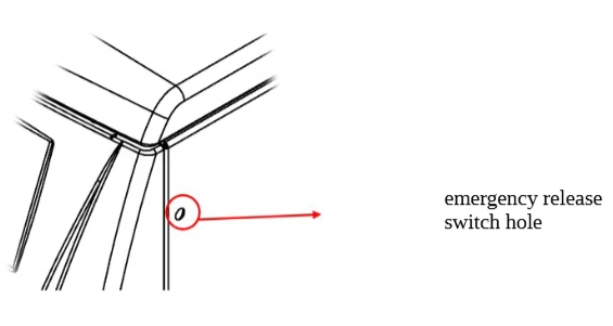
Figure 12
The emergency release switch should not be used at ordinary time, it can only be used when power failure or something is wrong with the lock.
Take out the rotor and accessaries from the centrifuge chamber (if any) after opened the lid.
(2) Installing the rotor.
First, align the center hole of the rotor with the motor spindle and place it vertically, so that the cylindrical pin is inserted into the rotor clamp slot (if it is not inserted, the nut cannot be tightened). Second, use the 5mm Allen key to pass through the inner hole of the rotor core and tighten the locking nut clockwise, then cover the rotor lid. For this refrigerated microcentrifuge, the rotor may already been installed onto the spindle before it been shipped out from factory if you ordered the centrifuge with one rotor only.
First step:
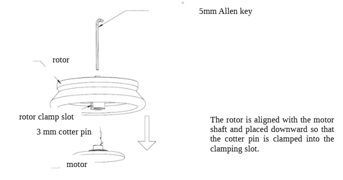
Figure 13
Second step: Tighten the compression nut clockwise with the Allen key, remove the Allen key, and the rotor installation is completed.
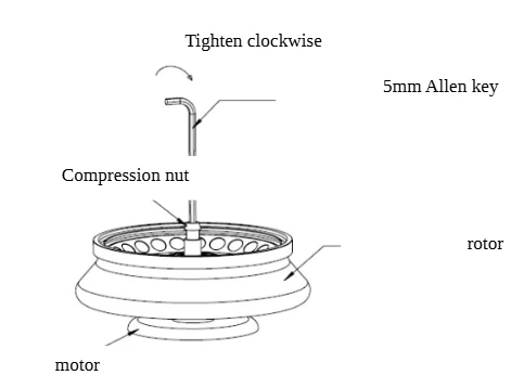
Figure 14
For safety, always ensure the rotor has been securely fastened on the spindle before each run.
Cover the rotor lid before each run.
(3) Discharge the rotor.
Use the 5mm Allen key to loosen the locking nut on the rotor counterclockwise (about 8 turns), and then lift the rotor upwards to complete the discharge.
5.4 Loading Rotors
Always balance the samples.
Push the button or screw to take down the rotor lid (if rotor lid is equipped).
To ensure safe operation of the centrifuge, the rotor must be evenly loaded at all times. The centrifuge tubes / bottles must be filled with same volume solutions, the loaded centrifuge tubes / bottles must be opposite each other, the weight difference of the loaded tube racks / buckets (for swing-out rotor) should not exceed 1 g. Imbalanced running is strictly prohibited. There is serious accident will occur due to the imbalanced running.
Please check the maximum permissible revolutions of the test tubes / bottles (producer indication) .
For the fixed-angle rotor, the loaded test solution for each tube / bottle should not exceed 75% of its nominal capacity as usual unless you can make sure the test tube / bottle can be 100% sealed. The test tubes / bottles must be loaded with equal weight solutions and must be loaded into the rotor symmetrically to make sure the rotor can run at a balance state.
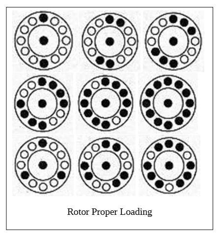
Figure 15
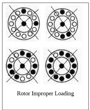
Figure 16
5.5 Close the lid
Cover the rotor lid if the rotor lid was equipped (some of the fixed-angle rotors equipped with a lid) after the tubes / bottles were well placed, then press the lid down, the lid was locked after you heard a sound.
For this refrigerated microcentrifuge, servo motor was adopted for lid open & lid lock. After switched on the machine, tap the icon "Door", the lid will be unlock and you can open the lid. When you need to close the lid, close the lid gently, the lid will be lock automatically.
If the machine did not switch on, the lid can't be lock due to the lid adopt a servo motor for lid open & lid lock.
Do not put your fingers between lid and the housing.
Do not bang the lid shut.
5.6 Connect the power
Make sure the power connected with an earth wire before you connect the machine to the power, then switch on the power switch.
5.7 Debugging.
WARNING: Do not start the centrifugation run before you cleaning the centrifuge chamber, otherwise damages might occur!
Operate the centrifuge like the operation sequence No.6 described below, first choose low speed running(2000 rpm), then increase 2000 rpm gradually to the highest speed, if there is no exception, the debugging is successful.
6. Operation
6.1 Basic operation steps
Before operating the centrifuge, you need to understand the type of rotor being used, the required speed/centrifugal force, runtime, and operating temperature. For detailed parameter settings, refer to Section 6.3. The basic operation process of the centrifuge is as follows:
(1) Connect the power supply and turn the power switch to ( | ), which will illuminate the display screen.
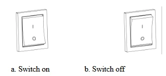
Figure 17
(2) Tap the icon "DOOR" to open the lid and lift it up.
(3) Select the appropriate rotor.Loading rotors to complete sample loading, then close the lid.
(4) Set the operational parameters: select the rotor model (automatic recognition models do not require manual setting), and set the speed/centrifugal force, temperature, runtime, acceleration rates and deceleration rates. For detailed operations, refer to Section 6.3 Set Centrifugation Parameters.
(5) Tap the icon "RUN" to begin the centrifugation run.
(6) Wait for the time to end or tap the icon "STOP" to end the run;
(7) Once the rotor has completely stopped and a prompt sound is heard, tap the icon "DOOR" to open the lid. After hearing the unlocking sound, lift the lid, take out the samples, and clean the chamber.
(8) After use, switch off the centrifuge power.
6.2 Operating system description
This centrifuge adopted graphic user-intuitive touchscreen interface. The home screen shows as below.
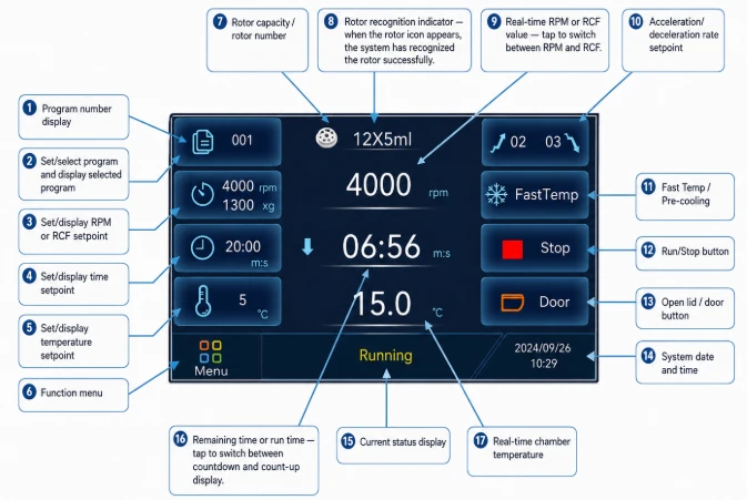
Figure18
More explanation about the icon in the home screen
1)  Program group: Display the program group number and name being called, with the temporary program group "000" displayed by default; Tap the icon to enter the program group interface, where you can view, modify, and call program groups.
2)  FastTemp: Tap this icon will cause the system to run at 5000rpm and cool at maximum power. When the temperature in the centrifuge chamber reaches the set temperature, the rotor will automatically stop running and prompt. (Please confirm that the rotor is installed before starting this function!)
3)  Stop/Run: Tap to start/stop running. Tap the icon "
  Run" to start running, and the icon will change to "
  Stop" during runtime. Tap the icon to " Stop" to terminate the running.
Long press icon " Start" to start short run centrifugation, and the system will run to the set speed at the maximum rate; Stop the running after releasing the icon. The maximum short run time is 2 minutes.
4)  Indicate the status of the lid. The icon
  indicating that the lis is in the closed state. Tap the icon in this state can unlock the lid. The icon
indicates that the lid is in the open state and cannot start the run when the lid is open.
5)  Display the running time. Tap to switch the time display mode to count down timing, or count up timing, or continuous centrifugation timing. The upward arrow
  indicates count up timing and displays the running time. The downward arrow
  indicates a countdown timming and displays the remaining running time. The symbolꝎ indicats continuous centrifugation, the centrifuge will continue to run until the timing limit (99h59m59s), and the timing mode is count up timing.the timing mode is count up timing. During operation, the display mode can be switched, but it c annot be switched to continuous centrifugation.Continuous centrifugation can be switched in the shutdown state.
6.3 Set centrifugation parameters
(1) Set Speed / RCF value
Tap the rotation speed/centrifugal force icon on the left side of the main interface to access to the speed/RCF set interface, then enter the desire speed value or RCF value on the keypad directly, tap "OK" to save the setting. According to the current installed rotor, the set speed value will be converted to centrifugal force automatically and displayed (The centrifugal force will also be automatically converted to rotational speed when setting centrifugal force, thus just set the speed or set the RCF is ok). If the speed set point or centrifugal force setpint is greater than the upper limit of the rotor installed, the set value cannot be saved.
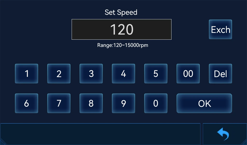
Figure 19
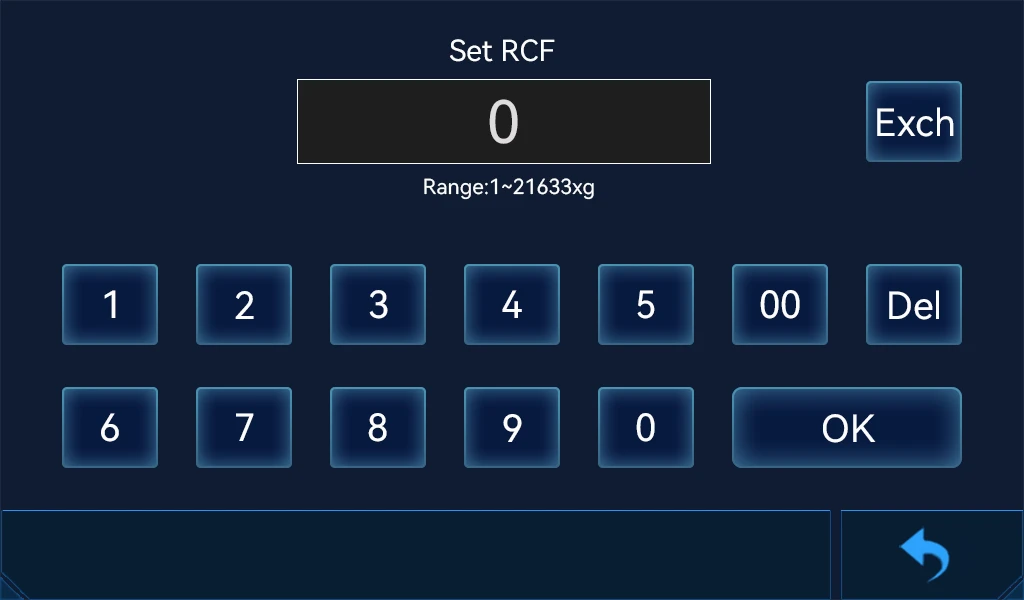
Figure 20 (speed / rcf set interface)
Interface Description:
 Tap it to switch the current settings between the speed setting and the centrifugal force setting.
 Delete key. Tap to delete the entered numerical value.
 Confirm key. Tap to save the current set value.
 Back key. Tap to back to the previous level.
Tap to switch the current settings between the speed setting and the centrifugal force setting. Enter the desired numerical value on the keypad directly, Tap to confirm the settings. Tap to back to the previous page.
(2) Set run time
Tap the icon  on the home screen to access to the time set interface then enter the desire time value on the keypad directly, tap "OK" to save the setting. If the time setpoint is greater than or equal to 1 hour, the timer in the home interface will automatically display hours : minutes; if the time setpoint is less than 1 hour, the timer in the home interface will automatically display minutes : seconds.
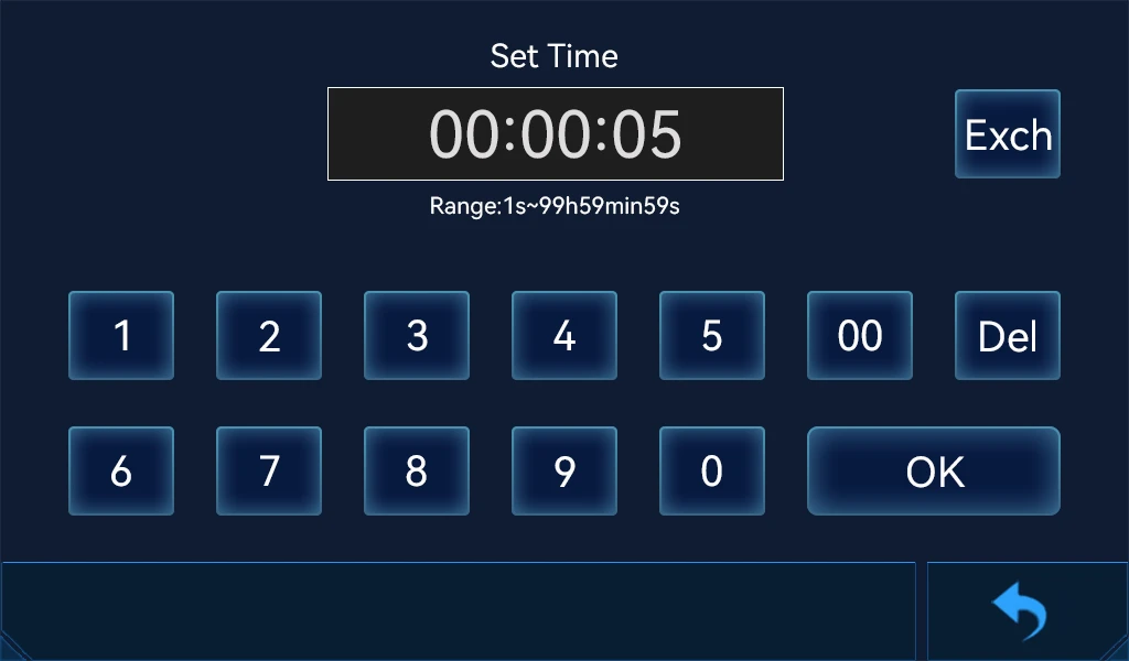
Figure 21
Interface Description:
 Tap it to switch the temperature value to either above zero or below zero.
Delete key. Tap to delete the entered numerical value.
Confirm key. Tap to save the current set value.
Back key. Tap to back to the previous level.
(4) Set acceleration and deceleration rates
Tap the icon  on the home screen to access to the acceleration and deceleration rates set interface then enter the desire acceleration and deceleration on the keypad directly, tap "OK" to save the setting. The acceleration and deceleration set range is 1 to 40, 1 is fastest, 40 is the slowest(the declaration rate 40 is unbraked deceleration). The acceleration and deceleration rates time are varies according to the different capacity rotor, the larger the capacity of the rotor the acceleration and deceleration time will be longer, the smaller the rotor capacity is the faster the acceleration and deceleration.
Tap the key to switch between acceleration and deceleration rates settings. Enter numbers by using the numeric keypad and tap the icon to confirm thesettings, or tap the back key to cancel the setting and back to the previous level.
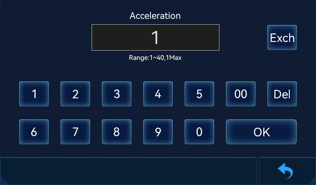
Figure 22 (acc/dec set interface)
(5) user-defined programs
For user convenience, this centrifuge can store 1 000 programs, including the 999 user-defined programs numbered from 001 to 999 and 1 temporary program numbered 000. After modify the parameters of the program which called from the stored program group on the home screen, the modified parameters are automatically stored as the temporary program No. 000, and the parameters of the original program will not be modified. If you want to modify the parameters of the original program, please enter into the program group interface to modify it.
The preset program group has stored initialization data at the factory, users can modify it by themselves.
1) Tap the icon  on the home screen to access to the program group interface. You can choose program or edit program parameters after enter into the program group interface. Tap the program number can call the program to the home screen. Tap any parameter of a program to enter the edit interface then can modify the parameter.
2) After modify the parameters of the program called from the stored program group on the home screen, the modified parameters are automatically stored as the temporary program No. 000, and the parameters of the original program will not be modified. If you want to modify the parameters of the original program, please enter into the program group interface to modify it.
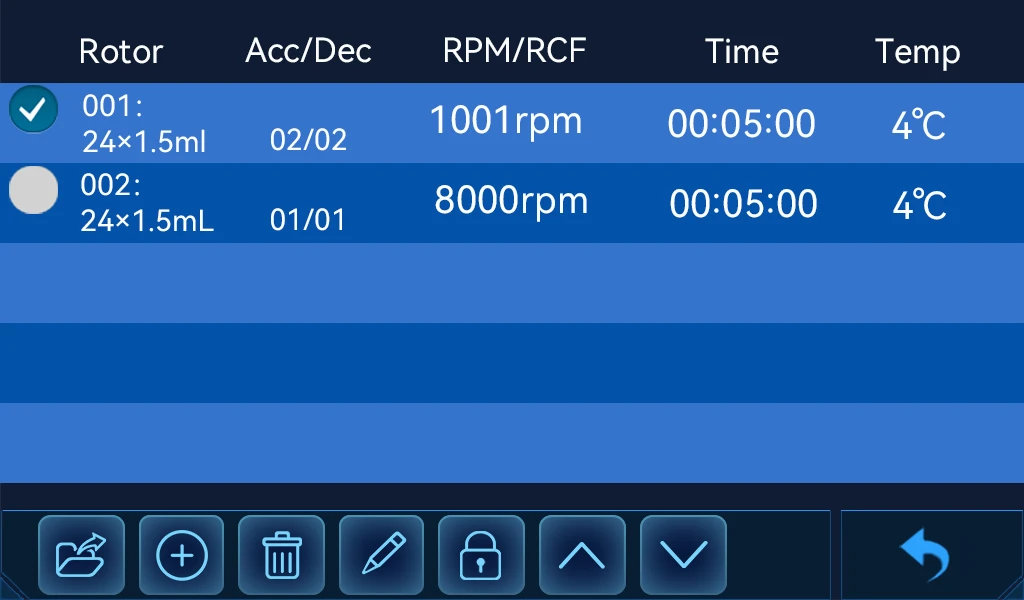
Figure 23 (program group set interface)
Program group setting instructions:
1). Call a program group
After selecting the program group, tap the icon  to call this program group. If a temporary program group needs to be returned after calling, it can be achieved by modifying parameters on the main interface.
2). Add a program group
Tap the icon  to add a new program group and set the program group parameters in the pop-up window. The program name can be entered with 1-15 characters, including uppercase and lowercase letters, numbers, and regular symbols.
3). Delete a program group
After selecting the program group, tap the icon  to delete the program.
4). Modify a program group
After selecting the program group, tap the icon  to modify the program group notes and parameters.
5). Lock/Unlock Program Group
After selecting the program group, tap the icon  to lock the program or tap the icon
  to unlock the program group. The locked program group requires setting a password. The locked program group cannot be modified or deleted.
6.4 Function menu explanation
Tap the function menu icon  on the home screen to access to the function menu interface. On this interface, you can modify the user's permissions and passwords, adjust system settings, view device information, etc.
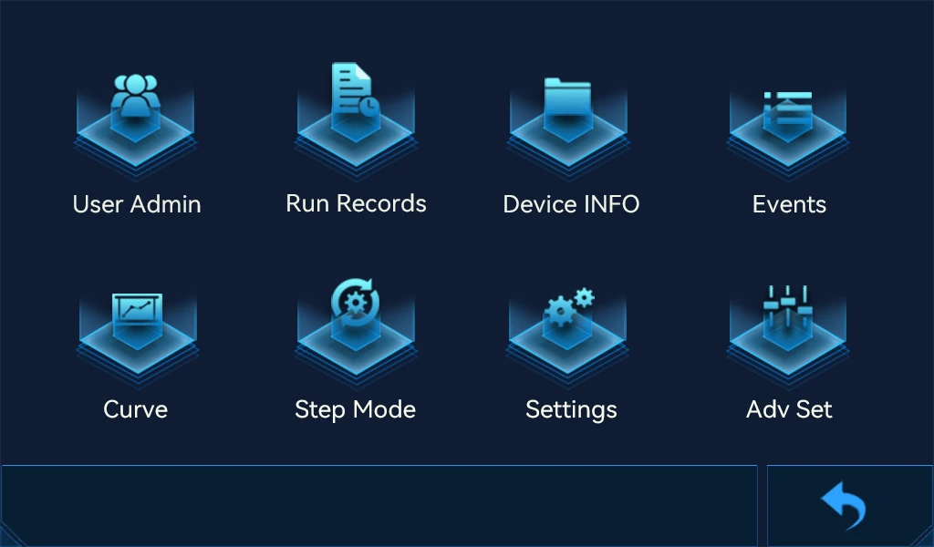
Figure 24 ( function menu interface)
Function icon explanation
1) User Administration
Tap the user administration icon to enter into the user administration interface where you can set user account passwords, operation permissions, etc.
The system is divided into three levels of permissions: administrator, technician, and operator.
The default administrator account for the system is 001, the username is Administrator, the password is 1111. You can modify the username and password of this account.
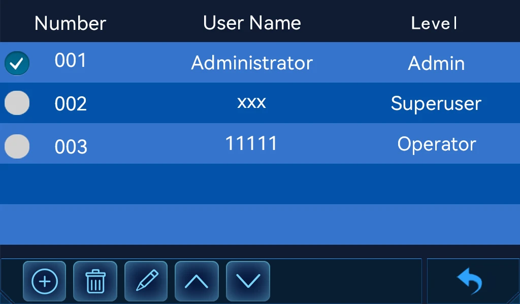
Figure 25 (user management interface)
Setting Instructions:
1. Add new user
Tap the icon  to add a new user. The username length is 1-15 characters, and the password length is 4-9 characters. The username cannot be duplicated.
2. Delete user
Select the account and tap the icon  to delete the user.
3. Modify user
Select the user and tap the icon  to modify the username, password, or permissions.
2) Run history
Tap the icon "Run Records" to enter into the page, then you can view the historical usage records. The system only records complete operational data, including the rotor information used, run speed, run time, acceleration rates, deceleration rates, temperature, and system time during the operation. Up to 1000 records can be recorded, and if exceeded, it will automatically overwrite from the first record onwards.
3) Device information
Tap the icon "Device INFO" to enter into the page. You can check the main unit information, current installed rotor information, and all rotor types that can be matched with this model, including the rotor type, parameters, production date, rotor radius, and remaining usage times.
4) Events
Tap the icon "Events" to enter into the page. You can view the system operation records, including recording time, operating user, event ID, and event details.
5) Curve
Tap the icon "Curve" to enter into the page. You can view the real time curve graph of the current device's run speed, centrifugal force, temperature, and vibration over time. This function records data and draws a graph from the moment the host is turned on.
6) Step mode
Tap the icon "Step mode" to enter into the centrifugal mode interface. The centrifugation mode can be switched to regular centrifugation or multi-stage centrifugation, and the multi-stage centrifugation parameters can be edited.
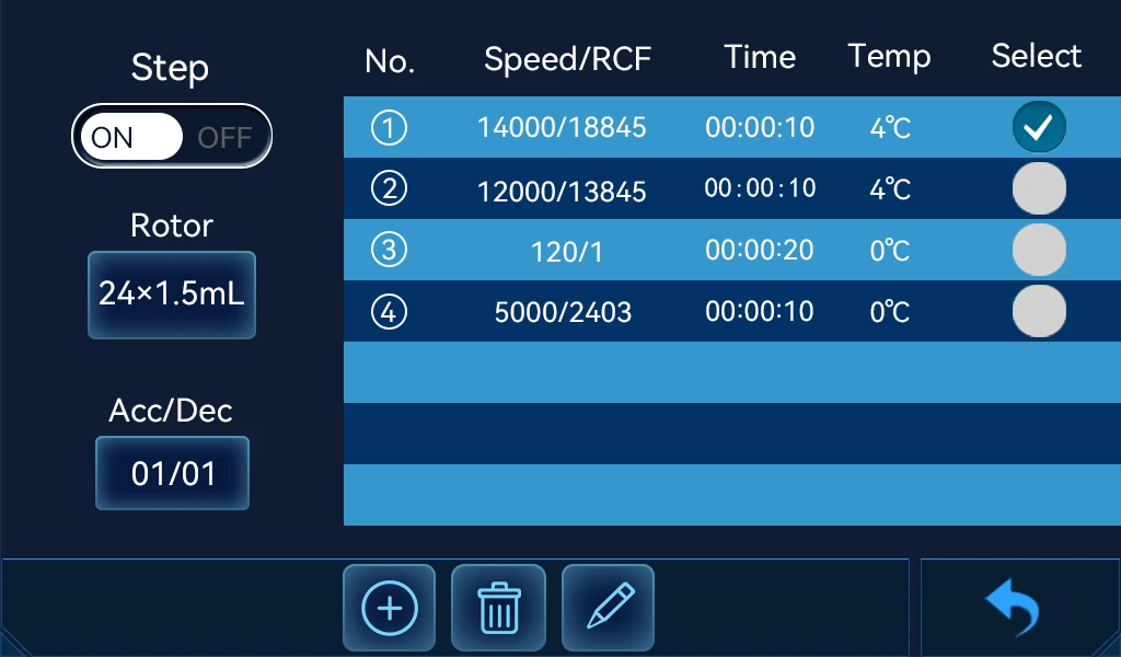
Figure 26 (centrifugal mode interface)
Centrifugal mode setting instructions:
1 .General mode
Set the centrifugation parameters normally, stop centrifugation after the running time is over, and the parameters will not change midway. Switch the button to  , which indicating that it is general mode.
2. Multi-stage mode
According to the running time set for each centrifugal stage, the system automatically adjusts the speed and temperature according to the parameters of the next centrifugal stage after the time is reached, without stopping or requiring personnel operation. This system can set up to 7 centrifugal stages.In multi-stage centrifugal mode, parameters cannot be modified from the main interface, and modifications must be made by entering the centrifugal mode interface.
Switch the button to  , indicating that it is currently in multi-stage centrifugal mode.
This system can set up to 7 centrifugal stages. The parameter setting method is as follows:
1. Add centrifugal segments
Tap the icon  and set the parameters for adding a centrifugal segment in the pop-up window.
2. Modify parameters
Select the centrifugal segment to be modified, tap the icon  and modify the corresponding parameters in the pop-up window.
3. Delete centrifugal segments
Select the centrifugal segment to be deleted, tap the icon  to delete it.
4. General parameter settings
Tap the icon  to select the rotor model to be used, this setting is suitable for all centrifugal segments.
Tap the icon  to set the accelerate rates and decelerate rates, this setting is suitable for all centrifugal segments.
7) System setting
Tap the icon "  " to enter the system settings.. It can set the system sound, touch screen sound, users login, timing mode, cooling system, temperature control mode, imbalance detection sensitivity, and lock screen time. The icon
  indicates the option is on. The icon
  means the option is off.
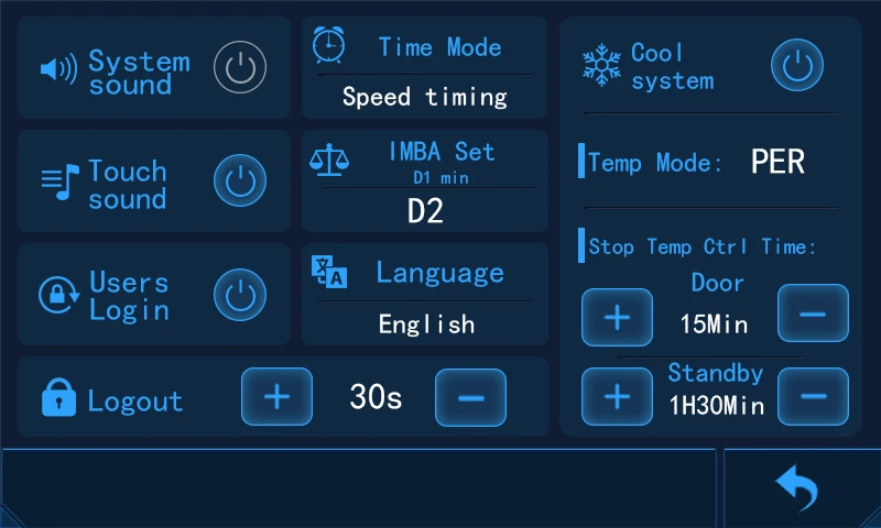
Figure 27 (System setting interface)
Setting Instructions:
1. System sound
Turn on or off the system sound.
2. Touch sound
Turn on or off the touch sound.
3. Users Login
Enable or disable user login function. Enter username and password to enter the system after enabling it.
4.. Logout
Tap the icon  to activate the automatic logout function and adjust the logout time in increments of 30 seconds. The system automatically locks the screen after n seconds of operation.
5. Time mode
Tap to switch between the two timing modes. The "speed timing" means the timer count down after the speed setpoint reaches. The 'Run timing' means the system immediately starting timing after tapping the icon "Run".
6. IMBA set(imbalance sensitivity set)
Tap to set the imbalance level. There are 4 levels in total, the D1 has the highest sensitivity. The higher the sensitivity, the lower the system's tolerance for imbalance.
7. Language
Tap to switch the system language between Chinese and English.
8. Cool system
Turn on or turn off the refrigeration system.
The following settings will only be effective when the cool system turned on:
Temperature control mode: Switch between two temperature control modes. "Economy" means energy-saving mode, while "performance" means keep to operate at its optimal state.
Stop temperature control time: The machine can be set to automatically stop cooling after a certain interval in