Get Price
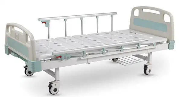
Manual Hospital Bed BHBD-509
- Up to 3-Year Product Warranty
- US & EU Compliance Standards
- Door-to-Door Shipping
Technical Specifications
Detailed operating and construction parameters for this model.
| Model | BHBD-509 |
| Material | Powder coated steel bed frame, top class ABS & PP plastic |
| Overall dimension | 2080 mm (L) * 980 mm (W) * 470 mm (H) |
| Bed board dimension | 1910 mm (L) * 830 mm (W) |
| Functions | Two functions controlled by cranks |
| Backrest | 0 - 75° |
| Knee gatch | 0 - 45° |
| Height (bed board to ground) | 470 mm |
| Protective railings | Collapsible 5-column aluminum protective railings, easy to grasp |
| Head & foot boards | PP head & foot boards, integrally blow-molded, easy to detach and clean |
| Castors | 360° swivel castors (Dia. 125 mm) with individual brakes |
| Optional feature | Shoe rack under bed board (optional) |
| Net weight | 65 KG |
| Standard accessory | I.V. Pole |
Product Features
Key design, performance, usability, and safety advantages.


Operating Manual View instructions, operating procedures, safety information, and maintenance guidance.
1. Precautions for Safe Use and Notices
2. Main properties and characteristics
3. Structure Description
4 Technical Specifications
5. Installation instructions
5.1 Installation method s of bed frames and castors
5.2. Installation of castors
5.3 Install the round steel frame
5.4 Installation of head & foot board
5.5 Installation of side rail
5.6 Installation of I.V. Pole and shoe rack, Medicine bag hook.
6. Operation Instructions
6.1 Operation for the crank
6.3 Lifting method of the side rail
7.Cleaning ,maintenance and storage
8.Common Faults and exclusion
9.Quality assurance and after-sales service
1. Precautions for Safe Use and Notices
Read this Warning notice carefully before operating.
We are not responsible for the bad results caused by improper operation by the user.

■DO NOT put your head/hand/leg/foot or other parts into the gap between side rail & head/foot board or finger into the bed during movements to avoid injure
Pay attention to the patient who can not control themselves

Figure 1
■Make sure the bed's bed board in flat position when only patient lying on the bed and no nursing person standing by
■Make sure the bed in lowest position when only patient lying on it and no nursing person standing by
■Children or the person who do not know how to operation are not allow to operate it
■DO NOT adjust the bed when patient lying on the bed with face down which may cause:

Figure 2
■Lying on the bed at the correct direction

Figure 3
■ DO NOT put your hand, fingers or foot into the gap under the bedboard

Figure 4
■DO NOT climbing ,playing, or jumping on this bed, also do not standing on this bed without support .Take care of your children

Figure 5
The bed in this page is a schematic bed
■DO NOT stay under the bed ,DO NOT put your hand or foot under the bed

Figure 6
■ DO NOT repair or modification without our support

Figure 7
■DO NOT sit on the back board when it's going up

Figure 8
■ DO NOT sit on the side rail or on the head&foot panel

Figure 9
■Keep away
from the fire and high temperature objects. Keep away from the environment of flammable gas and air mixture or with oxygen, or a mixture of nitric oxide

Figure 10
■DO NOT use other item to this bed for assembly use
■Bed without making electromagnetic compatibility test.ICU use is not recommended
■Keep the castor in brake position when bed fixed ;Release the brake before move the bed .
■Make sure the side rail pull up to the correct position and locked when patient lying on the bed
The bed in this page is a schematic bed.
2. Main properties and characteristics
Steel structure supply a safety and stable support. Powder coated bed board w ith ventilated
holes ,to avoid bedsore. Detach able PP head&foot board ,looks decent and easy for cleaning .
Collapsible protective railing in Aluminum alloy material, supply safety protection for the patient
lying on the bed . 4pcs high abrasion swivel wheels , Φ 125mm individual brake , let user to stop the bed easily. 2 pcs flexible crank ,to adjust the back rest and leg rest, change the bed position to make the patient feels comfortable
Back rest lifting angle: 0-75° ±5° Leg rest lifting angle: 0-45° ±5°
This bed suitable for all kinds of hospitals, medical care organizations, nursing homes ,family
nursing places and similar occasions ,used for examination, diagnosis, nursing, rehabilitation, etc.
3. Structure Description

Figure 11
(1) Head Board (2) Bac k part of the bedboard (3) Side rail (4) Switch for side rail
(5) Leg part of the bed board (6) Foot board (7) Crank for back rest (8) Crank for leg rest
(9)Bed leg (10) Castor (11) Shoe rack (12) Medicine bag hook (13) Bed structure
4 Technical Specifications
Main material: | Steel structure,top class plastic material ABS&PP Aluminum alloy side rail,Steel bed board with powder coated |
Overall size | 2080mm(L)x980mm(w)(±5mm ) |
Bed board dimension | 1910mmx830mm(±5mm ) |
Height from ground to board | 470mm(±5mm ) |
Castor | Diameter 125mm,Each four castor with separate brake. |
Net weight | 65KG |
Max load | 240KG |
Back-rest lifting | Angle | 0-75°±5° |
Knee-rest lifting | Angle | 0-45°±5° |
Environment | Professional medical institutions or similar places |
Security classification | I level |
Table 1
5. Installation instructions
Please check all the parts once you open the carton ,in case of any shortage of the below parts ,contact us or the distributor
NO. | Part | Qty | Pic | NO. | Part | Qty | Pic | |
1 | Bed main structure | 1set | | 6 | Castor | 4个 | | |
2 | Bed support | 2pcs | | 7 | Shoe rack | 1个 | | |
3 | Head&foot board | 1pair | | 8 | I.V.Pole | 1个 | | |
4 | Medicine bag hook | 1pc | | 9 | Round steel frame | 1个 | | |
5 | Crank | 2pcs |
| 10 | Side rail | 1pair | |


Table 2
5.1 Installation method s of bed frames and castors

Figure 12
Installation steps
Lean the bed tripod assembly against the support part of the chassis, and use a rubber hammer to strike the cross tube to assemble it onto the chassis, making sure the holes are aligned. Fix it with M8*50 hexagon socket head bolts.
5.2. Installation of castors

Figure 13
Installation steps
(1)Press the brake button of the casters to brake them.
(2) Insert the casters vertically into the flange nuts at the end of the bed foot frame assembly
(3) Then tighten it clockwise.
5.3 Install the round steel frame
Pass the round steel frame through the holes at the rear of the leg bed panel, and place a 6mm
flat washer at the bo ttom and fix it with M6 hexagonal lock nuts.
Press the brake button of the casters to brake them.")
Figure 14
5.4 Installation of head & foot board
Press the brake button of the casters to brake them.")
Press the brake button of the casters to brake them.")
Press the brake button of the casters to brake them.")
Press the brake button of the casters to brake them.")
Press the brake button of the casters to brake them.")
Figure 15
Insert the hook seat on the headboard into the fixed pins of the headboard at both ends of the welded assembly of the bed frame. The hooks will lock and fix the tailboard of the headboard.
Note: The tall one is the headboard and the short one is the footboard.After installation, please make sure to lock and fix the lock switch of the headboard and tailboard to prevent them from falling and causing injury.
5.5 Installation of side rail
Press the brake button of the casters to brake them.")
Figure 16
M8*60 hexagon socket bolt 4pcs
8-diameter flat gasket 4 pcs
M8 hexagonal lock nut 4pcs
5.6 Installation of I.V. Pole and shoe rack, Medicine bag hook.
Press the brake button of the casters to brake them.")
Figure 17
Hook the hooks on the shoe rack onto the bed frame.
Hook the medicine bag hook onto the bed frame.
Press the brake button of the casters to brake them.")
Figure 1
Insert the I.v. pole into the rack hole.
6. Operation Instructions
6.1 Operation for the crank
Function description of the joystick:
Press the brake button of the casters to brake them.")
Figure 18
(1) for back rest movement
(2) for leg rest movement
Back tilt (Angle 0-75° ±5°)
 for back rest movement")
Turn the lead screw at the back (No. 1) clockwise, and then the bed board at the head of the bed
Start to tilt and raise, with an inclination Angle of 0-75 ±5°, and can stay at any Angle within
the inclination range.
Turn the back lead screw (No. 1) counterclockwise, and the back bed plate will gradually lower from the inclined position, which can be at the inclination Angle
Stay at any Angle within the range until it is flat.
 for back rest movement")
Figure 19
Leg tilt (Angle 0-45° ±5°)
 for back rest movement") Turn the leg lead screw (No. 2) clockwise, and the leg bed plate will start to tilt and rise. The tilt Angle is 0-45° ±5°, and it can stay at any Angle within the tilt
Turn the leg lead screw (No. 2) clockwise, and the leg bed plate will start to tilt and rise. The tilt Angle is 0-45° ±5°, and it can stay at any Angle within the tilt
Turn the leg lead screw (No.2) counterclockwise, and the leg bed plate will gradually lower from the inclined position. It can stay at any Angle within the inclination range until it is flat.
Note: When the hand crank is not in use, it can be folded and hidd en under the rear bed board to prevent pedestrians
from getting injured.
 for back rest movement")
Figure 20
ON: Brake on, braking state
 for back rest movement")
Figure 21
OFF brake off, the state of releasing the brake
6.3 Lifting method of the side rail
If you need to raise the side rail, you should lift up it to the highest positing then it will lock automatically.
If you need to lower the side rail,you should pull up the switch of it, then you c an put down
the side rail.

Figure 22
7.Cleaning ,maintenance and storage
General cleaning for the bed , head&foot board and side rail
Clean with soft cloth which dip with diluted neutral detergent ,then clean off the diluted neutral detergent by cloth with clean water , finally, wipe it with dry cloth.
※Do not use volatile items (diluents, volatile agents, gasoline)
※Not available for high temperature
※Do not spill liquid to the bed
Please select low temperature sterilization method
■Preventive safety inspection and maintenance
Preventive safety inspection and maintenance only allowed for Professionals
Check stuck situation, loose fasteners and any presence of safety risks.
Add lube to the moving parts to assure smooth working
Inspection and maintenance intervals for 1 year
■Storage
Avoid store it in extreme cold,heat,dust or humidity environment
Optimum temperature in - 10°C to 40°C, relative humidity less than 80% RH, atmospheric pressure range: 760 hpa ~ 1060 hpa.
No corrosive gas, well-ventilated room.
Adjust the bed to zero position .do not put staff on the bed, especially heavy staff
8.Common Faults and exclusion
■Check if below common faults exist before you fix the bed
■If still do not work, contact us for support .DO NOT repair it without our support .
■We are not responsible for the bad results caused by improper operation by the user.
Common Faults | Cause of the faults | Exclusion |
Bed board not flat | Back-rest and leg-rest not operated to the required position | See the Operation for Crank |
Noise when bed being operated | Over load | Check if the bed working on over load |
Object stuck in the bed or joint parts stuck | Make sure the noise source ,remove the stuck objects , add some lubricating oil to make the joints part works smoothly | |
Bed can not be moved | Wheel on brake position | Release the brake of the castor |
Table 3
9.Quality assurance and after-sales service
■Please operate the bed following the user manual and the instruction label
Call us for technical support if quality problem
We supply a warranty for 1 year
■NO Free warranty service for situation below:
(1) Failure and damage caused by unauthorized dismantling and repair
&improper operation by the user
(2) Failure and damage caused by misassembling ,delivery & moving
(3) Failure and damage caused by earthquake, fire, smoke, abnormal voltage, lightning, flood and other natural disasters .