
Get Price
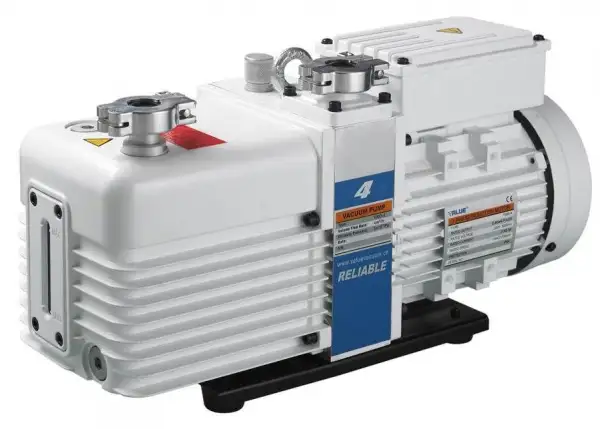
Liquid Suction Vacuum Pump BVAP-301
- Low noise, high efficiency:
- 1. Two-stage vacuum pump control technology with lower noise, higher vacuum, higher pumping efficiency, for the vacuum drying time is around 2-4 mins.
- Clean and reliable:
- 1. Double anti-return oil structure to more reliably protect the vacuum system from oil pollution after shutdown.
- 2. It adopts imported German oil seal and seals with fluororubber material to improve corrosion
- resistance and prevent oil leakage.
- 3. Adopting the aviation technology bushing treatment process, the life of the exhaust valve piece reaches 10 billion times.
- 4. It adopts high-quality materials such as vacuum pump oil imported from Japan, which makes the operation more reliable and has a longer service life.
- Up to 3-Year Product Warranty
- US & EU Compliance Standards
- Door-to-Door Shipping
Technical Specifications
Detailed operating and construction parameters for this model.
| Model | BVAP-301 |
| Displacement speed (50Hz m3/h(L/s)) | 4(1.1) |
| Displacement speed (60Hz m3/h(L/s)) | 4.8(1.3) |
| Ultimate partial pressure gas ballast close | 5x10 - 2Pa |
| Ultimate total pressure gas ballast close | 5x10 - 1Pa |
| Ultimate total pressure gas ballast open | 10 Pa |
| Power supply | Single/Three-Ph |
| Power rating | 0.4/0.37kW |
| Level of protection | IP44 |
| Intake and exhaust | KF16/25 |
| Oil capacity | 0.6 - 1.0 L |
| Motor speed (50/60Hz) | 1440/1720 rpm |
| Ambient temperature | 10 - 40°C |
| Noise level (50Hz) | ≤ 52dB |
| Weight | 19 kg |
| Dimension (LxWxH) mm | 440x144x217 |
Product Features
Key design, performance, usability, and safety advantages.
Low noise, high efficiency:
1. Two-stage vacuum pump control technology with lower noise, higher vacuum, higher pumping efficiency, for the vacuum drying time is around 2-4 mins.
Clean and reliable:
1. Double anti-return oil structure to more reliably protect the vacuum system from oil pollution after shutdown.
2. It adopts imported German oil seal and seals with fluororubber material to improve corrosion
resistance and prevent oil leakage.
3. Adopting the aviation technology bushing treatment process, the life of the exhaust valve piece reaches 10 billion times.
4. It adopts high-quality materials such as vacuum pump oil imported from Japan, which makes the operation more reliable and has a longer service life.
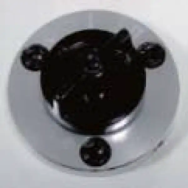
Gas ballast
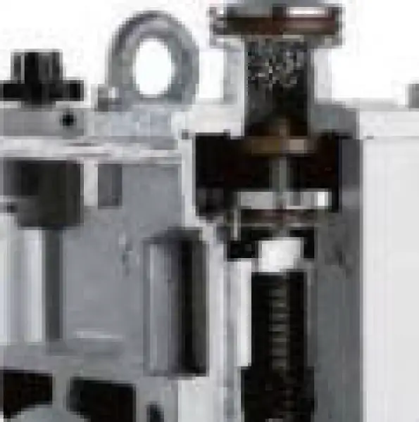
Auto antisuck back valve
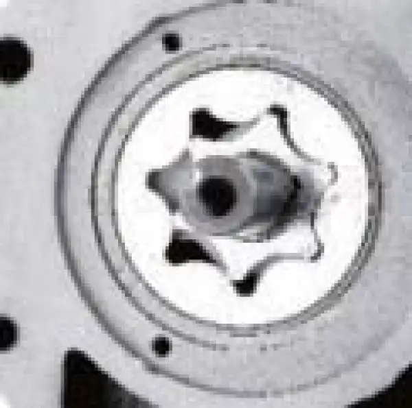
Gear pump
Integrated pump body structure
Extra Information View additional product guidance, technical notes, diagrams, and supporting information.
Capacity(L) | Degree of vacuum | model | Type | Flow of Vacuum pump | Time |
24 | 133Pa | VRD8 | two-stage pump | 2L/S | 1min |
51 | 133Pa | VRD8 | two-stage pump | 2L/S | 1min |
91 | 133Pa | VRD16 | two-stage pump | 4L/S | 2min |
125 | 133Pa | VRD16 | two-stage pump | 4L/S | 3min |
216 | 133Pa | VRD24 | two-stage pump | 6L/S | 4min |
Operating Manual View instructions, operating procedures, safety information, and maintenance guidance.
1. Use information
2. Attention
3. Description
3.1 Principle of Operation
3.2 Principle of Gas Ballast
4. Technical Parameters
5. Transport and Storage
6. Installation and Connection
6.1 Installation Dimensions
6.2 Connection to System
6.3 Power Supply and Motor Rotation Direction
7. Initial Start and Operation
7.1 Start-up
7.2 Operation
8. Inspection and Maintenance
8.1 Routine inspection
8.2 Maintenance
9. Troubleshooting
10. Warranty
11. Accessories
11.1 Exploded View
11.2 Spare Parts List
1. Use information
Dear distinguished customer,
Thanks for choosing a vacuum pump of high reliability (Hereinafter referred to as "the pump").
Please check carefully whether the product received is the same as you ordered and the accessories, spare parts & operating manual are attached as well. Please also check if any damage occurred during transportation. If needed, contact the local distributor or our sales team.
In order to maintain a stable performance level of the pump, read this operating manual carefully to fully understand the safety instructions, technical data as well as operating procedures before installation, operation, repair and maintenance of the pump.
 Warning
Failure to observe the terms could result in serious personal injury.
Notice
Failure to observe the terms could result in damage to the pump.
 This warning label indicates risk of electrical shock. Disconnect the pump from the power supply before beginning with connections, repair and maintenance. Make sure the cover of the junction box is properly installed before running.
 This warning label indicates a high temperature hazard. Do not touch the pump when the pump is in operation.
Notice
Read the operating manual carefully and follow the operating procedures. We reserve the right to modify the design and technical data of the pump without notice which may have discrepancies in the manual. Add vacuum oil as requested before starting the new pump.
2. Attention
In order to ensure personal safety, read the operating manual carefully before installation, operation, repair and maintenance.
Warning
According to the technical guidelines and wiring regulations for electrical equipment, the power supply must match with the information shown on the pump nameplate and the electrical connections must be performed by a skilled electrician.
Warning
To prevent electrical hazards and sudden start-up hazard which may result in personal injury, disconnect the power supply before checking or repairing the pump.
Warning
Before starting the pump, the motor must be effectively grounded and properly connected with a rated motor protection switch.
Warning
The pump is strictly prohibited to pump dusty, active toxic, corrosive, flammable and explosive gases.
Warning
Do not place obstacles which may affect the ventilation of the motor to avoid burn hazard and fire caused by abnormal temperature rise.
Warning
The exhaust passage must be unimpeded during operation. Make sure that the gas flow from the exhaust port is not blocked or restricted in any way.
Notice
The pump must be operated at ambient temperature between 10 - 40 °C.
Notice
Check the oil level before running. Do not operate the pump without oil or short of oil. Otherwise it will result in pump failure.
Notice
Check oil leakage of the pump to prevent slip hazard caused by spilled oil.
Notice
Running without oil lubrication or wrong rotation direction of the motor may cause pump failure.
Notice
Do not connect the intake port with an overpressure device. Make sure the size of the exhaust passage with absolute pressure is not more than 1.35 bar (relative pressure is not more than 0.35 bar).
Notice
Handling of used oil and other parts must be in compliance with local relevant environmental laws and regulations.
Notice
To pump condensable gases, only use the pump installed with gas ballast.
Notice
While pumping a small amount of dust and condensable gases, an installation of corresponding filters is required. Otherwise it will cause pump failure or sharp drop of performance.
3. Description
BVAP series vacuum pump is a high speed, motor direct drive dual-stage oil sealed rotary vane pump. It is a basic equipment to obtain vacuum and can be used to pump inactive gas within the scope of low vacuum and a small amount of non-condensable gas.
The pump is specially suitable for coating, refrigeration, freeze drying, sterilization, instruments analysis, leak detection equipment, heat treatment metallurgy, etc. It can be used as a backing pump for roots pumps as well.
The pump has a reasonable structure design for long failure-free operation. It features high reliability, high flow rate, low ultimate pressure and low noise level. The pump has no oil spray, no leak and is easy to maintain.

Figure 1
1. Outlet
2. Junction box cover
3. Junction box
4. Intake port
5. Gas ballast
6. Exhaust port
7. Oil fill plug
8. Oil housing assy
9. Sight glass
10. Oil drain plug
11. Pump feet
12. Support
13. Motor

Figure 2
3.1 Principle of Operation
The rotor mounted eccentrically in the pump cylinder, has two vanes which divide the pump chamber into three changeable compartments. When the rotor rotates clockwise, gas is sucked into chamber 1 gradually, transferred by chamber 2, and compressed and exhausted by chamber 3. The working cycle is repeated to achieve the vacuum of the system. The exhausted gas from the first stage goes into the second stage (low-vacuum stage) through the air channel, and is compressed again before discharging into the atmosphere to achieve a lower ultimate vacuum pressure.
3.2 Principle of Gas Ballast
The controllable gas (generally dry air at room temperature) is admitted into the pump chamber. It is mixed with pumped vapor during the gas compression process.
This increases the percentage of non-condensable gas such that the partial pressure of the vapor being pumped is below its saturated vapor pressure when the exhaust valve opens. The vapor is then discharged from the pump without liquefaction. The more vapor contained in the pumped gas, the more dry air is required.
4. Technical Parameters
Parameter | Frequency | BVAP-301 |
Displacement speed m³/h (L/s) | 50Hz | 4 (1.1) |
Displacement speed m³/h (L/s) | 60Hz | 4.8 (1.3) |
Ultimate partial pressure gas ballast close (Pa) | - | 5x10⁻² |
Ultimate total pressure gas ballast close (Pa) | - | 5x10⁻¹ |
Ultimate total pressure gas ballast open (Pa) | - | 10 |
Power supply | - | Single/Three-phase |
Power rating (kW) | - | 0.4/0.37 |
Intake and exhaust DN (mm) | - | KF16/25 |
Oil capacity (L) | - | 0.6-1.0 |
Motor speed (rpm) | 50Hz | 1440 |
Motor speed (rpm) | 60Hz | 1720 |
Ambient temperature (°C) | - | 5-40 |
Noise level (dB) | - | ≤52 |
Net weight (kg) | - | 19 |
Table 1
Pumping speed characteristics

Figure 3

Figure 4
5. Transport and Storage
Warning
Do not move the pump unless it's switched off and the power supply is disconnected.
Warning
Make sure that the lifting eye is tightened before lifting the pump.
Notice
Check carefully if there's any packaging damage during transportation.
Notice
Move the pump with care. Any negligence will cause pump damage during transportation. In order to avoid oil spilling, move the pump fully filled with oil in horizontal direction.
Notice
Handling of used packing material shall be in compliance with local environmental laws and regulations.
Notice
For long term storage, clean the pump and empty the oil inside. Store the pump in a dry place at room temperature.
6. Installation and Connection
6.1 Installation Dimensions

Figure 5
Dimensions
Model | A | B | C | D | E | G | H | I | J | K | L | DN |
BVAP-301 | 440 | 144 | 217 | 210 | 110 | 105 | 143.5 | 45 | 45 | 34 | / | KF16/25 |
Table 2
6.2 Connection to System
Warning
The pump is strictly forbidden to operate in areas with risk of fire and explosion.
Warning
Make sure the gas flow at the exhaust port is not blocked or restricted in any way. Check to ensure the exhaust line is not obstructed by deposits before start-up.
Warning
The exhaust pressure shall not be 1.15 bar higher than the absolute pressure (relative pressure 0.15 bar) but not be lower than atmospheric pressure.
Notice
Take the following into account to choose the pump installation site: convenient for installation, maintenance, disassembly and electrical connections as well as good ventilation.
Notice
Place the pump feet horizontally or fix the feet with bolts while connecting the pump to the vacuum system.
Notice
Oblique installation may result in pump vibration, high noise or even damage. The pump shall be set up on a flat and firm surface.
Notice
The length of the connecting line between the pump and vacuum system shall be as short as possible. The diameter of the connecting line shall be the same as that of the intake port.
Notice
The hoop at the intake port is available for connection with vacuum hose or regular vacuum pipe. No stress generated by the pipe on the hoop is allowed while connecting.
Notice
The exhaust line should be laid so that it slopes down so as to prevent condensate from backstreaming into the pump and contaminating the oil. Drain the oil in the exhaust line periodically to avoid block of exhaust line. If the exhaust line slopes up, the installation of a condensate trap is necessary. Check leak of the connection between pipe and flange. Vacuum tightness is essential for the achievement of ultimate pressure of the pump.
6.3 Power Supply and Motor Rotation Direction
Warning
Make sure the power supply is correct. The electrical connections must be performed by a skilled electrician according to the technical guidelines and wiring regulations for electrical equipment. For 3-phase motor, open the junction box cover and make the connections according to the wiring diagram. No components are supplied for electrical connections. The extra selected cable and motor protection switch shall have the same rated current value as stated on the motor nameplate.

Figure 6
Wiring diagram for 3 wires (left) and 6 wires (right)
How to check rotation direction of 3-phase motor:
Check whether the motor rotation direction is the same as the indicated arrow on the motor. In case that an incorrect direction is found, cut off the power immediately and interchange any 2 wires of W1, U1 and V1 for 3-wire connection. For 6-wire connection exchange any 2 wires of L1, L2 and L3.
7. Initial Start and Operation
7.1 Start-up
Warning
Make sure the gas flow at the exhaust port is not blocked or restricted in any way. Do not start the pump if the exhaust port is blocked.
Warning
The oil level shall be kept between position MAX and MIN of oil sight glass. Excessive or insufficient oil will decrease the pump performance or even cause malfunction. The pump must be stopped before adding oil.
Warning
Make sure the gas flow at the exhaust port is not blocked or restricted in anyway. Do not start the pump if the exhaust port is blocked.

Figure 7
Notice
The operating ambient temperature is 10 - 40°C and humidity should be less than 85%.
7.2 Operation
Notice
High temperature hazard! Do not touch the surface! The surface of the pump could be very hot during operation and after shutdown within one hour.
Pumping non-condensable gases
Close the gas ballast to pump non-condensable gases (Set the gas ballast to position C). The ultimate pressure will rise (loss of vacuum) with gas ballast opened.

Figure 8
Pumping condensable gases and vapor
If the vacuum system contains a small amount of condensable gas, open the gas ballast valve (Set the gas ballast to position I or II) and keep the pump running for at least 30 minutes to pump the condensable gas effectively. Close the gas ballast valve when the vacuum system pressure is reduced to a certain value. If the pump operates at low temperature, condensable gas may be dissolved in the pump oil. The oil may be emulsified or deteriorated which will affect the pump performance, even cause corrosion of the pump body.
The rise of oil level during pump operation is a sign of condensable gas contained in the vacuum system.
Do not switch off the pump immediately when the process is finished. Keep the pump running with gas ballast open and intake port closed until all gases dissolved in the oil are removed.
8. Inspection and Maintenance
Warning
All checks and maintenance must be performed by trained personnel in accordance with local safety rules and regulations.
Warning
In case of presence of hazardous substances due to oil decomposition or media sucked into the pump, it's necessary to define the hazard and take all necessary safety precautions.
Warning
In the presence of hazardous substances, determine the hazard for the first time and follow all appropriate safety procedures. If the potential hazard still exists, the pump must be decontaminated before any maintenance.
8.1 Routine inspection
Content | Operation | Interval | Remarks |
Oil level | Visual inspection | Every three days | 8.2.1 |
Oil color | Visual inspection | Every three days | 8.2.1 |
Pump noise | Acoustic inspection | Every three days | 8.2.2 |
Pump vibration | Visual inspection | Every three days | Check the pump feet or feet bolts in case of abnormal vibration. |
Pump temperature | Temperature meter | Every one week | Check and clean the fan of the pump and motor for deposits. |
Seal & O-ring | Visual inspection | Every one month | Replace it if necessary |
Dirt trap | Visual inspection | Every one month | Check and clean the foreign matter. Dry it with compressed air. |
Table 3
8.2 Maintenance
8.2.1 Checking oil level
The oil level shall be always kept between position MAX and MIN of oil sight glass during operation. Add oil when the oil level is lower than position MIN and discharge oil by removing the oil drain plug when the oil level is above position MAX.
Check the oil color. Replace the oil if the color is other than clear and transparent.
8.2.2 Checking pump's noise
The pump noise shall be continuous and stable during operation. If any abnormal noise is found, refer to Table 4 Troubleshooting.
8.2.3 Changing oil
Change the oil when the pump is switched off and cooled down.
Remove the oil drain plug and drain the used oil into a suitable receptacle. When the flow of oil stops, screw on the oil drain plug and start the pump shortly (10 seconds). Switch off the pump, remove the plug again and drain the residual oil. Screw on the oil drain plug (Check O-ring, replace it if necessary). Remove the oil fill plug and fill in fresh pump oil which is specified or provided by the manufacturer.
After oil changing, handle the used oil stored in an assigned container according to local relevant environmental laws and regulations.
8.2.4 Regularly checking intake filter and anti-suckback valve
Regularly take down the intake port and clean the filter by compressed air. Check the seal position of the anti-suckback valve for cleanness, damage, hardening and height.
8.2.5 Regularly checking fan cover and motor fan
Regularly remove the clean fan cover and motor fan. Clean them by compressed air and reinstall them properly before pump operation.
9. Troubleshooting
Fault | Possible reason | Remedy |
Pump cannot start | 1. The wiring is malfunctioning. | 1. Check and repair wiring. |
2. Operation voltage is abnormal. | 2. Make sure the voltage is within rated voltage's tolerance of ±10%. | |
3. The motor is malfunctioning. | 3. Replace the motor. | |
4. The overload protector is active. | 4. Check the ambient temperature or pumped gases temperature. | |
5. Oil temperature is below 10°C | 5. Increase the ambient temperature. | |
6. The pump is jammed. | 6. Repair the pump. | |
7. Out of operation for a long time. | 7. Repair the pump. | |
8. Oil is too viscous. | 8. Change the oil. | |
9. The exhaust filter or exhaust line is clogged. | 9. Replace the filter or clean the exhaust line. | |
10. Pump inner parts are damaged. | 10. Repair the pump. | |
Pump cannot reach ultimate pressure. | 1. Vacuum system configuration is unreasonable. | 1. Choose a suitable pump. |
2. Vacuum system leak. | 2. Check the system. | |
3. Measuring technique or gauge is unsuitable. | 3. Use correct measuring technique and gauge. Measure the pressure directly at the pump's intake port. | |
4. Poor lubrication. | - | |
4.1 Oil filter is obstructed. | 4.1 Change the oil filter. | |
4.2 Oil is unsuitable. | 4.2 Change the oil. | |
4.3 The oil channel is obstructed. | 4.3 Clean the channel. | |
4.4 Oil is insufficient. | 4.4 Add the oil to the level as requested. | |
5. Anti-suckback oil valve is malfunctioning. | 5. Repair anti-suckback oil valve. | |
6. The intake line is dirty. | 6. Clean vacuum lines. | |
Pumping speed is too low. | 1. The intake port line is clogged. | 1. Clean the intake port line. |
2. Connecting lines are too narrow or too long. | 2. Use adequately wide and short connecting lines. | |
3. The exhaust line is clogged. | 3. Keep the exhaust port line unobstructed. | |
4. The oil mist filter is clogged. | 4. Change the oil mist filter. | |
5. Anti-suckback oil valve is malfunctioning. | 5. Repair anti-suckback oil valve. | |
Noise is abnormal. | 1. Operation voltage is abnormal. | 1.1 Check the power supply, switches and wiring connection. |
1. Operation voltage is abnormal. | 1.2 Make sure the voltage is within rated voltage's tolerance of ±10%. | |
2. Foreign matters entering into the pump. | 2. Repair the pump. | |
3. The oil level of the pump is too low. | 3. Add the oil to the level as requested. | |
4. The pump inner parts are damaged. | 4. Disassembly and replace the parts. | |
Pump gets hotter than usually observed. | 1. Poor ventilation. | 1. Improve ventilation environment. |
2. The fan is damaged. | 2. Change the fan. | |
3. Pumped gas temperature is too high. | 3. Add a cold trap at the intake port. | |
4. Poor lubrication. | - | |
4.1 The oil filter or exhaust line is clogged. | 4.1 Replace oil filter or clean the exhaust line. | |
4.2 Oil is unsuitable. | 4.2 Change the oil. | |
4.3 The oil channel is obstructed. | 4.3 Clean the channel. | |
4.4 Oil is insufficient. | 4.4 Add the oil to the level as requested. | |
5. The condensator is dirty. | 5. Clean the condensator. | |
6. The ambient temperature is too high. | 6. Reduce ambient temperature. | |
Oil in the intake line or in a vacuum vessel. | 1. Oil comes from the vacuum system. | 1. Check the vacuum system. |
2. Anti-suckback valve spring is obstructed. | 2. Replace anti-suckback valve spring. | |
3. Anti-suckback valve plate is obstructed. | 3. Replace anti-suckback valve plate. | |
4. Oil level is high. | 4. Drain the excess oil. | |
Vacuum pressure in the system rises too fast when the pump stops. | 1. Vacuum system leak. | 1. Check the system. |
2. The anti-suckback valve is malfunctioning. | 2. Repair anti-suckback oil valve. | |
Too much oil in the exhaust port. | 1. Too much oil in the pump. | 1. Drain some oil. |
2. Continuous operation under high pressure in the intake port. | 2. Shorten exhaust time. | |
3. Oil mist filter is obstructed. | 3. Replace oil mist filter. | |
Sealing surface leak | 1. The seal is damaged. | 1. Replace the seal. |
2. The seal ring is damaged. | 2. Replace the seal ring. |
Table 4
10. Warranty
BVAP series vacuum pumps have a one year guarantee from the date of purchase. Spare parts will be provided free of charge within the period of guarantee in condition that the pump is operated according to the operating manual. The following failures will be charged for repair:
1.Malfunction caused by nature disasters or artificial factors
2.Malfunction caused by special operating environment
3.Damage of wear parts
4.Malfunction caused by abnormal operation or incorrect use identified by our engineers
Before the pump is delivered to our company for maintenance, it is required to acquire the information if the pump is contaminated (and which kind of pollutants) or hazardous substances exist inside the pump. Without receiving this statement in advance, the pump will be returned to the address of the sender.
11. Accessories
To ensure the stability of the pump, it is recommended to use genuine spare parts and accessories provided by the manufacturer.
If you need further assistance, please contact us.
The accessories below are for your selection:
1.Wear parts. Check the exploded view and spare parts list to select the required spare parts with corresponding item numbers.
2.Intake port/exhaust port other than default one
3.Dust filter
11.1 Exploded View

Figure 9
11.2 Spare Parts List
No. | Item | Material | BVAP-301 |
1 | Washer | Card board | / |
2 | Spider | Rubber | 320050201 |
3 | Seal | FKM | 300281802 |
4 | O ring | FKM | 300310131 |
5 | O ring | FKM | 300310121 |
6 | Spring | SUS | 320110203 |
7 | O ring | FKM | 300310123 |
8 | Seal | FKM | - |
9 | Valve | FKM | 320510101 |
10 | O ring | FKM | 300310125 |
11 | Filter | SUS | KF25:320340201 / KF40:320340401 |
12 | O ring | FKM | KF16:300310120 |
13 | Spring | SUS | / |
14 | Washer | FKM | 320690101 |
15 | O ring | FKM | 300310080 |
16 | Gasket | Paper | 320210201 |
17 | Seal | FKM | 300281301 |
18 | Spring | SUS | 320110104 |
19 | Vane | Resin board | BVAP-4:320100921 / BVAP-8:320100501 |
20 | Valve | SUS | 320240201 |
21 | Spring | SUS | - |
22 | Valve | FKM | - |
23 | Vane | Resin board | 320100601 |
24 | washer | Paper | 320200201 |
25 | O ring | FKM | - |
26 | O ring | FKM | 320160201 |
27 | Oil sight | Glass | 320170201 |
28 | washer | FKM | 320190201 |
Table 5
REMARK:
1. Please refer to the exploding drawing for the relationships of each spare part.
2. We reserve the right to modify the design and specified data in this operating manual without notice.