
Get Price
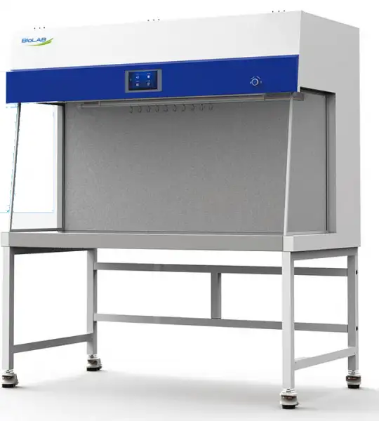
Horizontal Laminar Airflow BDL-2702
- 1. The cabinet is designed with a 10° inclination angle, the operation perspective is wide and more humanized.
- 2. Made of high quality cold rolled steel plate material, welding structure, surface electrostatic spraying, enhancing the stability of the cabinet.
- 3. Equipped with initial effect filter, which can preliminarily filter large particulate matter, thus improving the service life of the high efficiency filter.
- 4. Work surface is made of high quality 304 stainless steel material, beautiful and corrosion resistance.
- 5. The front window adopts 5mm thick tempered glass to better protect the safety of personnel and experiments.
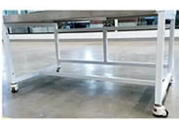
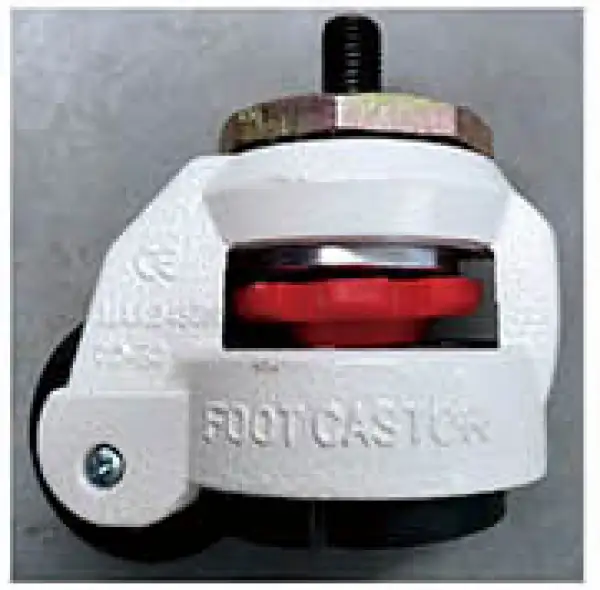
- 6. The base bracket and casters are integrated design, which can be moved safely through the casters and can also be fixed and leveled.
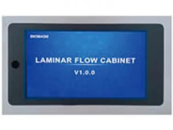
- 7. 7-inch color touch screen, real-time display of running status (air flow direction, air velocity, machine running time, UV lamp running time, high efficiency filter running time, high efficiency filter running resistance, operating area temperature and humidity, clock display) at a glance.
- 8. With the function of appointment timing, it can automatically set the time of starting and shutting down the laminar flow cabinet and the disinfection time of ultraviolet lamp.
- Up to 3-Year Product Warranty
- US & EU Compliance Standards
- Door-to-Door Shipping
Technical Specifications
Detailed operating and construction parameters for this model.
| Model | BDL-2702 |
| Internal Size (W*D*H) | 1700*500*730mm |
| External Size (W*D*H) | 1800*800*1930mm |
| Flow Mode | Horizontal Flow |
| Number of Users | 1~3 |
| Rated Power | 2000VA (including operating area socket load 500VA) |
| Power Supply | 220V±10%, 50Hz(Standard); 110±10%V, 60Hz(Optional) |
| Airflow Velocity | 0.2 m/s~0.45 m/s |
| Noise | ≤65dB(A) |
| Lighting | ≥300lx |
| Vibration | ≤5μm(rms) |
| Safety | Colonies Number≤0.5CFU/30min |
| Clean Grade | 1SO Level 5 (100 levels) |
| Filtration Efficiency | HEPA (H14) high efficiency filter, filtration efficiency for 0.3um particle=99.995% |
| Work Surface Height | 750mm(Customized) |
| Standard Accessory | LED lamp*2, UV lamp*2, Base stand, Waterproof socket*2, Temperature and humidity sensor |
| Optional Accessory | Armrest*2 |
| Net Weight | 260 kg |
| Gross Weight | 355 kg |
| Package Size(W*D*H) | 2060*1010*1500mm |
Product Features
Key design, performance, usability, and safety advantages.
1. The cabinet is designed with a 10° inclination angle, the operation perspective is wide and more humanized.
2. Made of high quality cold rolled steel plate material, welding structure, surface electrostatic spraying, enhancing the stability of the cabinet.
3. Equipped with initial effect filter, which can preliminarily filter large particulate matter, thus improving the service life of the high efficiency filter.
4. Work surface is made of high quality 304 stainless steel material, beautiful and corrosion resistance.
5. The front window adopts 5mm thick tempered glass to better protect the safety of personnel and experiments.
6. The base bracket and casters are integrated design, which can be moved safely through the casters and can also be fixed and leveled.
7. 7-inch color touch screen, real-time display of running status (air flow direction, air velocity, machine running time, UV lamp running time, high efficiency filter running time, high efficiency filter running resistance, operating area temperature and humidity, clock display) at a glance.
8. With the function of appointment timing, it can automatically set the time of starting and shutting down the laminar flow cabinet and the disinfection time of ultraviolet lamp.
9. With a key disinfection function, convenient and fast, greatly saving the work time and improving the work efficiency.
10. Perfect alarm system:
(1) Ultra-high filter pressure alarm: when the filter resistance increases, sound alarm will be issued.
(2) Filter failure replacement alarm: when the filter service life expires, there will be a filter replacement sound alarm.
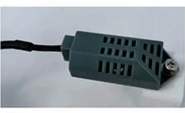
Temperature and, Humidity Sensor
LED Display, Digital LED Display: Airflow Level
Base Stand
Footmaster Caster, Universal Caster with, Brake and Leveling Feet
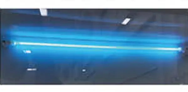
UV Lamp
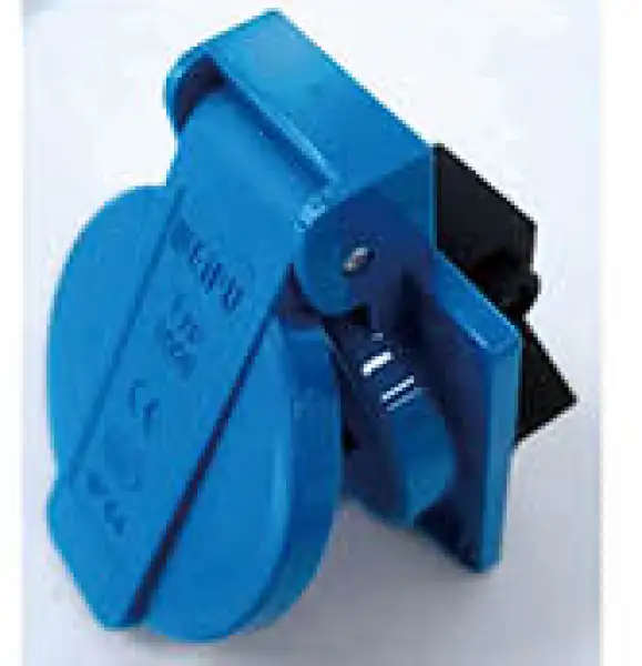
Waterproof Socket
Operating Manual View instructions, operating procedures, safety information, and maintenance guidance.
1. Product Introduction
1.1 Product Description
1.2 Product Features
1.3 Technical Parameters
1.4 Product Structure
2. Installation
2.1 Installation Environment
2.2 Location Selection
2.3 Installation Steps
2.4 Check after Installation
3. Operating Instruction
3.1 Main Screen Introduction
3.2 Settings Interface
3.3 Introduction to the Usage Process
4. Maintenance
4.1 Comprehensive Maintenance Cycle
4.2 Maintenance and Repair Methods
5. Handling of Common Problems
6. Simple Parts Replacement
6.1 Replace the Fuse
6.2 Replace the UV Lamp
6.3 Replace the LED Lamp
7. Precautions
7.1 Storage Conditions
7.2 Transportation Conditions
7.3 Cautions
8. Label Description
9. Warranty
Appendix Wiring Schematic Diagram
1. Product Introduction
1.1 Product Description
There are strict requirements for the cleanliness of the air in the work area including laboratories, electronic technology, aerospace, precision equipment and other fields at present. And clean air technology is also required in biological fields such as medicine and health, biopharmaceuticals, food, medical science experiments, sterile microorganisms, etc. Laminar Flow Cabinet is an ideal local air purification equipment to improve the clean working environment.
The cleanliness of the Laminar Flow Cabinet work area can reach ISO class 5, which can effectively improve the process conditions, ensure the accuracy of products and provide a sterile environment in the fields of scientific experiments and biological experiments.
1.2 Product Features
1.2.1 Classification
Horizontal laminar flow, single-sided operation.
1.2.2 Structure
1) The surface of the cabinet is electrostatic sprayed, and 1.2mm cold-rolled steel plate and welded structure are used to enhance the structural strength and stability of the cabinet.
2) The work surface is made of stainless steel, which is beautiful and corrosion-resistant.
3) The bracket is made of metal with electrostatic spraying on the surface.
4) The control panel adopts a touch switch to make the cabinet appearance beautiful and easy to operate.
1.2.3 UV sterilization
This Laminar Flow Cabinet using UV-C type 254nm wavelength UV sterilization, which can not only kill the active cells of microorganisms, but also kill strong heat-resistant budding spores and other mold spores, in addition that phage and viruses can quickly break under UV rays.
1.3 Technical Parameters
Type | BDL-2701 | BDL-2702 |
Dimension (W*D*H) | 1500*800*1730mm | 1800*800*1930mm |
Work area size (W*D*H) | 1400*500*600mm | 1700*500*730mm |
Air flow type | Horizontal flow | |
Work surface height | 750mm | 750mm |
HEPA filter | HEPA without partitions, with 99.995% filtration efficiency for φ0.3μm particles. | |
HEPA specification | 1420*630*69mm | 1620 *665*69mm |
Noise | ≤65dB(A) | |
Illumination | ≥300 lx | |
Vibration | ≤5μm(rms) | |
Temperature rise | ≤8°C | |
Display | LCD (Liquid Crystal Display) | |
Splash-proof socket | The power of the equipment used does not exceed 500W. | |
Grounding resistance | ≤0.1Ω | |
Power supply | AC220V,50 Hz(Standard) AC110V, 60Hz (Optional) | |
Work area | 304 brushed stainless steel | |
Cabinet | The cabinet is made of 1.2mm (1mm) thick cold-rolled steel plate and the surface is electrostatically sprayed. | |
UV Lamp appointed timing | UV lamp delayed 10s open to protect the safety of the operator. | |
UV Lamp | 30W | 40W |
LED lamp | 16W | 16W |
Airflow velocity | 0.2-0.45m/s | 0.2-0.45m/s |
Safety | Colony forming unit ≤0.5CFU/30min | |
Startup password | Default 1000 | |
1.4 Product Structure
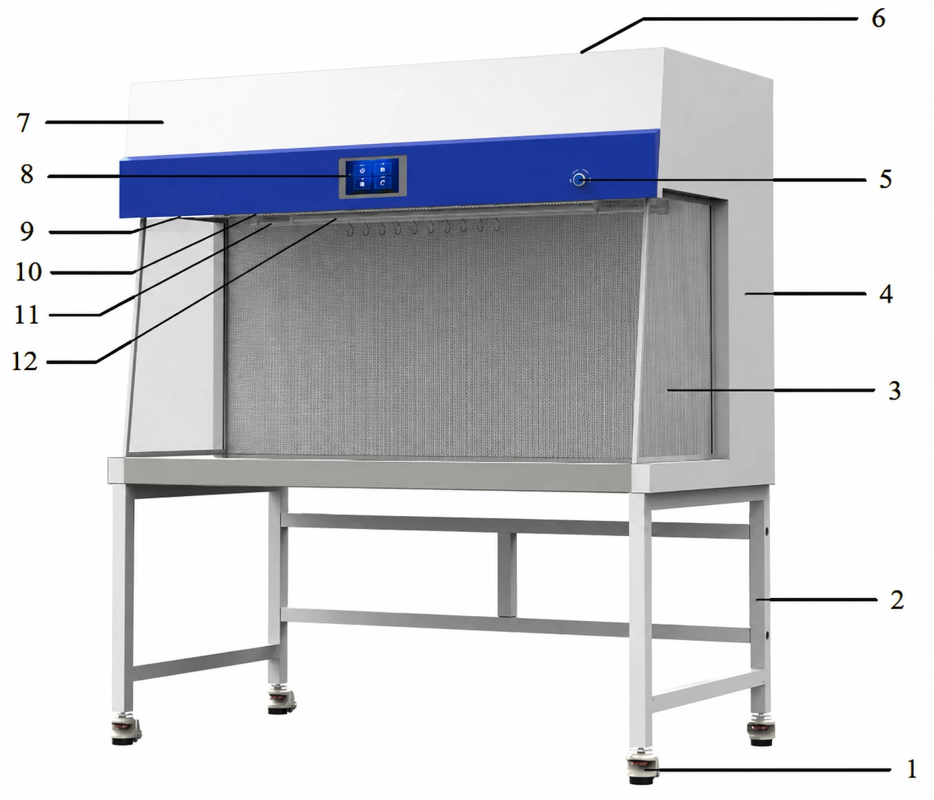
Figure 1
1 | Footmaster caster | 2 | Base stand | 3 | Side window |
4 | Upper cabinet | 5 | Button switch | 6 | Power socket |
7 | Control panel | 8 | LED screen | 9 | Waterproof socket |
10 | LED lamp | 11 | UV lamp | 12 | Hook hanger |
Table 1
 Caution
The power of the cabinet used on the receptacle should not exceed 500W (rated voltage * rated current 220V * 2.3A).
The waterproof receptacle as waterproof only when its front cover is lay down; the receptacle cannot be considered as waterproof when the front cover is opened.
Note: IP44 is the socket degree of protection. According to IEC 60529: Protected the inside of the socket against foreign solid objects of 1.0mmΦ and greater from contacting the internal parts; protected the socket against splashing water from all directions from causing damage.
2. Installation
Caution
This Laminar Flow Cabinet needs to be installed by our trained and qualified engineers.
1. Remove all packaging components.
2. Inspect the external surface of the host for scratches, deformations or foreign objects.
3. Carefully inventory accessories and information according to the packing list in the manual.
4. Move the entire cabinet to a position as close as possible to the final location and easy to install.
Caution
When handling the Laminar Flow Cabinet, it is strictly forbidden to place or disassemble it upside down.
2.1 Installation Environment
a. Indoor use.
b. Humidity: ≤80%.
c. Power supply voltage: AC 220V(Standard) AC 110V(Optional).
d. Transient overvoltage: Facility category (overvoltage category) Ⅱ.
e. Rated pollution level: Class 2.
2.2 Location Selection
Laminar Flow Cabinet should be installed in the clean laboratory or indoor environment away from the dust source and vibration source, not at the channel. If the laboratory has windows, it should always be in the closed state. Laminar Flow Cabinet should not be placed in the circulation air entrance, so that the air can blow over the former operation area or blow to the HEPA.
If space allows, there should be 30cm space behind and around the Laminar Flow Cabinet for cleaning, if not, there should be minimum 8cm per side and 3.8cm space at the back.
The Laminar Flow Cabinet power outlet can be closed to facilitate the maintenance, and there is no need to move the device to ensure electrical safety.
The power outlet can be closed to facilitate the maintenance, and the safety of electrical appliances can be ensured without moving. Do not place the device in a position where it is difficult to disconnect the power supply.
2.3 Installation Steps
a. After moving to the designated indoor location, remove the packing material, check the device and accessories according to the packing list to make sure there is no damage during transportation.
b. Assemble and place the base stand
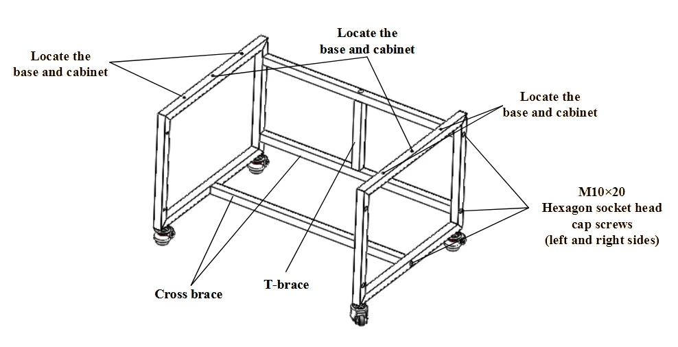
Figure 2
Screw out the M10x55 hexagon socket head cap screws in the cross brace and T brace, assemble the base tightly and firmly refer to the above figure.
c. Connect the upper cabinet and stand base
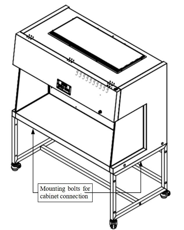
Figure 3
According to the above diagram, use M10x55 hexagon socket head cap screws, flat washers Φ10, spring washers Φ10 to fasten firmly through the base and side plate from the bottom up.
d. Place the whole device
The Laminar Flow Cabinet should be placed in a protected area of airflow to prevent the airflow from the ventilation system, air conditioner, door, window and personnel movement.
Caution
The cabinet should be installed in a wide and more spacious space .
When moving the cabinet, you need to cut off the power and adjust the casters first and then move slowly.
e. Caster adjustment
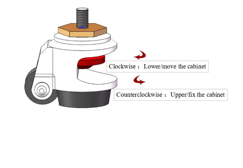
Figure 4
Rotate the red part of the caster clockwise, lower the corresponding base legs, lower the height of the cabinet, then lower four casters at the same time to move the cabinet position; counterclockwise rotate the red part of the caster, raise the corresponding base legs, raise the height of the cabinet, raise four casters at the same time to fix the cabinet; four casters can be adjusted at the same time to make the cabinet in the horizontal stable state.
2.4 Check after Installation
After powering up, check the following items according to the normal use process.
Test item | Normal condition |
Normal power on-off | Connect the power supply and power on. |
Fan operation | Click the "Fan" button,fan works normally. |
LED lamp | Click "LED lamp" button, the LED lamp is on. |
Waterproof socket | Click "Waterproof socket",output power is AC 220V(Standard) AC 110V(Optional ) tested by multimeter. |
Table 2
This product is placed in laboratory sections or teaching laboratories.
The installation location should be far away from dust and vibration sources.
Be sure to plug the power supply into an outlet with a ground wire and ensure that the ground terminal is reliably grounded, and use a power supply with a leakage protection device.
The interior and surroundings of the cabinet must be carefully cleaned after installation using a vacuum cleaner or a tool that does not produce fibers.
Test the average velocity of working area with an anemometer after installation and cleaning. When the average airflow velocity is less than 0.2m/s, the airflow velocity should be increased. On the contrary, when the average airflow velocity is greater than 0.5m/s, it should be reduced.
Caution
If there is any problem please contact your local dealer for installation adjustment.
3. Operating Instruction
3.1 Main Screen Introduction
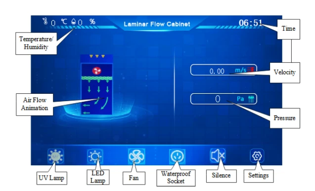
Figure 5 (Home Screen)
Temperature/Humidity: Real-time measurement and display of temperature and humidity in the operation area.
Air Flow Animation: When the device is running, display the air flow direction, when close the fan, the animation stops.
UV Lamp: Control the switch of UV lamp.
Note: UV lamp and LED lamp have a chain mechanism, only when the fan and LED lamp are closed can UV lamp be opened.
LED Lamp: Control the open and close of LED lamp.
Fan: Control the fan switch.
Waterproof socket: Control the power on and off of waterproof socket.
Silence: Switch sound on and off. "x" is in front of the horn when the sound is off.
Settings: After clicking "Settings", it enters the settings interface, which allows you to set the following contents: "Timing Switch", "Fan Settings", "Equipment Life", "Standby Settings".
Pressure: Real-time display of the pressure difference value before and after the filter.
Velocity: Real-time display of horizontal airflow velocity magnitude.
Time: Real-time display of the current date and time.
3.2 Settings Interface
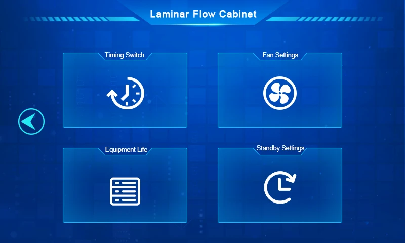
Figure 6 (Home Screen)
Click "Settings" to enter the settings interface, where you can configure the items shown in the image. Click "Fan Settings," enter the password 666666, and access the fan settings interface. Click "Fan Settings", enter the startup password (default 1000) to access the interface, and change the startup password. The entered value will become the new startup password.
3.2.1 Timing switch
Click "Timing Switch" in the above figure to enter the timing switch interface, click "Time Input/Display Area" to input the value to be timed, and then you can switch the timing for the corresponding time.
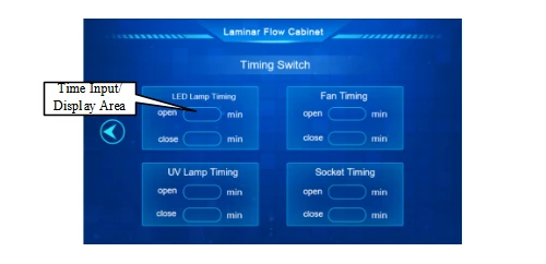
Figure 7 (Timing switch function setting)
Caution
In order to protect users, the UV lamp is turned on with a delay of 10 seconds by default. If users have other delay needs, you can set the UV lamp to turn on at a time on this interface. Before turning on the UV lamp, the user should set the timer off on this interface. In order to achieve a good effect of air and surface disinfection, the irradiation time of the UV lamp should be ≥30min.
3.2.2 Equipment life
Click "Equipment Life" to enter the equipment life display interface, which can display the UV lamp used time, the equipment used time and filter used time. If the UV lamp or filter is replaced, it is needed to reset the time. Click "Time Display Area", enter the password that can be obtained from the manufacturer.
Caution
If the filter needs to be replaced, please contact our customer service center or local agent.
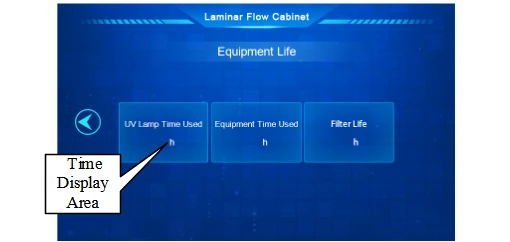
Figure 8 (Equipment life)
3.2.3 Standby settings
The standby time is the time when the screen is darkened and enters the screen protection state.
Click "Standby Settings" to enter the standby settings interface, click the number in the "Standby Time Display Area" to modify the standby time.
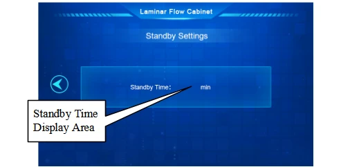
Figure 9 (Standby time setting)
3.3 Introduction to the Usage Process
(1) Before the experiment:Click the UV lamp, turn on the UV lamp, disinfect for more than half an hour.
(2) Open the fan, after running for half an hour can the experiment be started.
(3) After the experiment, click the UV lamp, turn on the UV lamp and disinfect for more than half an hour.
(4) After use, unplug the power supply and place it in suspension to avoid power contact with moisture and water to avoid leakage.
Caution
(1) When using a UV lamp for disinfection, people should leave the room to protect their eyes and skin from inadvertent exposure.
(2) The intensity of the UV lamp should be tested regularly according to the manufacturer's specifications, and it is recommended that it be replaced once a quarter if it fails to pass.
4. Maintenance
The operability and safety of this device can only be guaranteed if there are enough competent personnel and units for inspection, maintenance and repair.
4.1 Comprehensive Maintenance Cycle
Maintenance should be performed weekly, monthly, annual, or every 1000 work hours, as well as every restart.
4.2 Maintenance and Repair Methods
4.2.1 Cleaning
Under normal circumstances, cleaning only requires a small amount of household or commercial dishwashing detergent, which can be dissolved in water and wiped the dirt on the surface directly.
(1) When used for the first time or use again after long time out of use
You should first use a dry cleaning towel to remove the surface of the floating dust, after wiping with a clean towel several times, make sure that there is no dust, spray medical alcohol on the medical gauze to disinfect the work area, laminar flow plate and work surface, comprehensively. Before use, turn on the UV sterilization lamp to disinfect, 30 minutes later turn off the UV sterilization lamp and press the fan key, the fan will run.
(2) When used continuously
After using the device every day, first clear all the debris on the work surface, wipe it again with a dry and wet cleaning towel, and finally disinfect the work area, laminar flow plate and work surface with medical alcohol spray on medical gauze comprehensively and prepare for use on the next day.
Caution
You can only spray alcohol on the medical gauze with alcohol spray, do not spray alcohol on the laminar flow plate, because the laminar flow plate has a HEPA, which can not be subject to moisture.
4.2.2 Regular maintenance
a. Daily or weekly maintenance
Use medical alcohol to disinfect and clean the device.
Disinfect and clean the control panel with medical alcohol.
Use flexible cleaning agent or glass-specific cleaning agent to clean the outer surface of the device and glass.
Check each function of the device according to the user manual.
b. Monthly maintenance
Surface cleaning.
Check functions of the device, disinfection of the interior of it.
Record this maintenance.
c. Annual maintenance
Check UV lamp and LED lamp.
Conduct a thorough inspection of the device's performance for the safety of it. The maintenance fee is paid by the user.
Record this maintenance.
Caution
a. Before daily maintenance, cut off the power supply.
b. Since the statistics of operation time will directly affect the judgment of maintenance needs, we suggest that a detailed record of operation time should be prepared when using the device for reference and inquiry.
c. The fan must be inspected and maintained regularly.
d. Surface cleaning: To keep the cabinet clean, please clean it regularly (at least once a week is recommended). When wiping, dip a soft cloth in soapy water and then wring it out. Do not spray any chemical reagent on the operation panel or other labels to prevent discoloration or illegible label film. Clean the outer surface of the cabinet and glass with a flexible cleaning agent or glass-specific cleaning agent for glass.
5. Handling of Common Problems
When there are doubts, suspicion of device failure in the process of use, you can first refer to the following content to troubleshoot.
Before diagnosing a fault, check whether the power supply is properly connected, the power cable is obviously damaged, the fuse is in good condition, and the button switch is on.
Fault | Position | Judgement | Solution |
LED lamp light is not bright or abnormal | Lamp tube | Check whether the lamp is damaged. | If damaged, replace it. |
Circuit | Check whether the cable is in poor contact. | If yes, reconnect the cables. | |
Control board | Rule out other damage. | Replace control board. | |
UV lamp does not light up or abnormal | Lamp holder | Check whether the lamp tube is firmly connected to the lamp holder, or the lamp holder is damaged. | If not, tighten it. If damaged, replace lamp holder. |
Lamp tube | Check whether the lamp is damaged. | If damaged, replace it. | |
Ballast | Check whether the ballast is damaged. | If damaged, replace it. | |
Circuit | Check whether the cable is in poor contact. | If yes, reconnect the cables. | |
Control board | Rule out other damage. | Replace control board. | |
Fan failure | Fan | Check whether the fan is damaged. | If damaged, replace it. |
Circuit | Check whether the cable is in poor contact. | If yes, reconnect the cables. | |
Touch screen control is not sensitive | Circuit | Check whether the cable is in poor contact. | If yes, reconnect the cables. |
Touch screen | Rule out other damage. | Replace control board. | |
No power to waterproof socket | Fuse | Check whether the fuse is in good condition. | If damaged, replace it. |
Waterproof socket | Inspect waterproof socket for damage. | If damaged, replace it. | |
Circuit | Check whether the cable is in poor contact. | If yes, reconnect the cable. | |
Circuit board | Rule out other damage. | Replace circuit board. | |
Device power-off | Power supply | Power supply is not connected well. | Reconnect. |
Power cord | Check whether the power cord has obvious damage. | If damaged, replace it. | |
Fuse | Check whether fuse is good. | If not, replace it. | |
Transformer | Check whether transformer output is normal. | If not, replace it. | |
Control board | Rule out other damage. | Replace circuit board. |
Table 3
 Caution
The operation of the above electrical components must be carried out by a qualified electrician under safe conditions (cut off the power). And other parts are not allowed to disassemble, otherwise the consequences are borne by the user.
If there is other failure that is not in above list, or the operator can not immediately solve, please immediately notify our company's service department immediately, for your safety, please do not repair the device by yourself;
The maintenance work of this device can only be undertaken by trained and approved technical personnel;
If you need to order parts, please find our technical service department, please indicate the model and number of the device you purchased.
6. Simple Parts Replacement
Operation of all electrical components of the device must be carried out by a qualified electrician under safe conditions. When the device has malfunction and the operator can not immediately troubleshoot, please notify the maintenance personnel immediately. Please do not repair the device by yourself for your safety.
If you need to order parts, you can find our technical service department, inform us of the model and number of the device you have purchased.
6.1 Replace the Fuse
Socket fuse [Φ5*20(5A)] is located on the right outside of the cabinet. When you replace it, first turn off the power and unplug it, use a cross screwdriver to press and screw the fuse holder counterclockwise, take off the fuse in the fuse holder and replace it with a new fuse of same specification, then press and screw the fuse holder clockwise to replace it; fire line fuse [Φ5*20(10A)] is also located on the right side, use a flat-head screwdriver to remove the fuse holder and replace the fuse with a new one, then press it back.
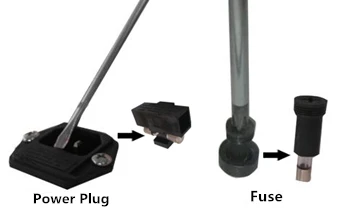
Figure 10
6.2 Replace the UV Lamp
The product is equipped with a life of UV lamp (T8, 40W) for a cumulative working time of 600 hours. We recommend that you regularly test the UV intensity in order to achieve a good disinfection effect. You can use the UV intensity test card to confirm whether you need to replace the UV lamp or not. When replacing, first disconnect the power supply, then remove the lamp by screwing it 90°, take out a new UV lamp of the same specification, put it on the lamp holder and screw 90° in the opposite direction.
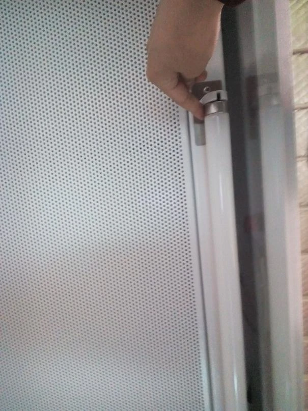
Figure 11
Put your hands on both ends of the lamp that near both sides of the lamp holder, and at the same time rotate the lamp clockwise (or counterclockwise) for 90°, then the lamp can be removed as shown, carefully placed aside, take out a new UV lamp and insert it into the lamp holder, rotate 90°clockwise (or counterclockwise). When installation is complete, turn power on to test.
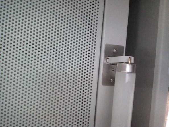
Figure 12
6.3 Replace the LED Lamp
When the LED lamp needs to be replaced, please disconnect the power supply. Then tilt the LED integrated bracket to remove, unplug the right bracket connector, replace the new LED light and install back the bracket connector, and tilt the LED integrated bracket into the LED bracket slot.
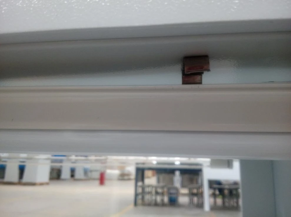
Figure 13 (LED Bracket Slot)
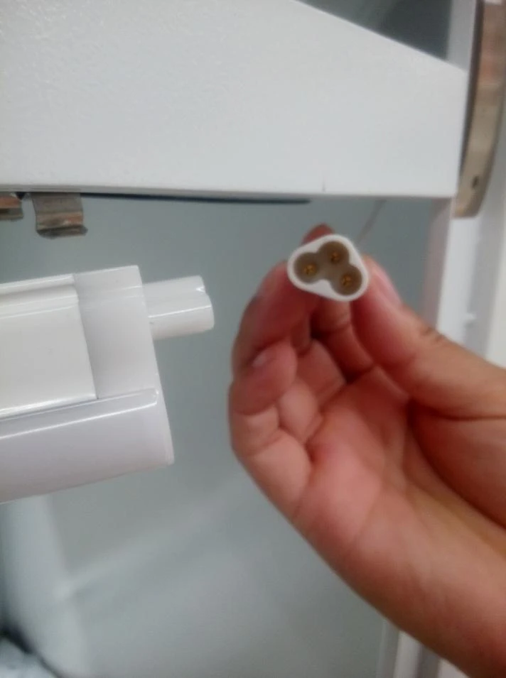
Figure 14 (LED Bracket Connector)
Caution
(1) It is forbidden to wipe the lamp with a wet cloth while cleaning in the powered state.
(2) It is forbidden to do the replacement in the powered state.
7. Precautions
7.1 Storage Conditions
The device should be stored in the warehouse with relative humidity not more than 75%, temperature less than 40°C, good ventilation, no acid, alkali and other corrosive gases. The storage cycle should not exceed one year. If it is stored for more than one year, the open-package inspection is needed and only after passing the inspection can it be used again.
7.2 Transportation Conditions
The device should be transported in full accordance with the requirements shown on the outer surface of the packing area. The user should check the integrity of the packing area carefully when receiving the device with the packing area sent by the logistics company. If the packing area has damage, extrusion and other phenomena, please refuse to sign, and contact our company in time.
Caution
Please contact with us in time when the Laminar Flow Cabinet that has been installed and used is relocated and moved again.
7.3 Cautions
(1) Before connecting the AC power supply, please ensure that the voltage of the power supply is consistent with input voltage and stable, ensure that the rated load of the power socket is not less than the requirements. The cabinet adopts a grounding plug, which has the third leg that could only match with a grounding type power socket, so it is a safety device. If the plug can not be inserted into the socket, you should ask an electrician to install a grounding type power socket. Be sure to confirm good grounding when using.
(2) During the using process of the device, do not put soft, fine items (For example: soft tissue paper) on the work surface, avoid sucking them into the negative pressure duct and fan by the inlet, which can affect the operation of the device.
(3) The maximum weight of items placed in the cabinet should not exceed 23kg/25x25cm2.
(4) Avoid vibration: Avoid the use of vibrating equipments (such as centrifuges, vortex oscillators, etc.) in the cabinet, because the vibration will cause the accumulation of particulate matter on the filter membrane to shake off, resulting in a reduction in the internal cleanliness of the work area. At the same time, if the balance fails on the front work surface, it will also cause pollution the operator.
(5) Open flame is prohibited: The use of open flame is prohibited in the cabinet. Open flame's usage will lead to flocculation of airflow in the work area, and will damage the filter. During the process of experiments that require high temperature sterilization, it is highly recommended to use infrared sterilizer.
(6) Service life of HEPA. With the extension of the use period, dust and bacteria accumulation in the filter will lead to the increase of HEPA pressure loss. When the increase of the velocity can not meet the requirements, you must promptly contact our service department to replace the HEPA, otherwise it will affect the safety of the device.
Replaced filter should be disposed according to the medical waste.
(7) The fan and its lower side steel plate is the plenum cover, these air ducts are strictly sealed when leave factory and needed to maintain their tightness. The operator should not loosen or remove the screws of these parts. If there is a special need, it must be handled by our service personnel.
Caution
Solemnly declare: If the device is not used in accordance with the methods prescribed by the company, it may damage the protection provided by the device, and the company should not be responsible for the risks caused by the operation that is not in accordance with the provisions!
8. Label Description
| 10A Fuse Label |
| 5A Tubular Fuse for Socket Label |
| 10A Tubular Fuse for Blower Label |
| Grounding Label |
| UV Lamp Warning Label |
| Load Requirement Label |
| Filter Upstream Label |
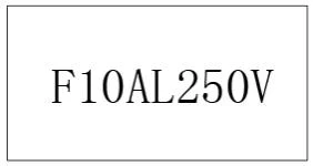
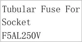
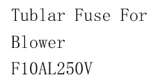


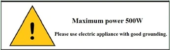

Table 4
9. Warranty
The warranty period of the purchased product and maintenance contents are subject to the sales contract.
In the warranty period of the device, if the user improperly use caused by failure or damage, the company does not assume warranty obligations.
Out of the warranty period, our company is also responsible for maintenance, but charged the corresponding maintenance fees.
The service life is 8 years, production date please see product label.
Appendix Wiring Schematic Diagram
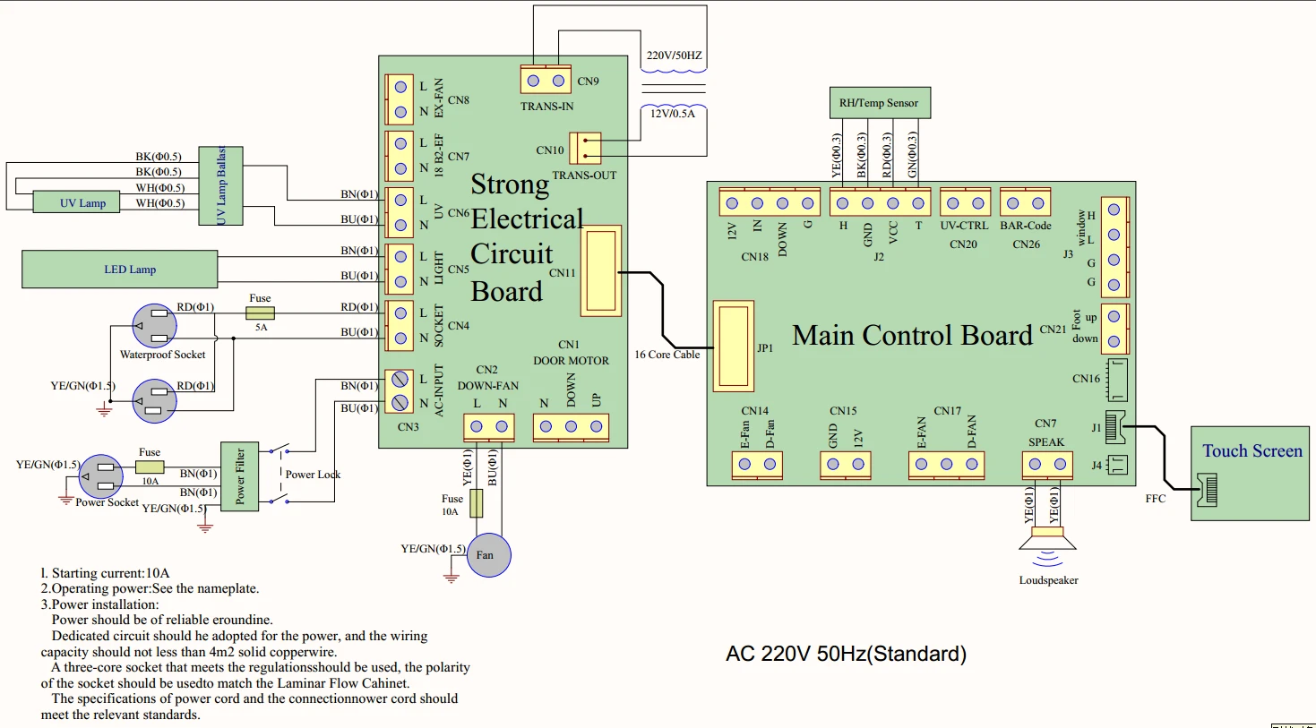
Figure 15
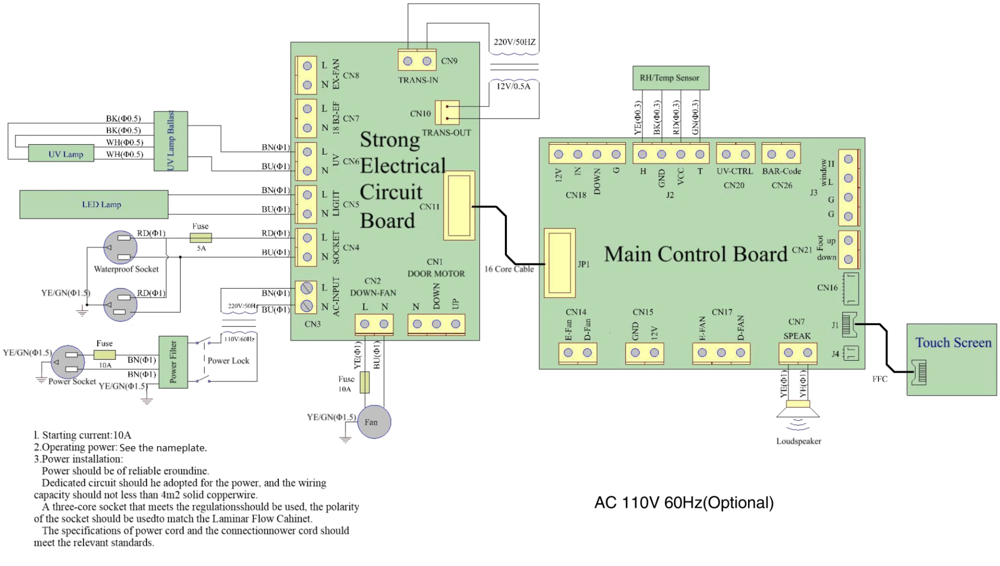
Figure 16