
Get Price
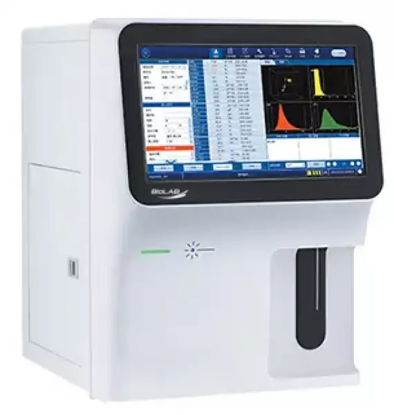
Hematology Analyzer BDL-6701
- Throughput: 60T/H.
- 14-inch touch screen.
- Tri-angle laser scatter + flow cytometry method + impedance method for counting.
- 3D holographic scattergram displays the accurate 5-part differentiation of WBC.
- Large storage capacity: 100,000 results (including histogram, scattergram, patient information).
- Up to 3-Year Product Warranty
- US & EU Compliance Standards
- Door-to-Door Shipping
Technical Specifications
Detailed operating and construction parameters for this model.
| Model | BDL-6701 |
| Throughput | 60 Tests/hour |
| Assay Items | 5 parts, 29 parameters, 3 histograms, 3D scattergram |
| Principle | Tri-angle laser scatter, Flow cytometry method, 3D scattergram analysis, Impedance method for RBC and PLT counting, Cyanide free reagent for HGB test |
| Test Mode | CBC mode, CBC+DIFF mode Venous whole blood, Capillary whole blood and Prediluted |
| Parameters | WBC, RBC, HGB, HCT, MCV, MCH, MCHC, RDW-SD, RDW-CV, PLT, MPV, PCT, PDW, P-LCR, P-LCC, NEU%, LYM%, MON%, EO%, BAS%, NEU#, LYM#, MON#, EOS#, BAS# |
| Research Parameters | 4 research parameters: ALY%, ALY#, IG%, IG# |
| Performance | |
| --Linearity range | |
| WBC | 0~300*10^9/L |
| RBC | 0~300*10^12/L |
| HGB | 0~250g/L |
| PLT | 0~3000*10^9/L |
| --Carry Over | |
| WBC | ≤0.5% |
| RBC | ≤0.5% |
| HGB | ≤1.0% |
| PLT | ≤1.0% |
| --CV | |
| WBC | ≤2.0% |
| RBC | ≤1.5% |
| HGB | ≤1.5% |
| PLT | ≤4.0% |
| Sample Volume | CBC+DIFF mode: ≤20μl ; CBC mode: ≤10μl |
| Storage | 100,000 results including histogram, scattergram and patient information |
| Interface | 4 USB ports, 1 LAN port bi-direction LIS, support HL7 protocol, Internal RFID reader |
| Power Supply | AC220V±10% 50/60Hz; 110V±10% 60Hz; 400VA |
| Package Size (W*D*H) | 575x490x690mm |
| Gross Weight | 43kg |
| Reagent Package Size | 330*330*330mm, 400*290*240mm, 400*290*240mm |
| Reagent Gross Weight | 22kg, 2kg, 2kg |
Product Features
Key design, performance, usability, and safety advantages.
Operating Manual View instructions, operating procedures, safety information, and maintenance guidance.
1. Using This Manual
1.1 Introduction
1.2 Who Should Read This Manual
1.3 Conventions Used in This Manual
1.4 Safety Information
1.5 Symbols
2. Understanding your analyser
2.1 Introduction
2.2 Intended Use
2.3 Main Structure
2.4 User Interface
3. Understanding the system principles
3.1 Introduction
3.2 Aspiration
3.3 Dilution
3.4 WBC Measurement
3.5 RBC/PLT Measurement
3.6 HGB Measurement
4. Installing your analyser
4.1 Introduction
4.2 Installation Requirements
5. Start-up
5.1 Introduction
5.2 Precautions before Power-on
5.3 Logging on System
5.4 System Setup
1. Using This Manual
1.1 Introduction
This chapter explains how to use your BDL-6701 operator's manual, which is shipped with your BDL-6701 Auto 5-part Hematology Analyzer and contains reference information about the BDL-6701 and procedures for operating, troubleshooting and maintaining the analyzer. Read this manual carefully before operating your analyzer and operate your analyzer strictly as instructed in this manual.
1.2 Who Should Read This Manual
This manual contains information written for clinical laboratory professionals to :
Learn about the BDL-6701 hardware and software.
Customize system settings.
Perform daily operating tasks.
Perform system maintenance and troubleshooting.
1.3 Conventions Used in This Manual
This manual uses certain typographical conventions to clarify meaning in the text:
All capital letters enclosed in [ ] indicate a key name on the external keyboard, such as [ENTER].
Bold letters included in " " indicate text you can find on the screen, such as "Clean".
Bold letters indicate chapter titles, such as Chapter 1 Using This Manual.
All illustrations in this manual are provided as examples only. They may not necessarily reflect your analyzer setup or data displayed.
1.4 Safety Information
The following symbols are used to indicate danger and alert information in this manual.
When you see… | Then… |
| Read the statement below the symbol. The statement is alerting you to a potentially biohazardous condition. |
| Read the statement below the symbol. The statement is alerting you to an operating hazard that can cause personnel injury. |
| Read the statement below the symbol. The statement is alerting you to a possibility of analyzer damage or unreliable analysis results. |
| Read the statement below the symbol. The statement is alerting you to information that requires your attention. |




Table 1
All the samples, controls, calibrators, reagents, waste and areas contacted with them are potentially biohazardous. Wear proper personal protective equipment (e.g. gloves, lab coat, etc.) and follow safe laboratory procedures when handling them in the laboratory.
If leaking happens to the analyzer, the leak is potentially biohazardous.
Please check the firmness of all the doors, covers and boards before running the analyzer.
Make sure all the safety measurements are adopted. Do not disable any safety device or sensor.
Please take action to any alarm and error message immediately.
Do not touch the moving parts.
Contact Manufacturer or Manufacturer-authorized distributors immediately if any damaged part is found.
Be careful when opening/closing and removing/installing the doors, covers and boards of the analyzer.
Discard the analyzer according to government regulations.
Please operate your analyzer strictly as instructed in this manual.
Please adopt proper measurements to prevent the reagents from being polluted.
1.5 Symbols
You will find the following symbols in this manual :
When you see… | Then… |
| Read the statement below the symbol. The statement is alerting you to a potentially biohazardous condition. |
| Read the statement below the symbol. The statement is alerting you to an operating hazard that can cause personnel injury. |
| Read the statement below the symbol. The statement is alerting you to a possibility of analyzer damage or unreliable analysis results. |
| Read the statement below the symbol. The statement is alerting you to information that requires your attention. |


Table 2
You may find the following symbols of the analyzer system :
When you see… | It means… |
| CAUTION, CONSULT ACCOMPANYING DOCUMENTS. |
| The sample probe is sharp and potentially biohazardous, please be careful when operating. |
| BIOLOGICAL RISK |
| HIGH VOLTAGE |
| WARNING, LASER BEAM |
| CC |
| FOR IN VITRO DIAGNOSTIC USE |
| BATCH CODE |
| SERIAL NUMBER |
| CATALOG NUMBER (FOR CONTROLS) |
| DATE OF MANUFACTURE |
| MANUFACTURER |
| CONSULT INSTRUCTIONS FOR USE |
| THE FOLLOWING DEFINITION OF THE WEEE LABEL APPLIES TO EU MEMBER STATES ONLY: THE USE OF THIS SYMBOL INDICATES THAT THIS PRODUCT SHOULD NOT BE TREATED AS HOUSEHOLD WASTE. BY ENSURING THAT THIS PRODUCT IS DISPOSED OF CORRECTLY, YOU WILL HELP PREVENT BRINGING POTENTIAL NEGATIVE CONSEQUENCES TO THE ENVIRONMENT AND HUMAN HEALTH. FOR MORE DETAILED INFORMATION WITH REGARD TO RETURNING AND RECYCLING THIS PRODUCT, PLEASE CONSULT THE DISTRIBUTOR FROM WHOM YOU PURCHASED THE PRODUCT. |
| AUTHORISED REPRESENTATIVE IN THE EUROPEAN COMMUNITY |
| Indicates this device is in compliance with Europe Directive |















Table 3
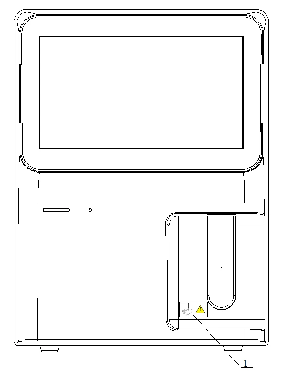
Figure 1 (Front of the analyzer)
The sample probe is sharp and potentially biohazardous, please be careful when operating.
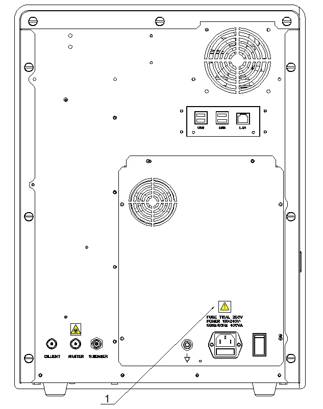
Figure 2 (Back of the Analyzer)
 Connect only to a properly earth grounded outlet.
To avoid electric shock, disconnect the power cord prior to removing or replacing fuse.
Replace fuse only with the type and rating specified.
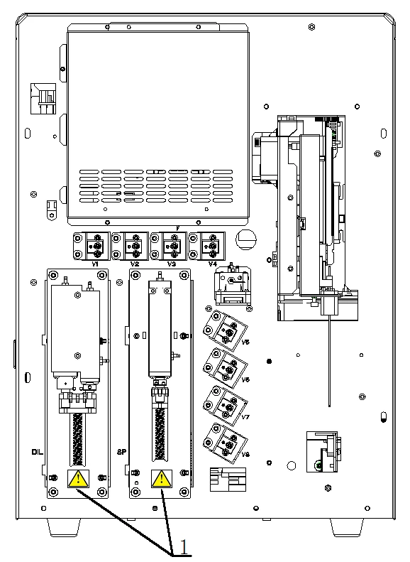
Figure 3 (Front of the analyzer (Front Cover Open))
To avoid injury, do not put your hands around the guide channel of the syringe
board.
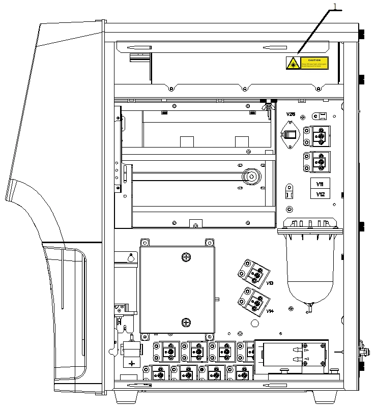
Figure 4 (Right Side of the Analyzer)
 Laser radiation when opening, avoid direct eye exposure.
2. Understanding your analyser
2.1 Introduction
The BDL-6701 Auto 5-part Hematology Analyzer is a quantitative, automated Auto 5-part Hematology analyzer and 5-part differential counter for in Vitro Diagnostic Use in clinical laboratories.
2.2 Intended Use
The purpose of this analyzer is to identify the normal patient, with all normal system-generated parameters, and to flag or identify patient results that require additional studies.
The BDL-6701 is a quantitative, automated hematology analyzer and 5-part differential counter used in clinical laboratories. It provides the following 25 basic parameters, 4 parameters for research use, 3 histograms and 1 scattergram of blood samples. It supports 2 measurement modes: CBC and CBC+DIFF.
Parameter Name | Abbr. | CBC | CBC+DIFF |
White Blood Cell count | WBC | * | * |
Neutrophils percentage | Neu% | / | * |
Lymphocytes percentage | Lym% | / | * |
Monocytes percentage | Mon% | / | * |
Eosinophils percentage | Eos% | / | * |
Basophils percentage | Bas% | / | * |
Neutrophils number | Neu# | / | * |
Lymphocytes number | Lym# | / | * |
Monocytes number | Mon# | / | * |
Eosinophils number | Eos# | / | * |
Basophils number | Bas# | / | * |
Abnormal Lymphocytes percentage | ALY% (RUO) | / | * |
Large Immature Cells percentage | LIC% (RUO) | / | * |
Abnormal Lymphocytes number | ALY# (RUO) | / | * |
Large Immature Cells number | LIC# (RUO) | / | * |
RBC | RBC | * | * |
Hemoglobin Concentration | HGB | * | * |
Mean Corpuscular Volume | MCV | * | * |
Mean Corpuscular Hemoglobin | MCH | * | * |
Mean Corpuscular Hemoglobin | MCHC | * | * |
Concentration | |||
Red Blood Cell Distribution Width Coefficient of Variation | RDW-CV | * | * |
Red Blood Cell Distribution Width Standard Deviation | RDW-SD | * | * |
Hematocrit | HCT | * | * |
Platelet count | PLT | * | * |
Mean Platelet Volume | MPV | * | * |
Platelet Distribution Width | PDW | * | * |
Plateletcrit | PCT | * | * |
Large Platelet count | P-LCC | * | * |
Large Platelet percentage | P-LCR | * | |
White Blood Cell Histogram | WBC Histogram | * | / |
Red Blood Cell Histogram | RBC Histogram | * | * |
Platelet Histogram | PLT Histogram | * | * |
Differential Scattergram | Diff Scattergram | / | * |
Table 4
"*" means the parameter is provided in the mode. "/" means the parameter is not provided.
ALY%, LIC%, ALY# and LIC# are parameters for research use only, not for diagnostic use.
2.3 Main Structure
The BDL-6701 Auto 5-part Hematology Analyzer consists of the main u n i t (analyzer) and accessories.
Please check the firmness of all the doors, covers and boards before running the analyzer.
The analyzer is heavy, to move it by one person may cause injury. It is advisable for two people to move it together when transport is needed, and make sure you follow the instructions and use the proper tools.
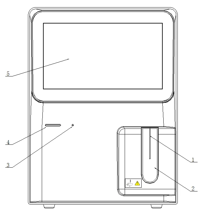
Figure 5 (Front of the Analyzer)
1. Sample probe 2. Aspirate key
3. Laser indicator 4. Power/Status indicator 5. Screen
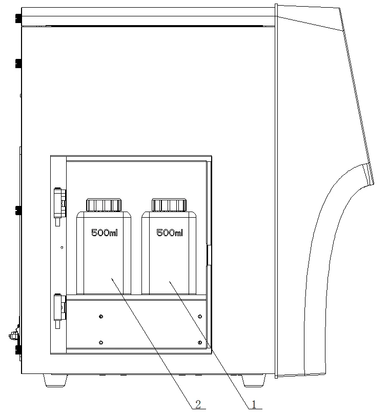
Figure 6 (Left side of the Analyzer)
1. W-61LH Lyse inlet
2. W-61LD Lyse inlet
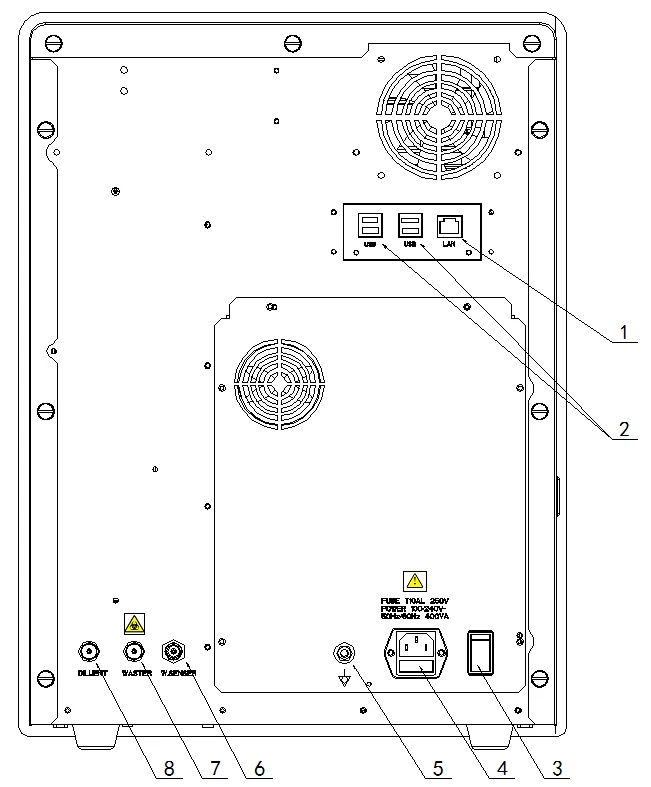
Figure 7 (Back of the Analyzer)
1. Network interface 2. USB interface
3. Power Switch 4. AC input
5. CC 6. Waste sensor
7. Waste outlet 8. W-61D diluent inlet
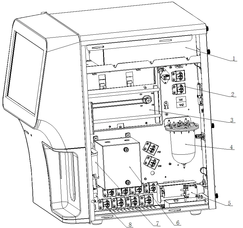
Figure 8 (Right Side of the Analyzer (Right Door Open))
1. Optical system 2. Fluidic valves
3. Sampling module 4. Vacuum chamber
5. Pumps 6. Bath
7. DIFF bath 8. Buffer chamber
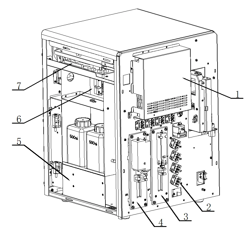
Figure 9 (Left Side of the Analyzer (Left Door Open and Front Cover Removed)
1. IPC cover
2. Fluidic valves
3. Syringes
4. Syringes
5. Reagent chamber
6. Liquid level detection unit
7. PCBA
Main Unit (Analyzer)
The main unit (analyzer) is the principal part of the product. It performs the sample analysis and the data process.
Power/Status Indicator
The Power/Status indicator is located in the middle of the left side of the analyzer (front side). It tells you about the status of the analyzer including ready(green), running(yellow) and error(red).
Power Switch
A power switch is on the back of the analyzer. It starts up or closes down the analyzer.
 To avoid damage, do not turn on/off the power of the analyzer continually in a short time.
Aspirate Key
The aspirate key is located behind the sample probe. You can press the key to start the selected analysis cycle, dispense diluent and wake up the analyzer from sleep.
Network Interface
A network interface is located on the back of the analyzer. It connects to the external computer.
2.4 User Interface
After the starting procedure, you will enter the user interface.
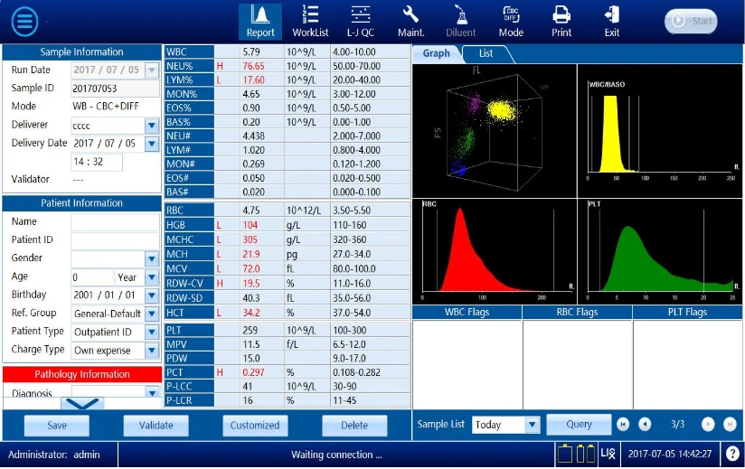
Figure 10
The interface can be divided into several areas as follows according to their
functions:
1. Information area of the user logged on
This area displays the name and access level of the current user.
2. Information area
It displays the information about the sample ID, analysis mode (whole blood/predilute blood) and measurement mode (CBC/CBC+DIFF) of the next sample. Or other information about the status of the analyzer such as error messages.
3. Reagent Status area
There are status for the remaining of three reagents.
4. LIS/HIS status
Gray icon: disconnected Colorful icon: connected
5. System time
It displays the time of the operation system.
6. Help
You can click the  button to display help information.
7. Menu button
You can click the  button on the left top corner to open the system menu. Click a menu option, a relevant screen or message box will appear if the option is not followed by the symbol
  " "; whereas a submenu will appear if the option is followed by the symbol " ". Click the submenu, a relevant screen or message box will appear.
8. Shortcut button area
The top of the screen is the shortcut button area. When clicking a certain button, you can enter the relevant screen or a message box will pop up.
2.5 Reagents, Controls and Calibrators
Because the analyzer, reagents (diluent, lyses and probe cleanser), controls, and calibrators are components of a system, performance of the system depends on the combined integrity of all components. You should only use the Manufacturer-specified reagents, which are formulated specifically for the fluidic system of your analyzer in order to provide optimal system performance. Do not use the analyzer with reagents from multiple suppliers. In such use, the analyzer may not meet the performance specified in this manual and may provide unreliable results. All references related to reagents in this manual refer to the reagents specifically formulated for this analyzer.
Each reagent package must be examined before use. Inspect the package for signs of leakage or moisture. Product integrity may be compromised in packages that have been damaged. If there is evidence of leakage or improper handling, do not use the reagent.
Store and use the reagents as instructed by instructions for use of the reagents.
When you have changed the diluent or lyses, run a background to see if the results meet the requirement.
Pay attention to the expiration dates and open-container stability days of all the reagents. Be sure not to use expired reagents.
After installing a new container of reagent, keep it still for a while before use
2.5.1 Reagents
W-61D Diluent
It applies to our Auto 5-part Hematology Analyzer.
W-61LD Lyse
It applies to our Auto 5-part Hematology Analyzer. It rapidly breaks down red blood cell walls. It 5-differentiates WBCs.
W-61LH Lyse
It applies to our Auto 5-part Hematology Analyzer. It rapidly breaks down red blood cell walls to determine the HGB.
W-5P Probe Cleanser
It applies to our Auto 5-part Hematology Analyzer. It is an alkaline cleaning solution formulated to clean the sampler.
2.5.2 Controls and Calibrators
The controls and calibrators are used to verify accurate operation of and calibrate the analyzer.
The controls are commercially prepared whole-blood products used to verify
that the analyzer is functioning properly. They are available in low, normal, and high levels. Daily use of all levels verifies the operation of the analyzer and ensures reliable results are obtained. The calibrators are commercially prepared whole-blood products used to calibrate the analyzer. Read and follow the instructions for use to use the controls and calibrators.
3. Understanding the system principles
3.1 Introduction
The measurement methods used in this analyzer are: the Electrical Impedance method for determining the WBC,RBC and PLT data;the colorimetric method for determining the HGB;flow cytometry by laser for determining the WBC 5-part differentiation. During each analysis cycle, the sample is aspirated, diluted and mixed before the determination for each parameter is performed.
3.2 Aspiration
The analyzer supports three types of blood samples - whole blood samples, predilute blood samples and capillary blood samples.
If you are to analyze a whole blood sample, the analyzer will aspirate 19.8μL
(CBC+DIFF mode) or 9.8μL (CBC mode) of the sample.
If you are to analyze a capillary blood sample , you should first manually dilute the sample (20μL of capillary sample needs to be diluted by 400μL of diluent) and then present the pre-diluted sample to the analyzer, which will aspirate 180μL(CBC+DIFF) or 90μL(CBC)of the sample.
3.3 Dilution
The sample will be divided into 2 portions and be diluted and processed by different reagents. After this, they are ready for analysis.
This analyzer can process two types of blood samples - whole blood samples and predilute blood samples.
3.3.1 Dilution Ratio of Each Channel in Whole Blood Mode
WBC test /HGB measurement channel: 1:375 RBC/PLT measurement channel: 1:17000 WBC differentiation channel: 1:80
3.3.2 Dilution Ratio of Each Channel in Predilute Mode
WBC test /HGB measurement channel: 1:536 RBC/PLT measurement channel: 1:20000 WBC differentiation channel: 1:230
3.4 WBC Measurement
3.4.1 Flow Cytometry by Laser
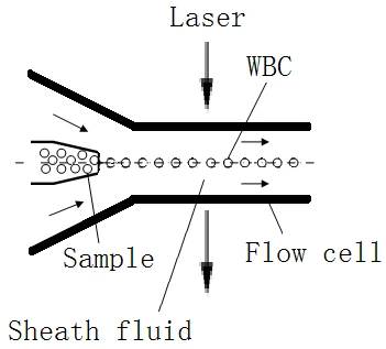
Figure 11 (WBC Measurement)
After a predetermined volume of blood is aspirated and diluted by a certain amount of reagent, it is injected into the flow cell. Surrounded with sheath fluid (diluent), the blood cells pass through the center of the flow cell in a single column at a faster speed. When the blood cells suspended in the diluent pass through the flow cell, they are exposed to a laser beam. The intensity of scatter light reflects the blood cell size, complexity of cell nucleus, and granularity respectively. The low-angle scattered light reflects cell size, and the high-angle scattered light reflects complexity of the cell nucleus, and the side-angle scattered light reflects granularity respectively. The optical detector receives this scatter light and converts it into electrical pulses. Pulse data collected can be used to draw two 2-dimensional distributions (scattergrams). As shown in Figure 3-2 , X-axis represents the intracellular density and Y-axis the blood cell size. Various types of analysis data can then be obtained from the scattergrams.
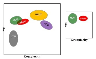
Figure 12 (DIFF channel scattergram)
By analyzing the DIFF channel scattergram, the analyzer presents the Neu%, Lym%, Mon%, Eos% and Baso%.
3.4.2 Electrical Impedance Method
WBCs are counted and sized by the Electrical Impedance method. This method is based on the measurement of changes in electrical resistance produced by a particle, which in this case is a blood cell, suspended in a conductive diluent as it passes through an aperture of known dimensions. An electrode is submerged in the liquid on both sides of the aperture to create an electrical pathway. As each particle passes through the aperture, a transitory change in the resistance between the electrodes is produced. This change produces a measurable electrical pulse. The number of pulses generated signals the number of particles that passed through the aperture. The amplitude of each pulse is proportional to the volume of each particle.
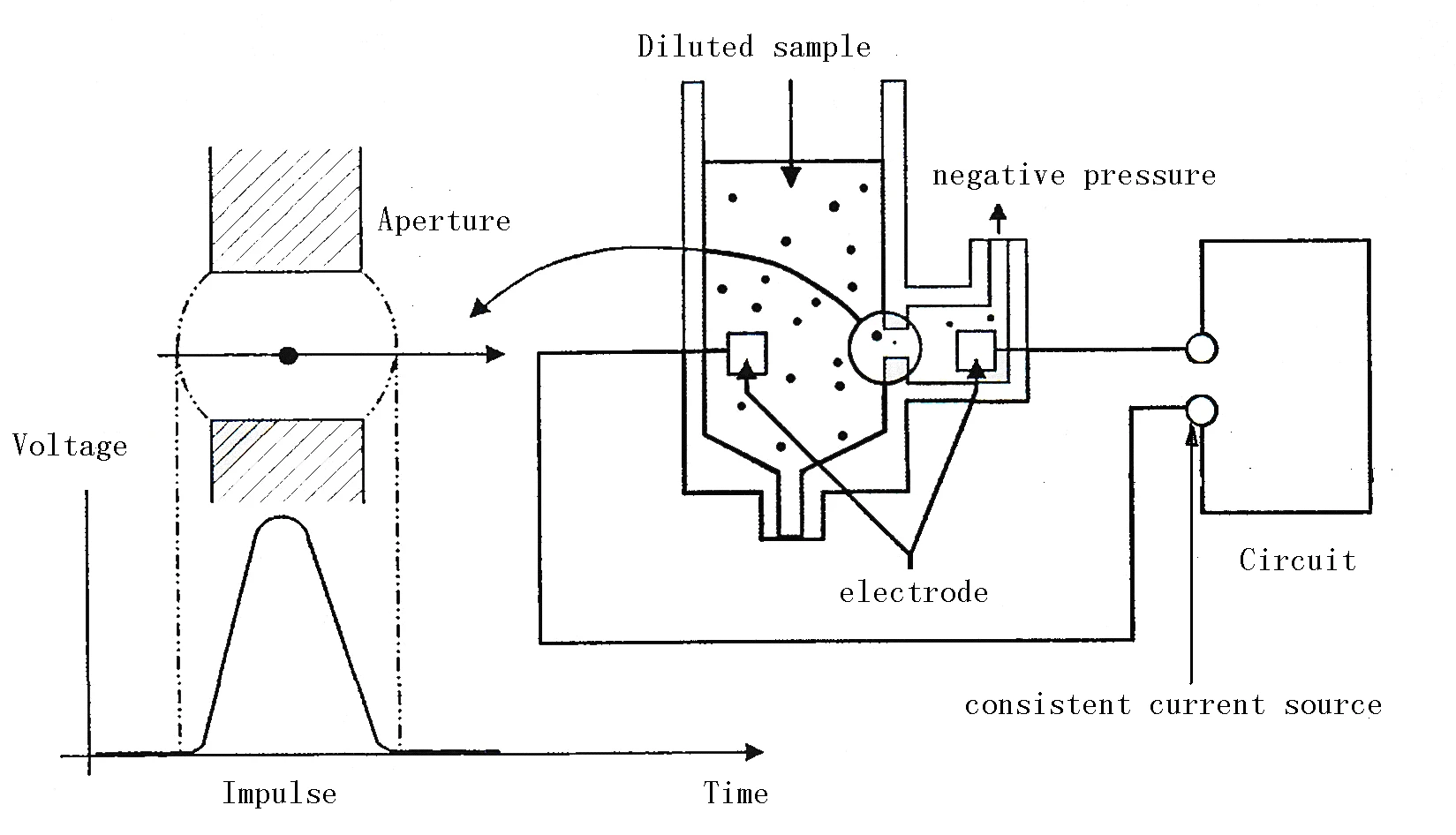
Figure 13 (Electrical Impedance method)
Each pulse is amplified and compared to the internal reference voltage channel, which only accepts the pulses of a certain amplitude. If the pulse generated is above the WBC lower threshold, it is counted as a WBC. The analyzer presents the WBC histogram, whose x-coordinate represents the cell volume(fL)and y-coordinate represents the number of the cells.
3.5 RBC/PLT Measurement
3.5.1 Electrical Impedance Method
RBCs/PLTs are counted and sized by the Electrical Impedance method. This method is based on the measurement of changes in electrical resistance produced by a particle, which in this case is a blood cell, suspended in a conductive diluent as it passes through an aperture of known dimensions. An electrode is submerged in the liquid on both sides of the aperture to create an electrical pathway. As each particle passes through the aperture, a transitory change in the resistance between the electrodes is produced. This change produces a measurable electrical pulse. The number of pulses generated signals the number of particles that passed through the aperture. The amplitude of each pulse is proportional to the volume of each particle.
Figure 14 (Electrical Impedance method)
Each pulse is amplified and compared to the internal reference voltage channel, which only accepts the pulses of a certain amplitude. If the pulse generated is above the RBC/PLT lower threshold, it is counted as a RBC/PLT. The analyzer presents the RBC/PLT histogram, whose x-coordinate represents the cell volume(fL)and y-coordinate represents the number of the cells.
3.5.2 Derivation of WBC-Related Parameters
Based on the analysis of the DIFF channel scattergram and the Lym region, Neu region, Mon region and Eos region, the analyzer calculates the Lym%, Mon%, Eos% and Neu%. Having achieved the WBC, the analyzer proceeds to calculate Lym#, Neu#, Mon# and Eos# per the following equations while Bas# is obtained directly by the Electrical Impedance method and expresses them in 109/L.
White Blood Cell count
WBC is the number of leukocytes measured directly by counting the leukocytes passing through the aperture.
Basophils percentage
Bas% = Particles in Base region of Diff channel / Sum of all particles in Diff channel except those in Ghost region * 100%
Lymphocytes percentage
Lym% = Particles in Lym region of Diff channel / Sum of all particles in Diff channel except those in Ghost region * 100%
Neutrophils percentage
Neu% = Particles in Neu region of Diff channel / Sum of all particles in Diff channel except those in Ghost region * 100%
Monocytes percentage
Mon% = Particles in Mon region of Diff channel / Sum of all particles in Diff channel except those in Ghost region * 100%
Eosinophils percentage
Eos% = Particles in Eos region of Diff channel / Sum of all particles in Diff channel except those in Ghost region * 100%
Basophils number
Bas# = WBC * Bas%
Lymphocytes number
Lym# = WBC * Lym%
Neutrophils number
Monocytes number
Neu# = WBC * Neu
Mon# = %WBC * Mon%
Eosinophils number
Eos# = WBC * Eos%
3.6 HGB Measurement
3.6.1 Colorimetric Method
HGB is determined by the colorimetric method. The WBC/HGB dilution is delivered to the HGB bath where it is bubble mixed with a certain amount of lyse, which converts hemoglobin to a hemoglobin complex that is measurable at 535 nm. An LED is mounted on one side of the bath and emits a beam of monochromatic light, whose central wavelength is 535nm. The light passes through the sample and is then measured by an optical sensor that is mounted on the opposite side. The signal is then amplified and the voltage is measured and compared to the blank reference reading (readings taken when there is only diluent in the bath), and the HGB is measured and calculated in the analyzer automatically.
3.6.2 HGB
The HGB is calculated per the following equation and expressed in g/L.
HGB(g/L) = Constant * Blank Photocurrent / Ln
4. Installing your analyser
4.1 Introduction
Installation by personnel not authorized or trained by the Manufacturer may cause injury or damage to your analyzer. Do not install your analyzer without the presence of Manufacturer-authorized personnel.
Your analyzer is tested before it is shipped from the factory. International symbols and special handling instructions tell the carrier how to treat this electronic instrument. When you receive your analyzer, carefully inspect the carton. If you see any signs of mishandling or damage, contact the Manufacturer customer service department or your local distributor immediately.
4.2 Installation Requirements
4.2.1 Installation Requirements
Check the site for proper space allocation. In addition to the space required for the analyzer itself, arrange for
• at least 100 cm on each side, which is the preferred access to perform service procedures.
• at least 50 cm behind the back side for cabling and ventilation.
• enough room on and below the countertop to accommodate the diluent and waste containers.
4.2.2 Power Requirements
• Make sure the analyzer is properly grounded.
• Before turning on the analyzer, make sure the input voltage meets the requirements.
• Using a plug-board may bring electrical interference and the analysis results may be unreliable. Please place the analyzer near the electrical outlet to avoid using the plug-board.
• Please use the original electrical wire shipped with the analyzer. Using other electrical wire may damage the analyzer or cause unreliable analysis results.
Voltage | Input power | Frequency | |
Analyzer | A.C. 100V-240V | 300 VA | 50/60 Hz |
Table 5
4.2.3 General Environment
• Operating temperature:15°C - 30°C, Optimal operating temperature: 15°C - 30 °C
• Optimal operating humidity: ≤ 85 %
• Operating atmospheric pressure: 70 kPa - 106 kPa.
• The environment should be as free as possible from dust, mechanical vibrations, loud noises, pollution and electrical interference.
• It is advisable to evaluate the electromagnetic environment prior to operation of this analyzer.
• Do not use this analyzer in close proximity to sources of strong electromagnetic radiation (e.g. unshielded intentional RF sources), as these may interfere with the proper operation.
• Do not place the analyzer near brush-type motors, flickering fluorescent lights, and electrical contacts that regularly open and close.
• Do not place the analyzer in direct sunlight or in front of a source of heat or drafts.
• The environment should be good ventilation.
• Do not place the analyzer on a slope.
• The analyzer is not waterproof.
4.2.4 Transport and Installation
• Transport or installation by personnel not authorized or trained by the Manufacturer may cause injury or damage to your analyzer. Do not install your analyzer without the presence of Manufacturer-authorized personnel.
• To avoid damage during the transportation, the sampling assembly of the analyzer is fixed with a plastic cable tie and a clamp. Do remove them before using the analyzer.
The transport and installation shall be conducted by Manufacturer-authorized personnel. Do not transport or install the analyzer without contacting our customer service department or your local distributor.
5. Start-up
5.1 Introduction
The BDL-6701 is a flexible laboratory instrument that can be tailed to your work environment. You can use the " Setup" program to customize the software options as introduced in this chapter.
The analyzer divides the operators into two levels, common user and administrator. Note that an administrator can access all the functions open to a common user. This chapter introduces how to start and customize your analyzer respectively as a common user level and as an administrator.
5.2 Precautions before Power-on
Before you power on the analyzer each time, pay attention to the following to ensure the system is ready:
Reagents
You should use the reagents designated by the Manufacturer and store and use them strictly according to the instructions of the reagents.
Before using the analyzer, check that the reagents are connected correctly.
Before use, ensure the reagent bottles or containers have adequate reagents.
Waste Liquid Container
Check whether the waste liquid container is full. It is suggested to empty the waste liquid container before powering the machine.
Liquid Tube
Check whether the reagent and waste liquid tubes are bent and whether the connection is reliable.
Power Supply
Check whether the power plug of the analyzer has been fully inserted into the power socket.
5.3 Logging on System
1. Turn on the power of the analyzer.
2. Check that the indicator on the analyzer is lit up.
After the software is started, the login dialogue box will be popped up, as shown in the figure below:
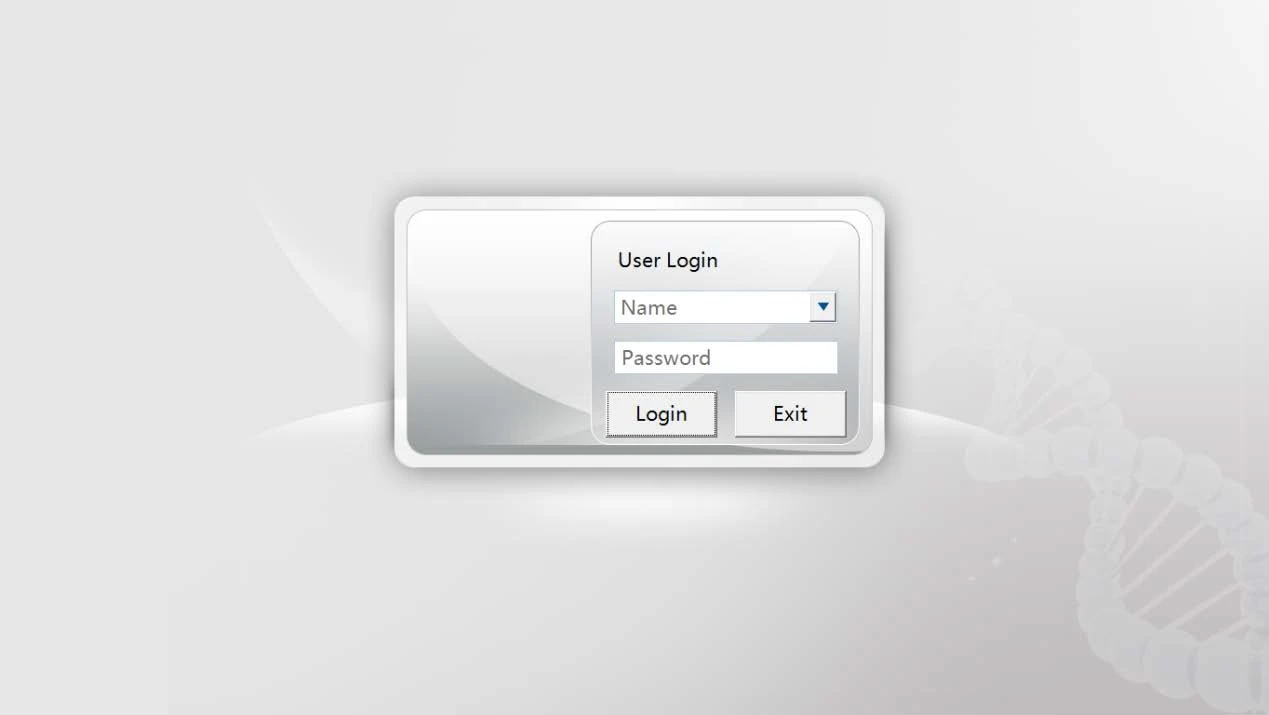
Figure 15
The initial administrator username and password are "admin".
1. Input the correct username and password and click the "Login" button, and the analyzer will execute the startup initialization operation, as shown in the figure below:
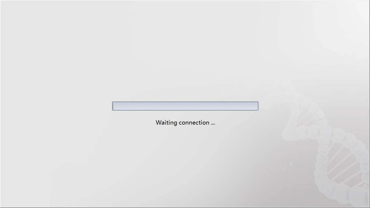
Figure 16
2. During the initialization, the cleaning and blank test will be performed. When the blank test is ended, the system will enter the sample analysis interface and display the result of the blank test, as shown in the figure below:
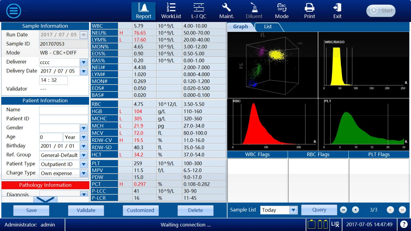
Figure 17
For the blank test, only the test values of WBC, RBC, HGB, HCT, and PLT are
displayed. The acceptable range is as follows:
Parameter | Limits |
WBC | ≤ 0.2 x 10⁹ / L |
RBC | ≤ 0.02 x 10¹²/ L |
HGB | ≤ 1g / L |
HCT | ≤ 0.5% |
PLT | ≤ 10 x 109 / L |
Table 6 (Acceptable Limits of Blank)
5.4 System Setup
The analyzer has been initialized before leaving the factory. You can set some parameters to meet the different needs, in order to ensure the safety of setup and data, the analyzer divides the operators into administrators and common users and opens different setup functions for different user authorities. Administrators have higher authority than common users and can set more items.
5.4.1 Ref. Range
Click the  button on the screen, and then select "Setup""Ref.Range" on the pop-up menu to enter the interface.
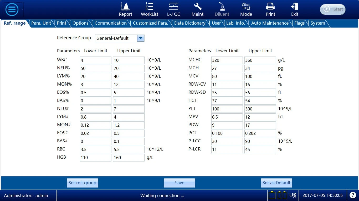
Figure 18
The range of normal values is the range of reference values based on different
normal groups. If the analysis result is out of the range of normal values, this will be deemed clinical abnormality. On the interface and the printed report, "H" indicates the analysis result is higher than the upper limit of the range of normal values; "L" indicates lower than the lower limit.
The analyzer has general default, man, woman, child, infant, neonate, and 10 customized reference ranges. The default setting is "General default,". You should select appropriate reference groups according to the actual situation of the samples and set appropriate range of reference values.
From the Population Classification dropdown box, select the class to be set, and the software will automatically read the corresponding setting. The default upper and lower limits of customized reference ranges are 0. In the edit box, input the corresponding values and click the "Save" button to save the current settings.
To check the information on the range of reference values or modify the name, age range and gender of a user-defined reference group, click the "Set Reference Group" button to open the Reference Group Setup dialogue box, as shown in the figure below:
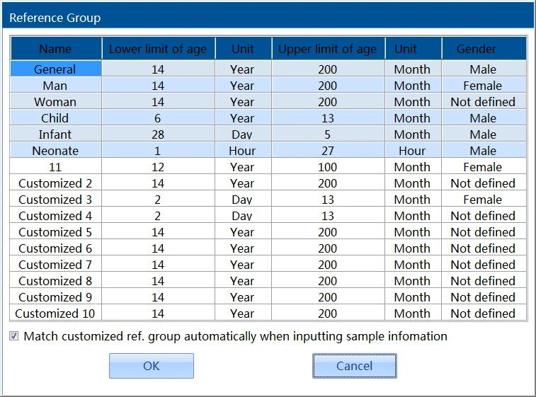
Figure 19
The reference group name and other information of the 6 fixed reference
groups in the list of reference groups can't be modified. You can modify the name, age range, and gender of the 10 customized reference groups as needed.
(1) The reference group name must not be empty.
(2) The name of a customized reference group must not be the same as that of any fixed reference group, and the names of the customized reference groups must be different from each other.
If "Automatically match customized reference groups according to the gender
and age" is not selected, when the sample information is inputted, the system will automatically select one of the fixed reference groups according to the gender and age. Otherwise, the system will select a matched group from the fixed reference groups and customized reference groups, and you do not need to input the information manually.
5.4.2 Units
Click the  button on the screen, and then select "Setup" "Para. Unit" on the pop-up menu enter to the interface.
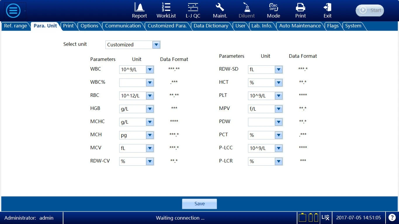
Figure 20
This analyzer provides 3 fixed units and 1 customized unit. You can directly
select fixed units or define the units of the parameters according to the actual needs. The units of all modules of the system are set here.
For other options except "Customized", the units of the parameters can be viewed only and can't be modified. If "Customized" is selected, the units of the parameters can be modified. Click the "Save" button to save the user-defined unit settings.
5.4.3 Print
Click the  button on the screen, and then select "Setup""Print" on the pop-up menu to enter the interface.
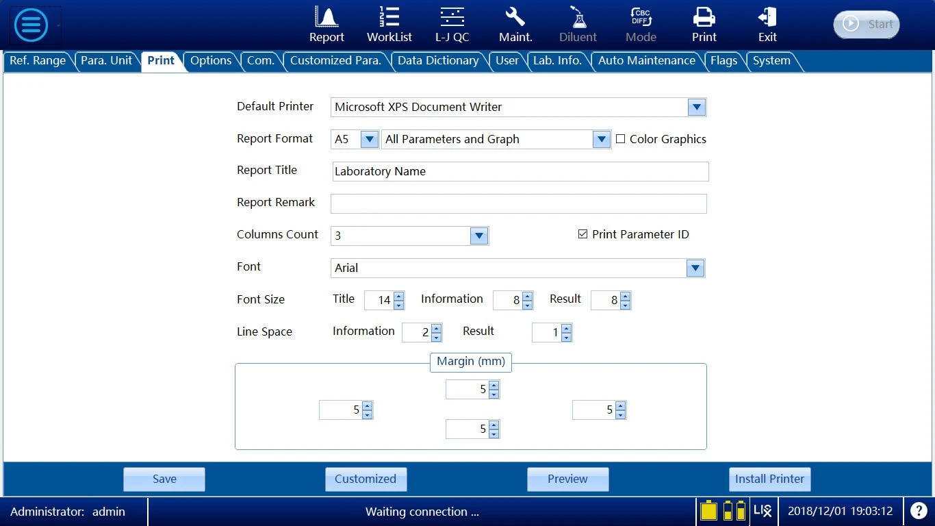
Figure 21
Default Printer
The default printer will be used for the printing for all modules. If you have modified the default printer in the operation system, the printer name in this combo box will change. At the same time, if the printer is modified here, the default printer in the Windows OS will also change.
Format of Report
For report printing, A4 and A5 are supported. The formats include
1. A4 all parameters with graphs; 2. A4 all parameters without graphs; 3. A5 all parameters with graphs; 4. A5 all parameters without graphs. "All parameters" means all parameters measured by the analyzer are printed. "With graphs" means histograms and scattergrams are printed. "Color Graphic" means the graphics in report are colorful.
Reporting Title
The name of the unit printed on the report heading.
Remarks of Report
Printed in the bottom left corner of the report to explain the report.
Font Size
"Title F" is used to set the font size of the heading of the report to be printed; "Parameter" is used to set the font size of the sample parameters name fields and inspection information fields; "Item" is used to set the font size of the test parameters and results.
Line space
The space height between lines of report.
Customized
Click the "Customized" button to open the following dialogue box :
On the Sample Information tab, the fields and sequence of printing of the
report can be set. The items added to the right list are the printing items, and the printing sequence is from top to bottom. On the Result tab, the number and sequence of printing parameters can be set. The number of parameters of each template and their sequence on the report are adjustable.
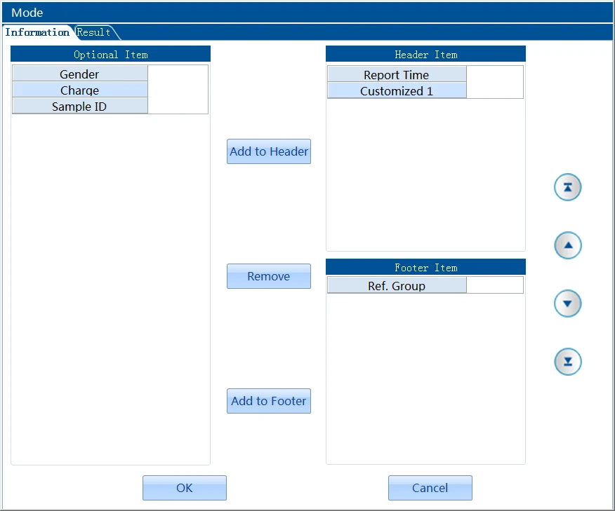
Figure 22
On the Sample Information tab, the fields and sequence of printing of the
report can be set. The items added to the right list are the printing items, and the printing sequence is from top to bottom. On the Result tab, the number and sequence of printing parameters can be set. The number of parameters of each template and their sequence on the report are adjustable.
5.4.4 Options
Click the  button on the screen, and then select "Setup""Options" on the pop-up menu to enter the interface.
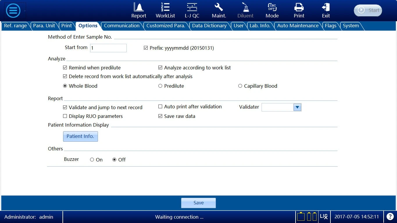
Figure 23
• Method of Entry Sample No.
The start sample number of each day can be set, with the default of 1. The sample number for the day is the last sample number plus 1. To use a date prefix, tick the Use Prefix option. An example of the sample number format is "20150131". By default, this option is not ticked.
• Remained when Pre-diluted
In the sample analysis, if the blood sample mode is Pre-diluted, when the analysis is going to begin, the system will prompt whether to analyse in the Pre-diluted mode. If you select "Yes", the analysis in the Pre-diluted mode will begin; if you select "No", no operation will be executed.
• Analyze according to Worklist
If this option is selected, the analysis will be performed according to the sample information input in the worklist. Each sample newly analyzed matches the entry "To be Run" in the worklist.
• Delete record from work list automatically after analyzation
If "Analysis according to Worklist" is selected, when the sample analysis is ended, the corresponding sample entry in the worklist will be deleted automatically.
• Default Sample Type
Set the initial sample type when the analyzer is powered on and enters the Sample Analysis interface.
• Validate and jump to next record
If this option is selected, after the sample is verified on the Details
Review interface, the system will automatically display the next sample not verified.
• Verifier
When you enter the interface for the first time after installing the software, if you have the verification authority, the field will display your username by default; otherwise, it will display the username of the first operator with verification authority in the User Management list by default.
The dropdown list displays all usernames with verification authority set on the User Management interface. After the settings are saved, if you have the verification authority, when the verification operation is executed successfully, the Verifier field will display your name set here; otherwise, the username in the login dialogue box popped up will be displayed.
• Display research use parameters
If this option is selected, when the sample analysis is ended, you can click the "RUO" button to open the Research Use Parameters interface to view the result of the research use parameters.
• Patient Information
Select patient information you wanted display and edit.
• Buzzer
After the Alarm Buzzer is started, the buzzer in the analyzer will give
alarm sound in case of alarm; if the Alarm Buzzer is turned off, the buzzer will not give alarm sound.
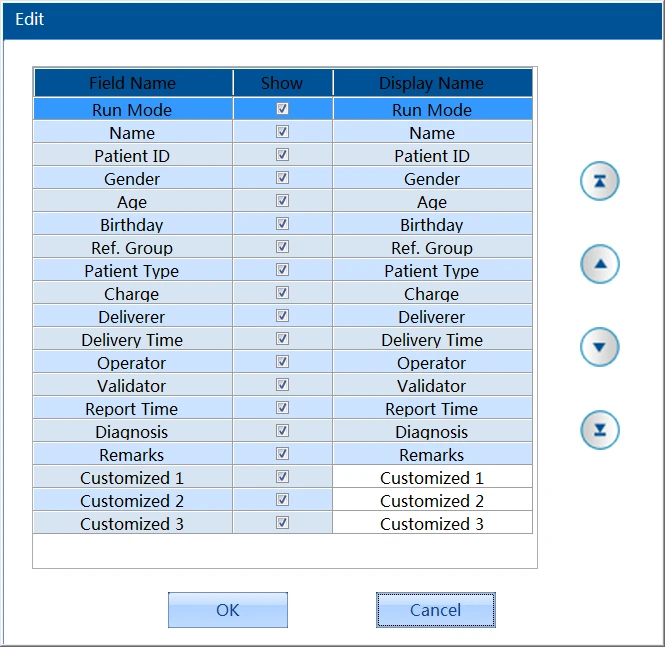
Figure 24
5.4.5 Communication
Click the  button on the interface, and then select "Setup" "Communication" on the pop-up menu to enter the interface.
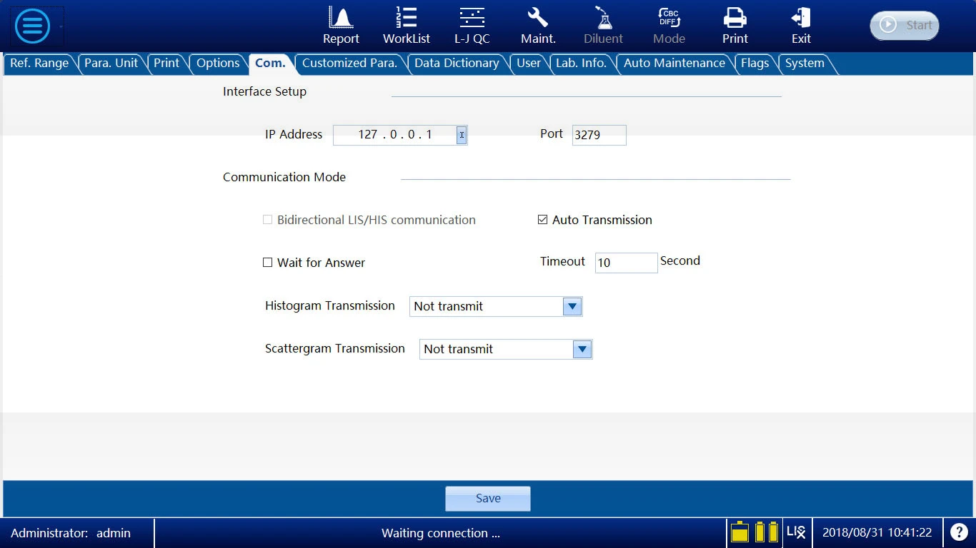
Figure 25
• Interface Setup
The "IP Address"and "Port" are the IP and port of LIS server. The setting should correspond to the server's setting.
• Communication Mode
If "Auto Transmission" is checked, the results will be sent automatically when analyses of samples are finished.
If "Wait for Answer" is checked , a response is supposed when a message is
sent to LIS server. "Timeout"is the maximum time to wait for the response.
If "Transmit as a bitmap file"is selected, the histograms picture of analyses will be sent to LIS server.
• Save
Click "Save"button to save the setting .
5.4.6 Customized Para.
Click the  button on the interface, and then select "Setup""Customized Para." on the pop-up menu to enter the interface.
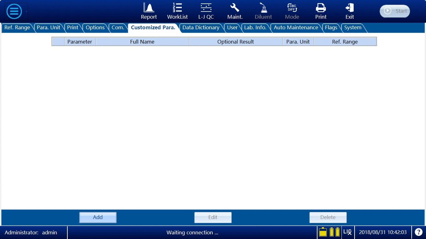
Figure 26
Customized Parameters are the items that can be analyzed through other methods . They can be inputted into the system and printed in the same report with the results generated by the Auto 5-part Hematology Analyzer.
Click "Add"button ,the editing interface will be displayed.
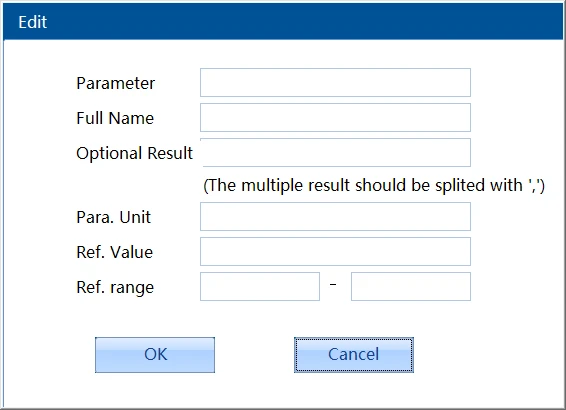
Figure 27
"Optional Result"is a series of results which are divided by comma. In the Input interface of Customized parameters , the optional results will be listed in a combo box. Operator can select a result instead of
inputting manually.
"Ref. Value" and "Ref. range" are alternatives. For a quantitative parameter, a "Ref. range" is proper . On the contrary, for a qualitative parameter, a "Ref. Value" will be more reasonable.
Edit
Click the record you want to edit, then click the "Edit" button. The editing interface will be displayed. After the information has been modified, click the "OK" button to save the modification.
Delete
Click the record you want to delete, then click the "Delete" button. The record will be deleted.
5.4.7 Data Dictionary
Click the  button on the screen, and then select "Setup"" Data Dictionary" on the pop-up menu to enter the interface.
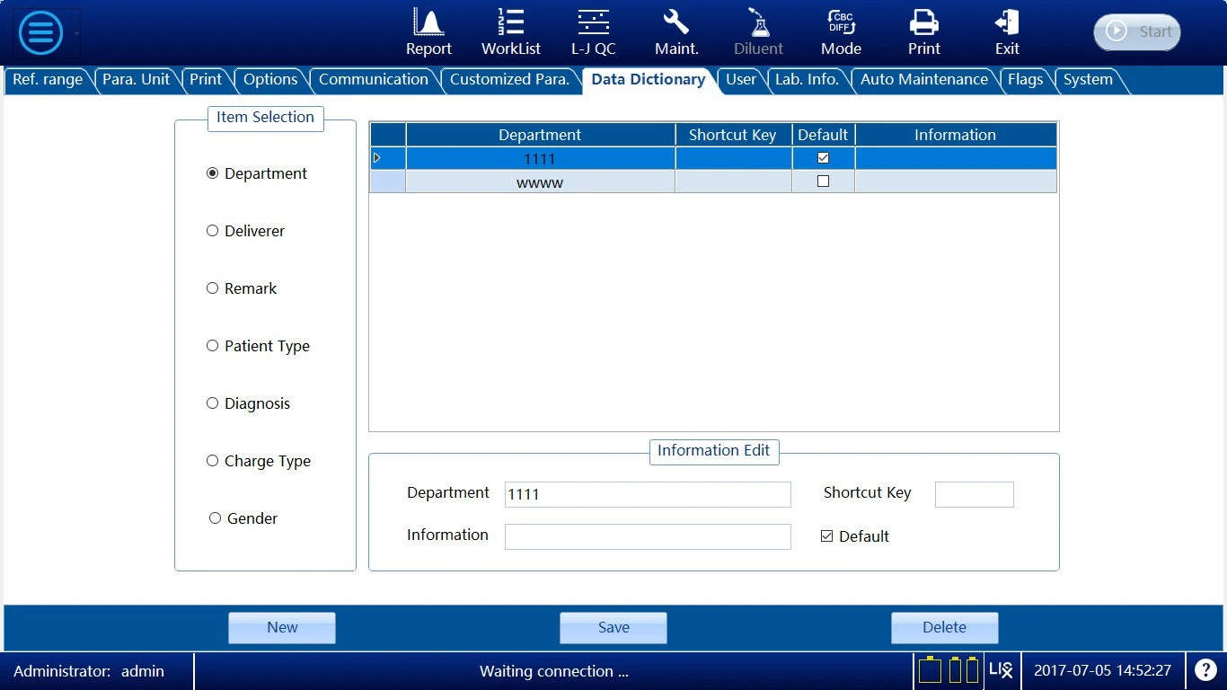
Figure 28
Click "New "button then input the field name, shortcut code, and note
in the fields of "Edit Information". If "Default" is selected, before the sample information is input, the default set will be displayed in the corresponding field. It is suggested to use numbers and letters or their combination to form a shortcut key. The remarks information can be empty.
Save
When an item is selected, the information on this item can be modified. Click "Save"button to save the edited item .
Delete
When an item is selected, this item can be deleted, and the sample information fields input for this item will also be deleted.
5.4.8 User Management
Click the  button on the screen, and then select "Setup""User" on the pop-up menu to enter the interface.
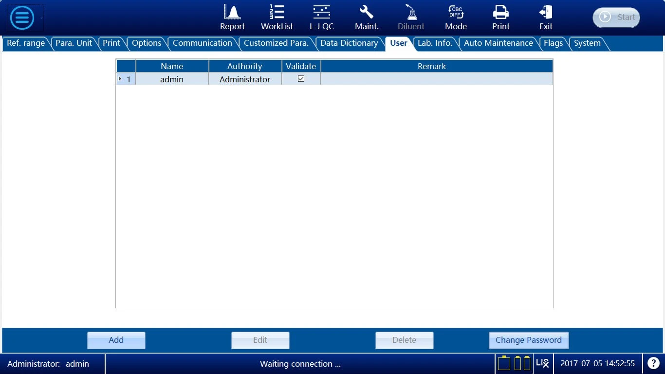
Figure 29
The "Add" function is used to add users. Click the "Add" button to open the following Add User dialogue box :
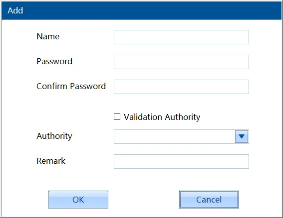
Figure 30
Input the contents in the edit box, click the "Authority" combo box, and set the authority of the new user to "Common User" and "Administrator". Click "OK" to save the settings or "Cancel" to directly exit.
Edit
In the user list, click the user cell to be modified. Click the "Edit" button to pop up the following dialogue box :
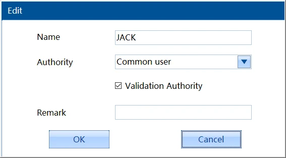
Figure 31
You can modify your username and authority as needed. Click the "OK" button to save the user information modified.
Delete
In the user list, select a user line and click the "Delete" button to pop up the confirmation dialogue box. After you click "OK", the current user will be deleted.
Change Password
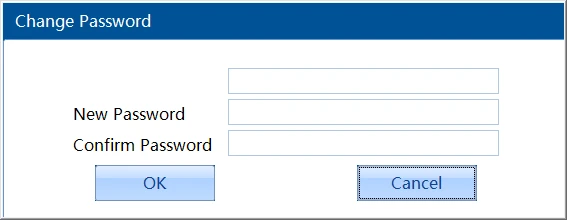
Figure 32
"Change Password" is used to change the password of the current
user. Input the old password of the user correctly, input the new password, click "OK", and the system will prompt "The password has been changed".
5.4.9 Lab Information
Click the button on the screen, and then select "Setup""Lab Info." on the pop-up menu to enter the interface.
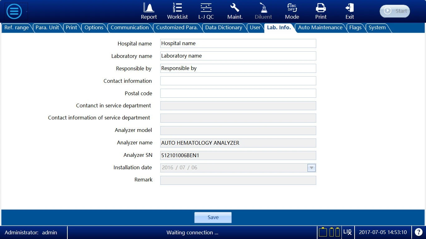
Figure 33
Save
Click the "Save" button to save the information.
5.4.10 Auto Maintenance
Click the  button on the screen, and then select "Setup"" Auto Maintenance" on the pop-up menu to enter the interface.
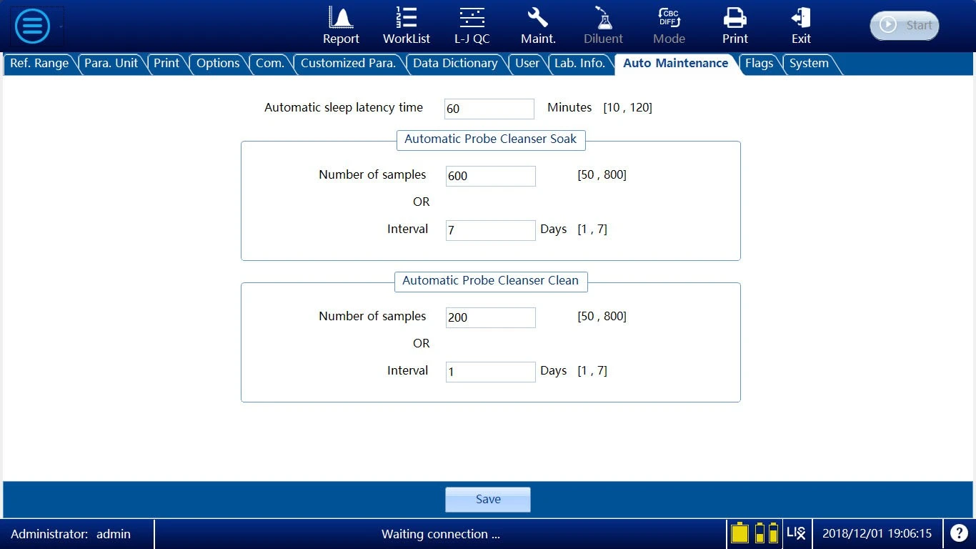
Figure 34
Automatic sleep latency time
When there is no action of the fluidics, the analyzer will enter the sleep mode acco