
Get Price
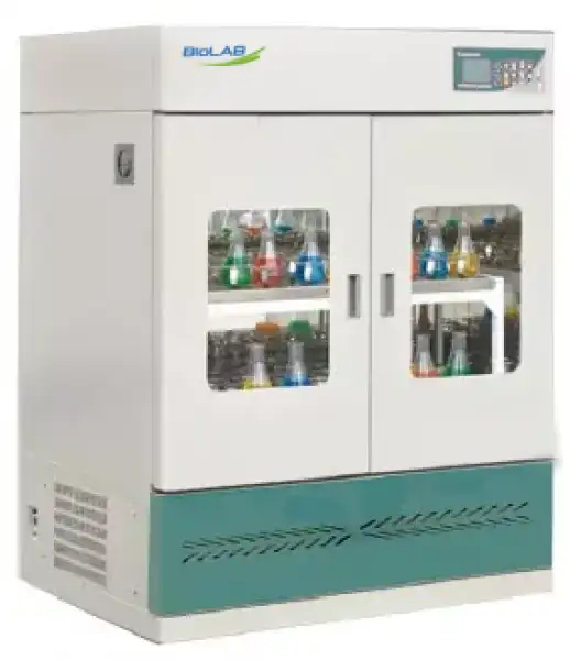
Floor Standing Shaking Incubator BER-2702
- 1. Imported compressors, imported bearings, servo motors.
- 2. Air duct design, not direct blowing, good temperature uniformity.
- 3. The minimum speed is 10rpm.it can start and stop at ultra-low speed to protect the sample.
- 4. Make an appointment to start the function.
- 5. Solenoid valve defrost function can ensure long-term low temperature operation.
- 6. Can be set to run forward, reverse, and alternately run.
- Up to 3-Year Product Warranty
- US & EU Compliance Standards
- Door-to-Door Shipping
Technical Specifications
Detailed operating and construction parameters for this model.
| Model | BER-2702 |
| Control Mode | PID microcomputer processing chip |
| Cycle Mode | Forced convection |
| Shaking Mode | Convolution |
| Display Mode | LCD liquid crystal display |
| Drive Mode | Multidimensional drive |
| USB data download system | |
| Control System | Standard mode; continuous mode; programmable mode |
| Rotary Speed Range (rpm) | 0, 20-350 (Can do static training, forward and reverse) |
| Rotary Accuracy (rpm) | ±1 |
| Amplitude (mm) | Φ26 |
| Max Capacity (clamp) | 100ml*60 or 250ml*38 or 250ml*22 or 1L*16 |
| Max Capacity (stick mat) | 100ml*60 or 250ml*36 or 500ml*24 or 1L*16 |
| Standard configuration | 250ml*24 |
| Plate Size (mm) | 500*360 |
| Timer Range (h/min) | 0-9999 (with timing function, continuous operating) |
| Temperature Range (°C) | 4-65 (25°C) |
| Temperature Accuracy (°C) | ±0.1 |
| Temperature Uniformity (°C) | ±0.5 (37°C, Effective Working Area) |
| Temperature Motion (°C) | <0.1 (37°C) |
| Tray Quantity | 2 (pieces) |
| External Size (mm) | 700*580*1280 |
| Capacity (L) | 175 |
| Power (W) | 850 |
| Power Supply | AC220 ± 10% 50-60HZ |
| Ambient Temperature (°C) | 5-30 |
| Additional Function | Ultra-low start, adjustable start speed, automatic overspeed protection, watchdog timer, parameter memory, call recovery, refrigeration unit overload protection and call delay start, automatic defrost, upper and lower limit temperature sound and light alarm, automatic stop when the door is opened (optional), with lighting, ultraviolet disinfection function (optional), setting parameter view, monitoring temperature and correction of ambient temperature. Touch screen (optional) |
Product Features
Key design, performance, usability, and safety advantages.
Operating Manual View instructions, operating procedures, safety information, and maintenance guidance.
1. Please do abide by the safety precautions
1.1 Do not damage the power line
1.2 Matters and attention
2. The installation before using
2.1 The position of the instrument
2.2 Fix the footings
2.3 The use of water box of the refrigerator before using
3. Operation Overview
3.1 Introduction to Control Panel
3.2 Setting of speed, temperature and time
3.3 Query of set value
3.4 Start and stop
3.5 Pause
3.6 Setting of booking function
3.7 Setting of timing mode
3.8 Setting of timing unit
4. Setting of rotating direction
5. Setting of door control functions (optional)
6. Setting of lighting and sterilizing function (except water bath shaker)
7. Setting of call memory function
8. Parameter password table
9. The downloading function of USB data
10. Data reading method
11. The adjustment of amplitude
12. Simple malfunctions and the ways of eliminating
13. After-sale service
1. Please do abide by the safety precautions
To pretend yourself or others from being injured or financial damage, please do pay attention to the safety matters.
Prohibited items
1.1 Do not damage the power line
2. Non-professional serviceman is not allowed to open the power supply unit door of the equipment
3. Do not put your fingers or objects into the air hole
4. Do not leave the equipment on the furnace or under the sun
5. It is prohibited to leave the living animals inside the incubator
6. Do not touch the attaching plug with wet hands
7. Please use independent power supply, do not use the power beyond the limit, all-purpose socket or connecting service in case the power line overheating
1.2 Matters and attention
1. Before using the product, please do read carefully the operating instruction
2. Please read carefully the safety tips, matters and attention of the operating instruction
3. Before starting the equipment, please do install the two footings of the equipment in line with the instructions of the operating instruction
4. Please abide by the operations below for the sake of protecting the compressor to work under normal conditions.
1. The inclination angle should be less than 45 degree when moving the machine
2. After moving the machine of full temperature function, please shut down the machine and close refrigeration, or leave it be for 24 hours before starting the equipment again.
3. When setting temperature (indoor temperature plus 10 degree) closing and starting the equipment, make sure the interval time of the two times' setting temperature and starting time more than ten minutes
4. The equipment must be grounded firmly. Without installing grounding device, inductive static might be caused on the metal case
5.Before using, please confirm the local supply voltage
6.Under the following cases, the attaching plug must be plucked off
1. When starting the power box door of the equipment and draft damper
2. When changing the fuse
3. When malfunction occurs, and it cannot be used
4. When the equipment has not been used for long time
5. When moving the equipment
8. The equipment should be placed on firm and steady surface, and make sure it on level condition
9.There must be 40cm interspace around the equipment
10. If there is refrigeration function and need continuous refrigeration, one time of heating eliminating damp process every ten days
11. If there is refrigeration function, one time of cleaning the dusts on the condenser beside the compressor every half a year
12. If the experimental vessels are broken, take down the wobble place immediately, and clean up the liquid and residual glass
13. If experimental samples flow into the controlling panel, it also can cause the circuit abnormal
14. Examinations should be made often of the flask clamp to fix the screws in case the falling off of the clamps
15. Do not open the equipment at will, or it will affect the constant temperature effects
16. It is forbidden for the coating of the equipment case to meet with gas, banana oil and other volatile chemicals
17. If the power line is damaged, special accessories of the company shall be used only
18. Keep it clean inside and outside the box; always clean up sundries and stains
19. Starting forcedly, closing on and off the equipment door is easily to cause the damage of the equipment
20. Before starting the equipment door, confirm if the rocker is under idle state
21. When plugging the attaching plug of the power supply, do not pull the power line directly.
2. The installation before using
2.1 The position of the instrument
1. The instrument should be placed on firm surface, as is shown under the left picture
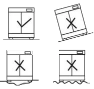
Figure 1
2. Leave a certain space around the equipment, as shown below
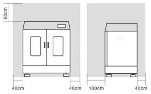
Figure 2
2.2 Fix the footings
1. Four footings is shown in picture one, one of which is shown in picture two
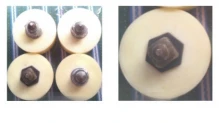
Figure 3
2. Installation procedures (the operation is only limited to vertical incubator shaker and horizontal incubator shaker except table type incubator shaker, as only the front footing needs adjusting for able type incubator shaker
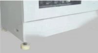
Figure 4
Step one: place the equipment to the appointed place, fix respectively the four footings, and make sure the footings and installation holes rightly. As shown in the picture
Step two: adjust the footings: when the four footings are fixed respectively, turn the adjustable foundation of the footing to make it touches the ground firmly, respectively turn the other footings by hand to make sure they touch the ground firmly, cannot be run. As shown in picture three
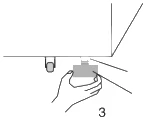
Figure 5
Step three: Debugging on power
After installation, start the equipment to set the temperature, time, rotating speed. When the equipment operates smoothly, observe the four footings if they are shaking; if without shaking, lock the four lock nuts; if it does, go on adjusting until the footings is steady. As shown in below picture

Figure 6
Position of right one, position or right two, adjustable of the left one, position of left two
2.3 The use of water box of the refrigerator before using
The water box is just as shown in the picture
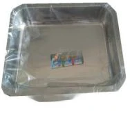
Figure 7
Condensate water box
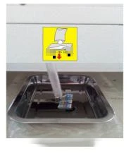
Figure 8
machine condensate water exit
Installation position: condensation box is placed right under the mark of condensate water exit, and place the pipe in the condensation box
2.3.1 Please clean the water box regularly in case the water overflow from the box.
Name | vertical constant temperature shaker (LCD) | |||||
Model | BER-2701 | BER-2702 | BER-2703 | BER-2704 | BER-2705 | BER-2706 |
Control Mode | PID microcomputer processing chip | |||||
Cycle Mode | Forced convection | |||||
Shaking Mode | Convolution | |||||
Display Mode | LCD liquid crystal display | |||||
Drive Mode | Multidimensional drive | |||||
3 Axes | 4 Axes | |||||
USB data download system | Yes(optional) | |||||
Control System | (Standard mode; continuous mode; programmable mode (multi-stage temperature, speed, time control)) | |||||
Rotary Speed Range(rpm) | 0,20-350(Can do static training, forward and reverse) | 0,20-280(Can do static training, forward and reverse) | ||||
Rotary Accuracy(rpm) | ±1 | |||||
Amplitude(mm) | Φ26(customizable Φ35(20-250rpm/min)Φ50(20-2000rpm/min) | |||||
Max Capacity (clamp) | 100ml*60 or 250ml*38 or 500ml*22 or 1L*16 | 100ml*100 or 250ml*56 or 500ml*44 or 1L*24 | 250ml*90 or 500ml*72 or 1000ml*42 | |||
Max Capacity ( stick mat) | 100ml*60 or 250ml*36 or500ml*24or 1L*16 | 100ml*120 or 250ml*70 or 500ml*44or1L*24 | 250ml*112 or 500ml*76 or 1000ml*42 | |||
Standard configuration | 250ml*24 | 250ml*28 500ml*22 | 250ml*45 500ml*36 | |||
Plate Size(mm) | 500*360 | 710*455 | 950*550 | |||
Timer Range(h/min) | 0-9999(with timing function) | |||||
Temperature Range(°C) | Ambient temp.+5-65 | 4-65(25°C) | Ambient temp.+5-65 | 4-65(25°C) | Ambient temp.+5-65 | 4-65(25°C) |
Temp. Accuracy(°C) | ±0.1 | |||||
Temp. Uniformity(°C) | ±0.5(37°C) | |||||
Temp. Motion(°C) | ≤0.1(37°C) | |||||
Tray Quantity | (2 pieces) | |||||
External Size(mm) | 700*580*1280 | 950*700*1280 | 1200*800*1630 | |||
Capacity(L) | 175 | 335 | 580 | |||
Power(W) | 600 | 850 | 900 | 1150 | 1100 | 1400 |
Power Supply | AC220±10% 50-60HZ | |||||
Ambient Temp.(°C) | 5-30 | |||||
Additional Function | Ultra-low start, adjustable start speed, automatic overspeed protection, watchdog timer, parameter memory, call recovery, refrigeration unit overload protection and call delay start, automatic defrost, upper and lower limit over temperature sound and light alarm, automatic stop when the door is opened (optional ), with lighting, ultraviolet disinfection function (optional), setting parameter view, monitoring temperature and correction of ambient temperature. Touch screen (optional) | |||||
Optional accessories | 1.Holder for 50 ml flasks 2.Holder for 100 ml flasks 3.Holder for 250 ml flasks 4.Holder for 500 ml flasks 5.Holder for 1L flasks 6.Holder for 2L flasks | |||||
Table 1
"A-type energo-efficient"
3. Operation Overview
3.1 Introduction to Control Panel
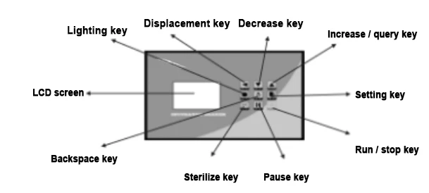
Figure 9
3.1.1 Start up
Turn on the main power switch on the side of the instrument, the temperature display window on the screen shows "PY-3", the speed display window shows "V01", the buzzer makes a short sound and enters the normal display state after 2 seconds.
△IMPORTANT NOTICE: full-temperature shaker (with refrigeration function) requires a longer interval than 10 minutes to start up again. To protect proper use of compressor.
3.2 Setting of speed, temperature and time
1. Press "SETTING" key and "SETTING" identifier lights up. The LCD screen displays in turn "total cycle number Cn", "total segment number Sn", the temperature setting value of the first segment, the speed setting value of the first segment, the time setting value of the first segment, the temperature setting value of the second segment……the temperature setting value of the Sn segment, the speed setting value of the Sn segment, the time setting value of the Sn segment. Click "SETTING" again, or hold "SETTING" to exit the setting interface.
2. To run in constant value mode, press "SETTING" key, set the total cycle number (Cn) to 1 and the total segment number to 1, press the "SETTING" key again to set the temperature, speed and time successively. After setting them, hold "SETTING" key to exit the setting interface.
3. During the setting, press "BACKSPACE" key to return to the previous set value, and "DISPLACEMENT", "INCREASE" or "DECREASE" key can be used to modify the currently displayed set value. Total cycle number and total segment number need to be modified after the machine is shut down.
4. "Total cycle number Cn" is set to hour(s) and in this way the machine will work continuously.
3.3 Query of set value
In the main interface (under running state of the machine), press "QUERY" key and the "INQ" identifier shows the current running cycle and segment. Click "QUERY" key again to display the set value of temperature, speed and time, and then click "QUERY" key to exit and return to the main interface.
3.4 Start and stop
1. After setting, click "RUN stop" key to start the machine, and the "RUN" identifier will light up during operation.
2. Click "RUN stop" key again to stop operation, and the "STOP" identifier will light up during operation.
3.5 Pause
1. When the machine is running, click "PAUSE" key to stop speed and timing function and [speed display window] shows "P-". Click "PAUSE" again to continue operation.
3.6 Setting of booking function
1. When the machine stops running, hold "SETTING" for 3 seconds, and temperature display area shows "LC", speed display area shows password value, enter "36" in password value
2. Click "SETTING" again, and the temperature display area will show "AP", and the speed display area will show set value.
3. Booking function is enabled when set value is 1. Click "SETTING" again to set booking time in minutes.
4. After setting booking time, click "SETTING" to return to main interface. Click "RUN/STOP" and time bar flashes to display booking countdown time.
5. In booking timing, you can change the booking time again with the same method above.
6. When clicking "RUN stop" in booking timing, booking timing will stop, and booking set time will be reset automatically. The booking set time will be reset automatically after power failure.
7. Booking function is disabled when set value is 0.
8. After holding "SETTING" for 3 seconds, exit setting state, automatically save setting value and return to main interface.
3.7 Setting of timing mode
1. Hold "SETTING" for 3 seconds, and temperature display area shows "LC", speed display area shows password value, enter "309" in password value
2. Click "SETTING" again, and the temperature display area will show "ndT", and the speed display area will show set value.
3. The operation is timed when set value is 0; when set value is 1, timing begins after entering constant temperature stage.
4. After holding "SETTING" for 3 seconds, exit setting state, automatically save setting value and return to main interface.
Note: when running stops at the end of timing, the time display area displays "End", and the buzzer sounds. Click "RUN/STOP" to restart operation
3.8 Setting of timing unit
1. Hold "SETTING" for second(s), and temperature display area shows "LC", speed display area shows password value, enter "309" in password value
2. Click "SETTING" again until the temperature display area will show "Hn", and the speed display area will show set value.
3. Timing is expressed in minute when set value is ; and timing is expressed in hour when set value is .
4. After holding "SETTING" for second(s), exit setting state, automatically save setting value and return to main interface.
4. Setting of rotating direction
1. Hold "SETTING" for 3 second(s), and temperature display area shows "LC", speed display area shows password value, enter "303" in password value
2. Click "SETTING" again, and the temperature display area will show "Fr", Speed display area shows set value.
3. The machine works normally when set value is 0; the machine rotates in reverse direction when set value is 1; the machine rotates in both reverse and forward direction when set value is 2.
4. Click "SETTING" again until the temperature display area will show "Fd", and the speed display area will have forward rotation time entered.
5. Click "SETTING" again until the temperature display area will show "P-", and the speed display area will have stop time during reversing entered.
6. Click "SETTING" again until the temperature display area will show "rd", and the speed display area will have reverse rotation time entered.
7. After holding "SETTING" for 3 seconds, exit setting state, automatically save setting value and return to main interface.
Note: the motor rotates in forward direction when both forward and reverse rotation time is set to . (The above operation is modified before starting)
5. Setting of door control functions (optional)
The "OPEN" identifier lights up when the door opens; Otherwise, "OPEN" identifier goes out. If the door is opened during operation, the controller will automatically stop the motor, and when the door switch is closed again, the motor will continue running automatically.
6. Setting of lighting and sterilizing function (except water bath shaker)
1. Hold "SETTING" for 3 seconds, and temperature display area shows "LC", speed display area shows password value, enter "103" in password value
2. Click "SETTING" again until the temperature display area will show "Lt", and the speed display area will have lighting time entered; when Lt=O, delay time is invalid and lighting lamp must be manually turned off.
3. Click "SETTING" again until the temperature display area will show "St", and the speed display area will have sterilizing time entered; when St=O, delay time is invalid and sterilizing light must be manually turned off.
4. After holding "SETTING" for 3 seconds, exit setting state, automatically save setting value and return to main interface.
Note: click Lighting key to enable lighting function; hold Sterilizing key to enable sterilizing function
7. Setting of call memory function
1. Hold "SETTING" for 3 seconds, and temperature display area shows "LC", speed display area shows password value, enter "109" in password value
2. Click "SETTING" again, and the temperature display area will show "Pon", and the speed display area will show set value
3. Call memory function is disabled when set value is ; call memory function is enabled when set value is 1.
4. After holding "SETTING" for 3 seconds, exit setting state, automatically save setting value and return to main interface.
Note: when call function is enabled, the machine will continue running from
the previous running cycle, segment and time at power failure.
8. Parameter password table
Hold "SETTING" for 3 seconds, and temperature display area shows "Lc", speed display area shows password value, enter different password values to set internal parameters, press "SETTING" to modify each parameter. After holding "SETTING" for 3 second(s), exit the setting state and automatically save the parameters.
Operation | Password | Parameter indication | Parameter name | Parameter function | Scope |
Press SETTING key | Lc=103 | Lt | Delay time of lighting lamp is closed | Lighting lamp turns on and turns off automatically after delay for L; when "Lt=0", delay time is invalid and lighting lamp must be manually turned off. | 0~9999min |
St | Delay time of sterilizing light is closed | Sterilizing light turns on and turns off automatically after delay for St. When "St=0", delay time is invalid and sterilizing light must be manually turned off | 0~9999min | ||
Pb | Zero adjustment | Correct the error of sensor generated during measurement (at low temperature). Pb=actual temperature-measured value of instrument | -99.9-99.9°C | ||
PK | Full scale adjustment | Correct the error of sensor generated during measurement (at high temperature). PK=1000* (actual temperature-measured value of instrument)/measured value of instrument | -999-999°C | ||
Lc=109 | Pon | Power-down memory function | 0: none power-down memory function 1: power-down memory function | 0~ 1 | |
Pu | Pause function | 0: pause speed function only 1: pause speed and timing function | 0~ 1 | ||
Lc=36 | AP | Booking setting | 0: enable booking function 1: disable booking function | 0~ 1 | |
T_ | Booking time | When AP is set to 1, click "SETTING" again to set booking time. | 0~ 9999min | ||
Lc=303 | Fr | Selection of motor rotating direction | 0: motor only rotates in forward direction; 1: motor only rotates in reverse direction; 2 motor rotates in both forward and reverse direction. (The motor rotates in forward direction when both forward and reverse rotation time is set to .) | 0~2 | |
Fd | Forward rotation time | Time for motor to rotate in forward direction. | 0 ~ 9999min | ||
P- | Reversing time | Stop time of motor during reversing | 0~9999min | ||
rd | Reverse rotation time | Time for motor to rotate in reverse direction. | 0~9999min | ||
Lc=309 | ndT | Timing mode | 0: timing at the beginning of operation, when running time expires, speed instead of temperature stops. 1: timing at the beginning of operation, end running time expires. Speed and temperature stop simultaneously. 2. timing begins after entering constant temperature stage, when running time expires, speed instead of temperature stops, 3: timing begins after entering constant temperature stage, when running time expires, speed and temperature stop simultaneously. | 0~3 | |
Hn | Timing unit | 0. Timing is expressed in minute; 1:: timing is expressed in hour. Note: this parameter cannot be modified during operation. | 0~1 | ||
Lc=18 | Ht | Ambient temperature | View ambient temperature | Non-modifiable | |
HPb | Ambient temperature correction | Correct the error of ambient temperature generated during measurement; HPb=actual ambient temperature + Ht | -20.0- 20.0°C | ||
Lc=27 | ndf | Defrosting function | 0:close 1:open | 0 or 1 | |
dtl | Defrosting time interval 1 | Defrosting time interval when "time set value" ≤16°C. No defrosting occurs at such segment when dtl=0" | 0-240 hours | ||
Ftl | Defrosting time 1 | Ftl indicates conducting time of solenoid valve when "time set value" ≤16°C | 0- 600s | ||
dt2 | Defrosting time interval 2 | Defrosting time interval when "16°C < time set value" ≤30.0°C. No defrosting occurs at such segment when "dt2=0" | 0-240 hours | ||
Ft2 | Defrosting time 2 | F12 indicates conducting time of solenoid valve when "16°C<time set value" ≤30°C | 0- 600s | ||
Note: parameter indication not involved by water bath shaker includes Lt, st, Dtl, Ftl, dt2, Ft2 | |||||
Table 2
9. The downloading function of USB data
Operation procedures
Under normal condition, long press the key of ▲▼, it shows Lc00
enter password three or nine
Press ▼to enter setting, and enter all the needed numerical values
Press ▼ to shift
After setting, long press ▼ to exit
password | parameter indicating | parameter name | the instructions of the parameter functions | scope |
3 | Y- | year | set the current date year | 00-99 |
N- | month | set the current date month | 00-12 | |
d- | day | set the current date day | 00-31 | |
H- | hour | set the current date hour | 00-59 | |
n- | minutes | set the current date minutes | 00-59 | |
S- | second | set the current date second | 00-59 | |
9 | Ad | address | set the mailing address | 01-16 |
US | function | set the if the USD function is open or not 00:close;01 start | 00-01 | |
Pr | printing function | set the printing function to see if it is open 00:close;01 starts | 00-01 | |
PC | communication | set the PC communication to see if it is open Remarks: when open the PC, USB and printing will auto close | 00-01 |
Table 3
Hint of instruction
If recording data, flash drive cannot be pulled out
If it shows TErr, it means error, and check the communication wire
if it shows URrr, it means error, and check if the flash drive is inserted
If it shows PErr, it means printer error, and check if it connects the printing
After power up, the showed numerical values means the interval time of printing
10. Data reading method
1. Open the "data record guide" CD, find the tool icon  , double-click to install this program.
2. After installation, double-click the icon to open the software.
3. After opening the software, click "confirm"
4. Click "historical data" at upper left corner.
5. Click "select external DAT file", and choose to download files with USB. A dialog box "successfully import data" appears, and then click to confirm.
6. Click curve plotting on the left to draw a graph.
11. The adjustment of amplitude
1. Use the cross screwdriver along with the machine to tear down the rocker
2. Swing the upper plate to the endpoint on the left
3. Insert the positioning pin into the positioning hole on the upper right plate (at this moment, the upper plate cannot swing anymore; otherwise it means the positioning pin is not well inserted.
4. Use the spanner along with the machine to lessen the center bolt, and move the upper plate to the needed place by observing the scale plate
5. Screw the center nut, take out the positioning pin, fix the rocker, and complete the adjustment of swing
6. The maximum swing and the rotating speed can bot be used at the same time
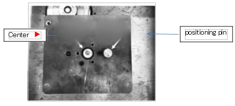
Figure 10
12. Simple malfunctions and the ways of eliminating
phenomenon | cause | elimination |
tray stops turning | external power source is not connected | if the attaching plug is well plugged in; if there is electricity of the socket, if the power switch is open |
the fuse is melted | change the equal fuse | |
tray operates, yet it shows abnormal on the LCD | there might be high-frequency interference within the same line | press the key of setting, it will restore display; eliminate the interference origin in the same line or set a special line, or shut down the main power, and restart in a few minutes |
tray fails to operate, it shows normal on the LCD | bad contact on the door switch(limited to desktop model) | you can connect the two electric wire of the door switch in emergency, and inform our company |
temperature fluctuated widely | open the door too frequently | try to reduce the door opening as much as you can and reduce opening time |
too much noise of the equipment | the instrument is placed evenly | adjust the footing to make the instrument even on the ground |
it gets loose of the multi-hole tray | screw the four footings and tighten the nut | |
it gets loose of the flask clamp | take out the tray, use the tools along with the equipment to tighten the nut of the flask clamp | |
real measures is slightly higher, and often gets over temperature alarm state | the starting temperature is too high | open the air hole of the instrument, if it is used often under low temperature, please carry on drying treatment completely |
Table 4
13. After-sale service
The complete instrument implemented of track service for one year since the date of this instrument is purchased (the purchase invoice shall prevail.)
Within the period of insurance, if malfunctions occur due to manufacturing quality problems, the company shall be responsible for repairing free of charge. After the period of insurance is due, the company undertakes a lifetime maintenance.