
Get Price
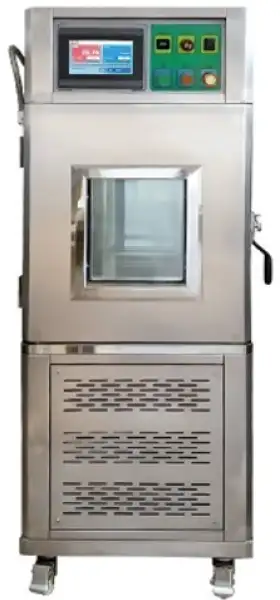
Environmental Chamber BEM-23102
- The rectangular double-layer glass observation window can be used to observe the test product during the test. The observation window has an anti-sweat electric heater device to prevent condensation, and a high-brightness PL fluorescent lamp to keep the interior of the box illuminated.
- It has a test hole for external test power cord or signal line and up and down adjustment of the storage tray.
- The double-layer insulation of the box door is tight and airtight, which can effectively isolate the internal temperature leakage.
- The special temperature rise and fall rate controllable technology realizes the continuous and arbitrary adjustment of the rise and fall rate.
- The compressor circulation system can effectively remove the lubricating oil between the condenser tube and the capillary tube, and the whole series adopts environmentally friendly refrigerant.
- The controller adopts imported LCD display screen, which can display the measured value, set value and time at the same time.
- The controller has multi-segment program editing, humidity and temperature can be controlled quickly (QUICK) or slope (SLOP).
- The built-in mobile sliding transport is easy to move and place and has a strong positioning screw to fix the position.
- Up to 3-Year Product Warranty
- US & EU Compliance Standards
- Door-to-Door Shipping
Technical Specifications
Detailed operating and construction parameters for this model.
| Model | BEM-23102 |
| Capacity | 50L |
| Low Temperature Range | Low temperature: C: -20°C; D: -40°C; E: -60°C |
| High Temperature Range | High temperature: 150°C |
| Humidity Range | 20~98% RH |
| T&H Analytical Accuracy | ±0.1°C, ±1%RH |
| T&H Uniformity | ±1°C, ±2%RH |
| T&H Control Accuracy | ±0.5°C, ±1%RH |
| T&H Fluctuation | ±2°C, ±3%RH |
| Heating/Cooling Rate | Heating: 1~3°C/min (avg.); cooling: 0.7~1°C/min (avg.) |
| Inner &Outer Material | SUS304 |
| Insulation Material | High temperature resistant high-density ethyl chloroformate foam insulation material |
| Cooling System | Air cooling, single compressor: -20~-40°C |
| Air cooling, water cooling, double compressors: -60~-70°C | |
| Safety Protection | No-fuse switch, compressor overload protection switch, refrigerant high/low pressure protection switch, over-humidity and over-temperature protection switch, fuse, fault alarm system |
| Power Supply | AC 220V, 50/60Hz(Standard); 110V, 50/60Hz(Optional, external transformer); Wiring method: air switch |
| Standard Accessory | Observation window, 50mm test hole, PL box light, partition, wet and dry ball gauze, RS232, USB interface |
| Optional Accessory | Operating hole with built-in glass door |
| Internal Size(W*D*H) | 350*350*400mm |
| External Size(W*D*H) | 580*980*1350mm |
| Package Size(W*D*H) | 700*1200*1500mm |
| Net Weight | 180kg |
| Gross Weight | 200kg |
Product Features
Key design, performance, usability, and safety advantages.
Operating Manual View instructions, operating procedures, safety information, and maintenance guidance.
1. Performance
2. System Structure
2.1 Electronic System (Safety Protection System)
2.2 Air Duct System
2.3 Heating System
2.4 Humidification System
2.5 Temperature and Humidity Sensing System
2.6 Water System
2.7 Control System
2.8 Cabinet Material
3. Working Principle
4. Machine Requirements and Utilities
5. Installation Site and Installation Method
6. Power Supply Configuration and Installation Method
7. Precautions Before Use
8. Operation Program
9. Precautions During Operation
10. Maintenance Precautions and Methods
11. Standard Accessories
12. Troubleshooting Examples
13.Revolution procedure
1. Performance
1. Model: BEM-23102
2. Temperature range: 40°C-150°C
3. Humidity range: 20%-98% RH
4. Temperature and humidity control accuracy: ±0.5°C; ±2% RH
Note: The performance guarantee for items 2-4 above requires measurement after the temperature sensing has been stable for 30 minutes.
5. Temperature and humidity distribution uniformity: ±2.0°C; ±3.0% RH
Note: The performance guarantee for item 5 above requires measurement at a position 1/6 of the distance from each wall of the test area, and after the temperature and humidity have been stable for 30 minutes.
6. Internal chamber dimensions: 350 x 350 x 500 mm (W x D x H)
7. External dimensions: 640 x 1000 x 1400 mm (W x D x H)
8. Equipment installation space: at least 147 x 101 x 210 cm (W x D x H)
9. Power supply: AC220V 50Hz
2. System Structure
2.1 Electronic System (Safety Protection System)
a. Zero-crossing thyristor power controllers, 2 sets (one for temperature and one for humidity)
b. Empty-burn prevention switches, 2 sets
c. Water shortage protection switch, 1 set
d. Compressor high-pressure protection switch
e. Compressor overheat protection switch
f. Compressor overcurrent protection switch
g. Quick-acting fuses, 2 pieces
h. No-fuse breaker protection
i. Line fuses and fully shrouded terminals
j. Water shortage alarm
2.2 Air Duct System
a. 90W extended stainless steel shaft.
b. Multi-blade fan to accelerate heat and moisture circulation.
2.3 Heating System
Finned stainless steel electric heating tube.
2.4 Humidification System
EL-type stainless steel humidifying tube.
2.5 Temperature and Humidity Sensing System
Two SUS304 Pt100 sensors are used for dry/wet bulb comparison input. Temperature and humidity are measured through A/D conversion.
2.6 Water System
a. Built-in stainless steel water tank, 20L, 1 piece
b. Automatic water supply device (pumping water from the lower level to the upper level)
c. Water shortage indicator alarm
2.7 Control System
The control system adopts a P.I.D controller and controls temperature and humidity simultaneously.
a. Controller Specifications
Accuracy: temperature ±1.0°C + 1 digit; humidity ±3% RH + 1 digit
Upper and lower limit standby and alarm functions
Temperature/humidity input signal selection: PT100 x 2 (dry bulb and wet bulb)
Temperature/humidity conversion output: 4-20 mA, 6 sets
P.I.D control parameter setting
P.I.D automatic calculation
Dry/wet bulb automatic correction
b. Control Functions
Scheduled start and shutdown function
Date and time adjustment function
2.8 Cabinet Material
Inner chamber material: SUS#304 mirror stainless steel plate
Outer chamber material: imported stainless steel
Insulation material: PU rigid foam + glass wool
3. Working Principle
1. The balanced temperature and humidity control system uses PID mode to control the SSR, so that the heating and humidifying amount of the system equals the heat and moisture loss.
2. The dry/wet bulb temperature signals are converted through A/D and input to the controller CPU. After comparison with the reference value, they are output to the I/O board. The I/O board issues commands to make the air supply system and refrigeration system work. At the same time, the PID controls the SSR, either the heating SSR or the humidifying SSR, so that heat and moisture are uniformly distributed through the air duct system in the test chamber, thereby achieving balanced temperature and humidity control.
4. Machine Requirements and Utilities
Power supply: AC220V 3.5KW/50Hz MAX A
Note: Ensure that the voltage and frequency fluctuation range for the performance of this equipment is: voltage ±5%; frequency ±1%.
Humidification water: Must use pure water or distilled water (the first preparation amount must be more than 20L), or water with conductivity below 10 μs/cm.
Note: Ensure that this water source is as clean as possible. Groundwater is prohibited.
5. Installation Site and Installation Method
1. The installation position should take into consideration the heat dissipation efficiency of the machine and easy inspection and maintenance.
2. The bottom of the machine contains the refrigeration system, and the heat is relatively large. Therefore, during installation, there should be at least 60 cm of distance between the machine body and walls and other machines to ensure smooth ventilation.
3. Install on flat, vibration-free ground. Adjust the four leveling feet at the bottom of the machine body so that the machine is level, so as to facilitate drainage from the inner chamber and prevent abnormal noise. Please check with a spirit level.
4. The machine must not be exposed to direct sunlight, and indoor air circulation must be maintained.
5. Please place the machine in a separate space. It must not be placed in public places or near flammable, explosive, or corrosive chemicals, so as to avoid fire and personal injury if a fault occurs.
6. Power supply circuits and drainage pipelines should be as short as possible.
7. Avoid installation in dirty and dusty places. Otherwise, the consequences may include: slow cooling speed or inability to reach low-temperature requirements, and unstable temperature and humidity control. The surrounding temperature and humidity should be maintained between 10°C-30°C and 70 ± 10% RH for the machine to obtain the best and most stable operation.
8. Do not place any sundries on top of the machine body, so as to prevent heavy objects from falling and causing personal injury or property damage.
9. When moving the machine, do not hold the electrical box, wires, or motor as a pushing support point, so as to prevent damage, loosening, or accidental failure of the electrical box and electrical appliances.
10. The maximum inclination angle of the chamber body should be below 30°. At the same time, the chamber body must be firmly secured to prevent it from falling over, causing crushing injury, damage, or property loss.
6. Power Supply Configuration and Installation Method
Please distribute power according to the following methods. Note that the power capacity must not be shared by multiple machines at the same time, so as to avoid voltage drop affecting machine performance or even causing fault shutdown. Please use a dedicated circuit.
1. According to the power wiring in the specification table:
Power supply
---
√ 1φ 2W 220VAC √ 50Hz
3φ 3W 220VAC 60Hz
2. Applicable power wire diameter: (power cord length within 10 m)
Power supply
---
3Φ3W 380VAC 50Hz
3Φ5W 380VAC 60Hz
3. Applicable power wire diameter: (power cord length within 10 m)
Wire diameter
---
2.0-2.5 mm²
8.0-10.0 mm²
3.5-4.0 mm²
14-16 mm²
√ 4.5-6.5 mm²
22-25 mm²
If three-phase power is used, pay attention to phase-loss protection. If it is confirmed that the three-phase power is supplied but the machine does not operate, the machine may have reverse phase. It is only necessary to exchange two adjacent power wires.
4. If the grounding wire is connected to a water pipe, the water pipe must be a metal pipe that is grounded. Not all metal pipes can provide effective grounding.
5. Be careful not to damage the wiring during installation.
6. Before configuring the power supply, check whether the machine is damaged during operation, whether the power cord is damaged, whether the machine body is deformed, whether the air supply circulation is intact, and whether the inner chamber is clean.
7. Machine power cord configuration: black is neutral wire, yellow-green double color is ground wire, and all other colors are live wires.
8. The fluctuation range of the power supply voltage input to the machine must not exceed the allowable range. The grounding wire must be well connected; otherwise, the performance of the machine will be affected.
9. Be sure to configure an appropriate safety device according to the power of the machine, so that when the machine fails, the power supply can be safely cut off to avoid fire and personal injury accidents.
10. Be sure to position the machine in a safe space before wiring. At the same time, ensure that the wiring matches the rated current and voltage of the machine; otherwise, electric shock and accidents may occur.
11. Wiring personnel should be professional, so as to avoid incorrect wiring and inputting the wrong power supply, which may damage the machine and burn out components.
12. Please confirm that the input power supply is disconnected before wiring, so as to avoid electric shock.
13. If the machine has a three-phase motor, please check whether its rotation direction is correct when connecting the power supply. If it is a single-phase motor, its rotation direction has been adjusted before leaving the factory. When replacing it, confirm whether its rotation direction is correct, so as not to affect machine performance.
14. After wiring is completed, ensure that the machine control electrical appliances have no faults and the input power supply matches. Before power-on, all electrical box cover plates must be installed; otherwise, there is a danger of electric shock and fire.
15. Non-specialized personnel are not allowed to repair or inspect this machine. Inspection must be carried out under power-off conditions to avoid electric shock and fire.
16. It is not allowed to remove the electrical box, electrical box door, machine side panels, and some safety protection devices for work. This method puts the machine in a dangerous working state and is very dangerous.
17. The main power switch on the control panel should be operated as infrequently as possible. When shutting down, only the temperature switch and the user power switch need to be turned off.
7. Precautions Before Use
a. Confirmation of Power Cord and Grounding Wire
Check whether the power cord is properly connected according to the specifications and confirm grounding.
b. Confirmation of Dry/Wet Bulb Over-Temperature Protector
Set point = temperature set point + (20-30°C)
Over-temperature protector temperature setting.
c. Confirmation of Water Supply
Is the water tank cover properly closed?
Is the water tank memory water volume sufficient?
d. Confirmation of Drain Pipe
Is the drain switch restored?
Is the drain pipe connected properly?
e. Confirmation of Wet Bulb Test Cloth
Is it clean? (Clean once a month; replace with new test cloth every three months.)
Is the placement position correct? Place it in front of the humidity sensor.
Is the water level in the water supply tank normal?
If there is water in the water supply tank and the water level is normal but the test cloth cannot be wetted, please replace the test cloth immediately
f. Confirmation of Humidifier Water Level
Is the water level normal? (After the humidifier supplies water for 3-5 minutes, check whether the water level in the water level control box is normal.)
Is the humidifier water clean? (The humidifier water tray should be drained regularly and cleaned with a brush to keep it clean.)
g. Check whether the wet bulb over-temperature gas-type protection switch is set correctly. (Refer to the marking on the actual object.)
Note: When only doing temperature tests, remove the test cloth. If the test cloth has been operated under high temperature above 85°C, it should be replaced before the next operation; otherwise, it may no longer absorb water. When replacing with a new test cloth, wash your hands first; otherwise, the test cloth function may fail and it cannot absorb water. (Test cloths are sterilized when packaged.)
After confirming the above items, lower the fixed feet and secure them properly.
8. Operation Program
1. Turn on the user power switch, then turn on the no-fuse breaker NFB of the main power supply, and then press the temperature and humidity meter switch.
2. After the temperature and humidity meter displays a normal screen, the pre-planned program setting curve can be executed so as to proceed smoothly with the setting work.
3. The temperature, humidity, and time setting values should match the requirements of the user's product under test.
4. The settings of each function of the temperature and humidity meter must be operated by specialized personnel or according to the operation manual of the temperature and humidity meter.
5. After all function tables are set, the machine door must be closed properly before the machine can operate normally.
6. When operating the machine for the first time, pay attention to the rotation direction of the operating motor and the rotation direction of the three-phase motor.
7. Press the operation switch of the controller, and the machine will operate according to the set temperature and humidity.
8. When the temperature and humidity meet the requirements of the user's product and the machine needs to be stopped, the temperature and humidity meter switch of the controller must be turned off before taking out the product.
9. For the use methods of program setting and fixed-value control, please refer to the controller operation manual.
10. This machine is equipped with a window observation light. If you want to check the condition inside the chamber, press the LIGHT observation light switch, and the inside of the chamber will light up immediately.
11. If a fault occurs, the display screen of this machine will immediately display the fault location. After the fault is eliminated, press the R/S key on the controller to restart, and then restart the test machine.
9. Precautions During Operation
1. This machine is absolutely prohibited from heating or testing explosive, flammable, or highly corrosive substances; otherwise, unnecessary losses may be caused, or the machine may not be able to test them.
2. The amount of test objects placed must not affect the air volume circulation of the test chamber; otherwise, machine performance will be affected.
3. During use, the door must be closed tightly; otherwise, temperature and humidity will leak out and the performance area cannot be reached.
4. Designated personnel should operate this machine to avoid early damage to the machine.
5. There is a test hole on the left side of the machine, which can be used when connecting test lines inside the chamber.
6. When it is desired to observe changes inside the chamber during testing, turn on the LIGHT switch inside the chamber and observe the changes of the test material inside through the window.
7. If the chamber is operated below 0°C, try to avoid opening the chamber door, because opening the door during low-temperature operation may easily cause frosting on the internal evaporator and other parts. The lower the temperature, the more serious the condition. If it must be opened, the time should be shortened as much as possible.
8. When low-temperature operation is completed, be sure to set the temperature condition to 60°C and perform drying treatment for about half an hour before opening the chamber door, so as to avoid affecting the measurement time of the next operation condition, causing evaporator frosting, or damaging the test object. If the actual 60°C drying treatment is not performed and the machine fails because of this, even within the warranty period, it will be considered a human cause, and the company will not provide free service.
9. During operation, unless absolutely necessary, do not open the chamber door; otherwise, the following adverse consequences may occur: high-temperature moisture may rush out of the chamber-very dangerous! The inner side of the chamber door will remain at high temperature-causing injury! High-temperature air may trigger a fire alarm and cause malfunction! Door closing method: when closing the door, the operator must move backward along the door opening direction to prevent a large amount of hot air inside the machine from rushing out and injuring people.
10. Please note that the machine must be safely and reliably grounded to avoid electrostatic induction.
11. The circuit short-circuit breaker and temperature over-temperature protector provide safety protection for the machine test product and the operator. Therefore, please check them regularly.
12. Only by correctly installing the wet bulb test cloth can the correct relative humidity be measured.
13. During operation, do not touch or inspect with your hands, so as to avoid electric shock or injury by the fan. Therefore, please stop operation and turn off the power before repairing.
14. Non-specialized personnel are not allowed to repair or inspect this machine. Repair and inspection should be carried out by specialized personnel, and a supervisor should be present to monitor, preventing uninformed personnel from energizing and switching on the power, which may cause electric shock and personal injury.
10. Maintenance Precautions and Methods
a. The radiator (condenser) of the refrigeration unit should be maintained regularly to keep it clean. Dust sticking to the condenser will cause the compressor high-pressure switch to trip and produce false alarms. The condenser should be maintained regularly every month. Use a vacuum cleaner to remove dust attached to the condenser heat dissipation mesh, or use a hard brush to brush it after switching off the machine, or use a high-pressure air nozzle to blow away dust.
b. When opening/closing the door or taking test objects out of the chamber, do not let articles contact the door rubber seal, so as to prevent the rubber seal from being damaged or its service life from being shortened. The floor around the machine body and at the bottom should be kept clean at all times, so as to prevent a large amount of dust from being sucked into the unit, causing accidents and reducing performance.
c. The refrigeration system is the core of this machine. Please inspect all copper pipes once a year for refrigerant leakage. If there is oil leakage at each flare joint or welded joint, please notify our company.
d. The high-current contacts of the distribution board and the distribution room should be cleaned and inspected at least once a year. Loose contacts will put the entire equipment in a dangerous working state; in minor cases, components will be burned out, and in severe cases, fire and personal injury may occur, which is very dangerous. When cleaning, please use a vacuum cleaner to remove dust from the room.
e. The humidifier and water tray should be cleaned frequently to avoid scale, which affects steam dispersion. Generally, clean once after each test. Timely removal of scale is beneficial to the life of the humidifying tube and ensures smooth water flow. When cleaning, use a copper brush to scrub and rinse with water until clean.
f. Check the wet cloth of the dry/wet bulb frequently. When the surface of the test cloth is not clean or becomes hard, or before continuing temperature and humidity control after operation above 85°C, check whether it does not absorb water and replace it if necessary. This is related to the accuracy of humidity measurement. The test cloth should generally be replaced every three months. When replacing, wipe the temperature sensor with a clean cloth. When replacing with a new test cloth, wash your hands first and then clean the water tank.
g. Check and adjust the wet bulb water level.
The water level in the water accumulation tank must not be too high; if too high, water will overflow from the water accumulation tank; if too low, the wet bulb test cloth will not absorb water normally, affecting the accuracy of the wet bulb. The water level should be kept at about 6/10 full. The water level of the water accumulation tank can be adjusted by adjusting the height of the water accumulation box. (Adjust the screws on both sides.)
h. Do not arbitrarily adjust the two over-temperature protection set values in the distribution box. They have been adjusted before leaving the factory. This protection switch is used to protect the heating tube and humidifying tube from empty burning and to provide water shortage alarm. Set value = temperature set point + 20°C-30°C.
i. Water circuit inspection and maintenance.
Water pipes in the water circuit are components that are easy to block and leak. Be sure to regularly check for water leakage and blockage. If any, eliminate them promptly or notify our company. The stored water in the humidifier should be replaced once a month to ensure clean water quality and smooth water flow.
j. When taking out products after the test product time is reached, it must be done under the power-off state, and the operator must wear dry, electrical-insulating, temperature-resistant gloves to take and place products.
k. Cleaning and maintenance of the inside and outside of the cabinet.
Before operating the machine, remove internal impurities first.
The distribution room should be cleaned at least once a year. When cleaning, use a vacuum cleaner to remove dust from the room. The inside and outside of the cabinet must be cleaned at least once a year. When cleaning, wipe with soapy water.
l. During the use of the machine, if the machine is modified privately without the consent of our company and losses are caused, our company will not be responsible.
m. Our company will not be responsible for all consequences caused by failure to operate according to the precautions and requirements of the manual.
11. Standard Accessories
a. One manual.
b. One layer tray.
12. Troubleshooting Examples
The machine does not operate after power-on. Phase loss; abnormal power supply, Check and re-energize
The machine does not operate after power-on. No output from controller, Check whether the controller PC board is working
The machine does not operate after power-on. Control power fuse blown, Check the cause and replace the fuse
The machine does not operate after power-on. Safety protection device not reset, Check safety protection measures and manually reset.
Cannot cool down or cooling is slow. Refrigeration compressor damaged, Replace or send for repair
Cannot cool down or cooling is slow. Refrigerant leakage, Notify our company or ask professionals to repair
Cannot cool down or cooling is slow. Air supply motor does not rotate or rotates in reverse Check the cause or replace
Cannot cool down or cooling is slow. Compressor electromagnetic switch damaged, Check the cause or replace
Cannot cool down or cooling is slow. Condenser covered with dust, Blow clean with high-pressure air nozzle
Temperature cannot be achieved or is out of control. Poor heat dissipation of the unit; poor installation position, Relocate and reinstall
Temperature cannot be achieved or is out of control. Temperature over-temperature protection activated, Reset the temperature
Temperature cannot be achieved or is out of control. SSR damaged ,Check and replace
Temperature cannot be achieved or is out of control, Temperature heating tube damaged .Check and replace
Temperature cannot be achieved or is out of control. Temperature contactor damaged, Check and replace
Humidity cannot be achieved or is out of control, Refrigeration system fault. Notify our company or ask professionals to repair. Humidity cannot be achieved or is out of control, Humidity SSR damaged. Check and replace
Humidity cannot be achieved or is out of control. Humidity heating tube damaged, Check and replace
Humidity cannot be achieved or is out of control, Wet cloth has poor water absorption (hardened). Check and replace
Humidity cannot be achieved or is out of control. Water tray water level too high or too low, Adjust water level
Humidity cannot be achieved or is out of control. Humidity contactor damaged, Check and replace
Humidity cannot be achieved or is out of control, Temperature over-temperature protection activated, Reset
Controller cannot control; long-time display above 99% RH, Check whether the wet bulb cloth is hardened or there is no water, Check and replace / restore water supply
Humidity cannot be achieved; displays very low humidity. Humidity SSR damaged; humidifier
damaged. Check and replace
Controller cannot control; keys do not work.Notify our company, Contact after-sales service
No power input. Check and re-energize, Check power supply
I/O board does not work.Reinsert properly, Reconnect
Control panel has no display. Check power supply or notify our company, Check power supply
13.Revolution procedure
1. First opens the total power source the non- melt silk switch (NFB)
2. Again opens the power switch (POWER)
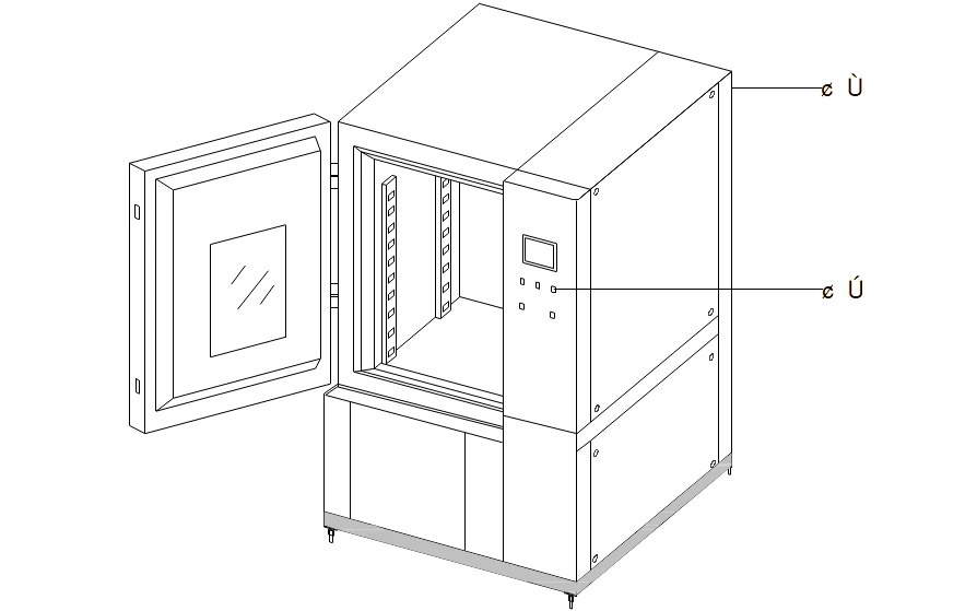
Figure 1
1. Total power source non- melt silk switch (NFB)
2. Power switch (POWER)
3. This machine attaches the window observation lamp, if wants to examine in the box the situation please open "LIGHT" to observe the light switch, in the box the lamp instantly lightens
4. Please beforehand plans procedure of hypothesis diagram of curves the good desire execution, in order to smoothly carries on work the hypothesis。
5. The related procedure hypothesis and the set point control application method, please refer to controller operation showing。
6. If has the breakdown situation occurrence, this machine screen instantly demonstrated the breakdown reason, the buzzer can make a sound, after treats the breakdown condition removes, please do press on the screen "RESET" the key (regression switch), then restarts the testing machine again.