
Get Price
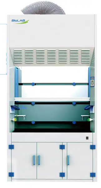
Ducted Fume hood BFSD-403
- 1. It is safer to use anti-corrosive water tap.
- 2. Microprocessor control system, LED display.
- 3. With memory function in case of power-failure.
- 4. Made of porcelain white PP, resistant to acid, alkali and anti-corrosion.
- 5. Front window which is made of 5mm thick transparent toughened glass maximize light and visibility inside the fume hood, providing a bright and open working environment.
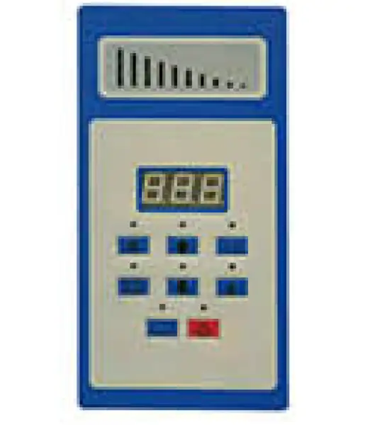
- LED Display
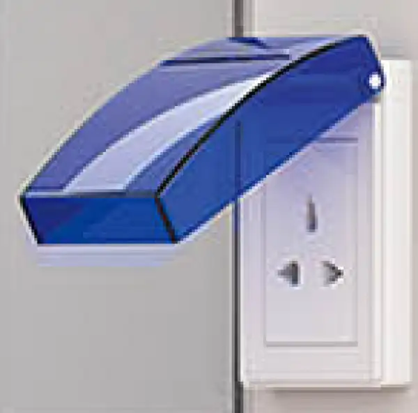
- Waterproof Socket
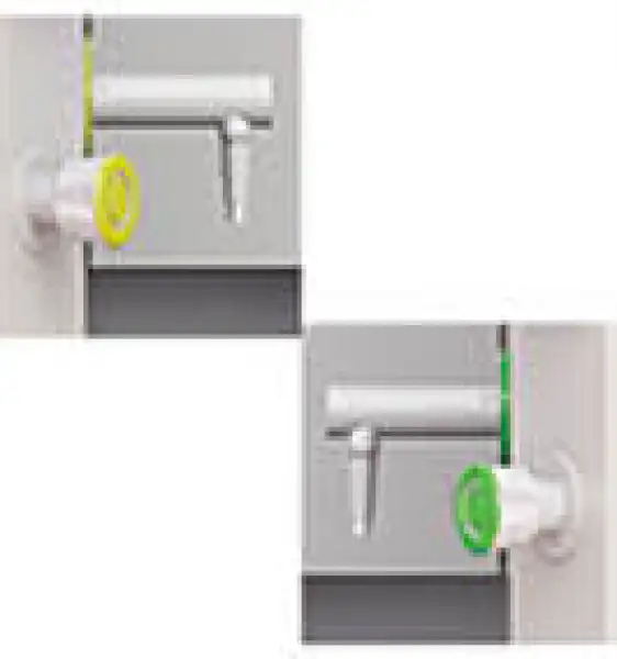
- Water&Gas Remote Control
- Up to 3-Year Product Warranty
- US & EU Compliance Standards
- Door-to-Door Shipping
Technical Specifications
Detailed operating and construction parameters for this model.
| Model | BFSD-403 |
| External Size (W*D*H) | 1547*800*2450mm |
| Internal Size (W*D*H) | 1287*560*700mm |
| 'Work Surface Height | 820mm |
| Max Opening | 740mm |
| Air Velocity | 0.3~0.8m/s |
| Noise | ≤68dB |
| Exhaust Duct | 4.3 meters, φ250mm |
| LED Lamp | 22w*2 |
| Blower | Built-in PP centrifugal blower (2 blowers for FH1800(P) only); Speed adjustable |
| Front Window | Resistant to acid and alkali, Manual, 5Smm toughened glass, height adjustable |
| Power Supply | AC220V±10%, 50/60Hz; 110V±10%, 60Hz |
| Consumption | 500W |
| Material Main Body | Made of Porcelain white PP, thickness 8mm, resistant to strong acid, alkali and anti-corrosion |
| Material Work Table | Chenmical resistant phenolic resin |
| Standard Accessory | LED light;Work table:Chemical resistant phenolic resin; 4.3 meters PVC duct ( 2 Pcs of 4.3 meters PVC duct for FH1800(P) only ), Diameter: 250mm;Pipe strap*2(4 Pcs for FH1800(P) only); RVV power cord (3*1.0mm?*3000mm); Base cabinet; Waterproof socket*2; Tail insert;Water tap(PP); Gas tap(PP); Water Sink;PP centrifugal blower*1(2 for FH1800(P) |
| Gross weight Main Body | 180kg |
| Gross weight Base Cabinet | 114kg or 102kg(Splicable) |
| Package Size (W*D*H) Main Body | 1688*938*1612mm |
| Package Size (W*D*H) Base Cabinet | 1688*888*1000mm or 1700*1000*450mm(Splicable) |
Product Features
Key design, performance, usability, and safety advantages.
1. It is safer to use anti-corrosive water tap.
2. Microprocessor control system, LED display.
3. With memory function in case of power-failure.
4. Made of porcelain white PP, resistant to acid, alkali and anti-corrosion.
5. Front window which is made of 5mm thick transparent toughened glass maximize light and visibility inside the fume hood, providing a bright and open working environment.
LED Display
Waterproof Socket
Water&Gas Remote Control
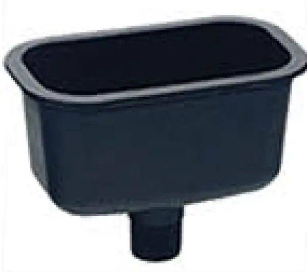
PP Sink, resistant to acid, alkali and anti-corrosion
Operating Manual View instructions, operating procedures, safety information, and maintenance guidance.
1. Unpacking, Installation and Debugging
1.1. Unpacking of Main Body
1.2. Unpacking of Base Cabinet
1.3. Accessories Checking
1.4. Installation Conditions and Operating Environment
1.5. Installation
1.6. Inspection after Installation
2. User Instructions
2.1 Functions
2.2. Product Structure
2.3. Control Panel
2.4. Regular Maintenance
2.5 Wiring Diagram
3. Trouble Shooting and Labels
3.1 Common Failures and Solutions
3.2 Label Description
4. Warranty
1. Unpacking, Installation and Debugging
Please firstly check whether the packing box is in good condition. If the packing box is damaged, please take photos and contact the freight carrier. Biolab and its dealers are not responsible for shipping damages.
1.1. Unpacking of Main Body
Choose a proper unpacking method according to the actual situation.
1.1.1. For wooden box
a) Method 1 Necessary tools for unpacking: Electric drill with hexagon dead M8
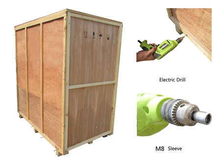
Figure 1
b) Method 2 Use M8 wrench to unpack
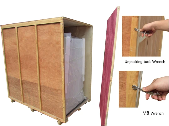
Figure 2
The following diagram demonstrates quick unpacking procedures (Figure 3). Remove the screws shown in the diagram below, then move the wooden pieces to right and left.
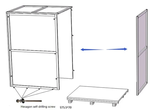
Figure 3
1.2. Unpacking of Base Cabinet
Choose a proper unpacking method according to the actual situation.
Please refer to the main body unpacking method (of the carton box) in the previous pages, use a scissor to cut the packing tape, take off the package cover and move up the box body.

Figure 4
1.3. Accessories Checking
Accessories are placed inside the working area and base cabinet. Please refer to 1.5.6. to take out all accessories and check the completeness referring to this packing list.
Packing list (BFSD 400 series).
Main body box:
No. | Items | Quantity | Remarks |
1 | Upper cabinet | 1 | |
2 | Lower cabinet | 1 | |
3 | Certificate | 1 | |
4 | Warranty card | 1 | |
5 | Power cord | 1 | |
6 | Testing report | 1 | |
7 | Exhaust pipe (with two clamps) | 1 | BFSD-404 has two exhaust pipes (4 with clamps) |
8 | PP centrifugal fan | 1 | BFSD-404 is two |
9 | PP small sink (with drain hose) | 1 | Optional |
10 | Faucet | 1 | Optional |
11 | Faucet control valve | 1 | Optional |
12 | Air faucet | 1 | Optional |
13 | Air faucet control valve | 1 | Optional |
14 | Countertop | 1 | |
15 | Stainless steel bolt | 2 |
Table 1
1.4. Installation Conditions and Operating Environment
1.4.1. Location requirements
The installation position of the fume hood should avoid facing the road and places where people pass frequently, avoid blocking windows and places with unfavorable ventilation and lighting, avoid blocking entrances and exits that affect the switch of the door, and avoid facing and placing them on corner walls.
1.4.2. Environment requirements
a) Only applicable to indoor operation
b) Ambient temperature: 15°C~35°C
c) Relative humidity: ≤75%
d) Atmospheric pressure range: 70 kPa~106 kPa
e) Power supply: the same as the rated voltage and rated frequency of the cabinet, see 2.1.4 technical parameters and performance indicators table;
f) The power supply needs to be reliably grounded; (judgment method: use a multimeter to test the live wire-to-ground voltage of the power supply, which should be the grid voltage, and the neutral wire to ground should be 0, otherwise the power supply grounding is not good).
1.5. Installation
1.5.1. Remove all the package materials
1.5.2. Check the surface of the base cabinet and the main body to make sure there is no scratch, deformation or foreign bodies
1.5.3. Carefully check the attachments and materials against the packing list in the instruction manual;
1.5.4. Move the entire equipment to a site that is as close as possible to the final location and is convenient for installation;
1.5.5. Check whether the ambient voltage frequency is consistent with the voltage frequency displayed on the label, and then power on.
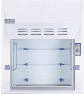
Figure 5
1.5.6. Connect base cabinet with main body
Put the bottom cabinet in a suitable installation position, then put the fume hood cabinet on top of the bottom cabinet, adjust the upper cabinet to be flush with the back and both sides of the bottom cabinet, and fix it with bolts, and the fixing points are behind the two sides of the cabinet.
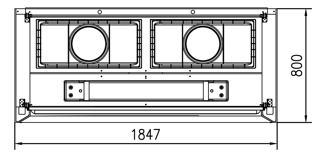
Figure 6
Put the pipe clip on the outer pipe first, then put the outer pipe on the air outlet of the cabinet, and fasten the pipe clip with a flat screwdriver; BFSD-404 has two air outlets, and the main pipe needs to reserve two air inlets for the installation of the exhaust pipe of the fume hood; BFSD-401, BFSD-402, and BFSD-403 all have one air outlet;
(4) Put on the countertop, install the sink on the countertop, and then connect the drain pipe of the sink in the bottom cabinet to the drain outside the cabinet;
1.6. Inspection after Installation
Refer to this table and follow the instruction in 2.3.2, check the following items after powering on the Fume Hood.
Checking Items | Normal working status |
Power status | Equipment could be powered on/switched off when press the power button |
Fan | Runs normally after pressing the Fan button; speed could be adjusted by pressing the adjusting button |
Fluorescent lamp | Lamp lights up after pressing button |
Socket | Use multimeter to test voltage output after pressing the socket button |
Table 2
 NOTE: Please contact Biolab technical department or agent for inspection or trouble shooting when problems could not be solved.
2. User Instructions
2.1 Functions
2.1.1. Product concept
In the chemical laboratory, various harmful and odorous gases, odors, moisture, and corrosive substances will be produced during the experimental operation. In order to protect the safety of users and prevent the pollutants in the experiment from spreading to the laboratory, a fume hood should be used near the pollution source.
2.1.2 Operating principle/air flow pattern
. 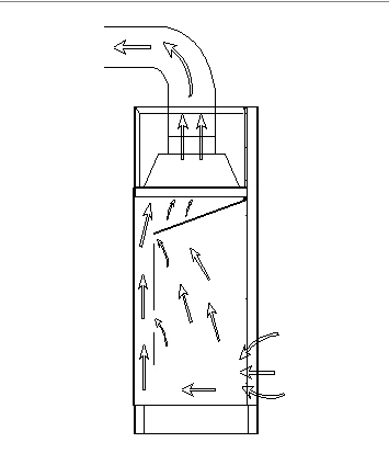
Figure 7
2.1.3. Protected object
Safety is the biggest mission pursued by fume hoods. The use of fume hoods in laboratories is to ensure the safety of users and prevent pollution to the surrounding environment.
2.1.4 Technical parameters
Model Parameter | BFSD-401 | BFSD-402 | BFSD-403 | BFSD-404 |
Rated Voltage AC | 220V±10% 110V±10% | |||
Rated Frequency | 50 Hz 60Hz | |||
External Dimension (W*D*H) | 1047*800*2450 mm | 1247*800*2450 mm | 1547*800*2450 mm | 1847*800*2450mm |
Working Zone Dimension (W*D*H) | 787*560*700mm | 987*560*700 mm | 1287*560*700 mm | 1587*560*700 mm |
Power Supply Consumption | 400 W | 400 W | 500 W | 700 W |
Inflow Velocity | 0.3~0.8m/s | |||
LED fluorescent light power | 24W | 24W | 30W | 36W |
Noise | ≤70dB(A) | |||
Table 3
NOTE: a) Power supply consumption includes the consumption loaded at working zone, which should not exceed 500W.
b) Biolab reserves the right to make changes in future product design, without reservation and without notification to its users.
2.1.5. Performance index
a) Vibration amplitude
The net vibration amplitude, at a range of frequency from 10 Hz to 10 KHz, would not exceed 5 μm (rms)
b) Electrical performance
Dielectric Withstand Test: the Fume Hood would not breakdown in 5s when the voltage increases by 1390V (AC) within 5s
c) Ground resistance ≤0.1Ω
2.2. Product Structure
2.2.1. Structural composition of Fume Hood
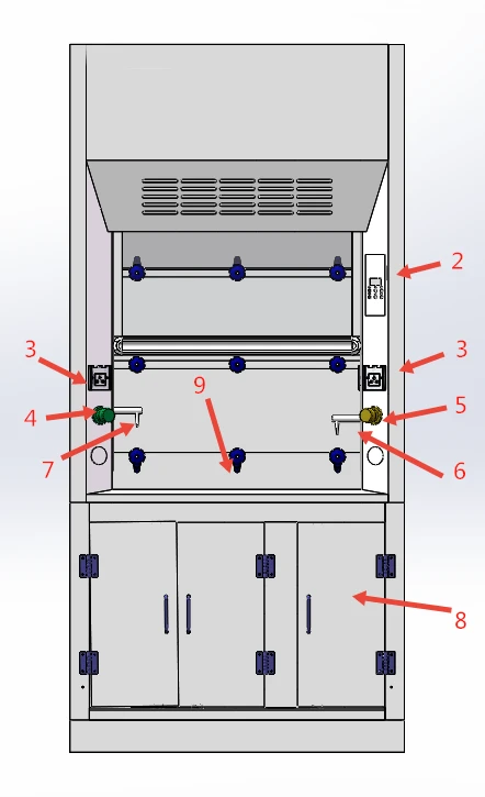
Figure 8
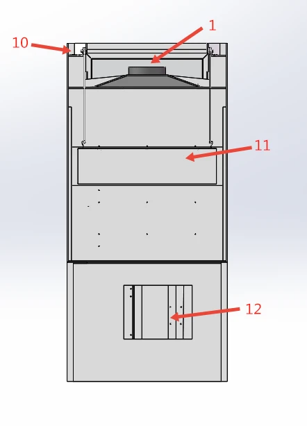
Figure 9
1. fan and the wind barrels 2. control panel 3. Socket 4. Water valve 5.Gas valve 6. Gas faucet 7. fuller faucet. 8. Base cabinet door 9.Table panel 10.Power Supply 11.Clump weight 12.Access wind
Note:BFSD-404 is a double fan.
2.2.2. Structure introduction
Lighting source
LED fluorescent lamps are used for lighting to ensure that the average illuminance in the operating area meets the standard requirements.
Control panel
The operation panel of this equipment has lighting, fan, fan speed control, socket, power touch key and windshield display unit, and various function work display lights. (See below)
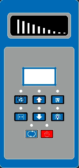
Figure 10
2.3. Control Panel
2.3.1. Soft touch buttons
The key to human-computer interaction is that the main operations of the device can be performed with the touch of a button. Through the function of the buttons, the device can fully realize the most basic functions;
 Power button, the main switch of the Fume Hood
 Fan key: , is the control key of the working state of the fan (Figure 10). Each time it is pressed, the working state and corresponding indicating state change once.
 Fan speed control key: , is the control key of the fan speed (Figure 10). Each time you press it, the working status and the corresponding indication status on the windshield display unit will change once, from F1 gear to F9 gear to adjust 9 gears in turn, when in F9 gear, press the fan speed adjustment button again, then return to F1 gear.
The current value is saved every time the fan gear is adjusted, that is, every time the fan is turned on, it is the working gear when the fan was turned off last time.
 Lighting key: , is the control key of the light (Figure 10). Each time you press it, the state of the lighting tube and the indication state of the corresponding indicator light change once, that is, from on to off, or from off to on;
 Socket key: , is the control key for the power-on and power-off working state of the socket. Every time you press it, the on-off state and the corresponding indication state will change once;
Socket
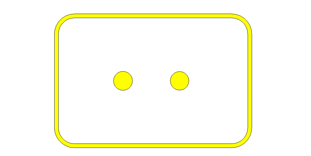
There are sockets on the left and right sides outside the operating area, which can supply power to the equipment in the operating area.
 The power of the equipment used on the socket does not exceed 500W.
Structure
a) PP board for the shell of the fume hood;
b) The operating area of the fume hood is made of PP board, which has high acid and alkali resistance; the countertop is made of solid psychological board, which can be disassembled for easy cleaning.
c) The window of the fume hood is made of 5mm thick tempered glass.
d) The control panel adopts light-touch switches, which makes the machine beautiful in appearance and easy to operate.
e) The electric control system has the functions of anti-overload, anti-electric shock, etc., with stable performance and long service life.
f) The socket adopts special safety products for laboratories, and the material is PC material, which is fire-resistant and flame-retardant.
2.4 Points that should be paid attention to during normal operation and normal operation and use process
2.3.1 Things to pay attention to during operation
Precautions
1. The fume hood is an important laboratory safety equipment. In order to ensure safe and normal use, please read this instruction manual and precautions carefully, and participate in appropriate laboratory safety and skill training;
2. Please read this manual before use.
3. Please keep this manual for future reference.
4. The company will not be responsible for any damage caused by improper use or self-changing product structure.
5. The equipment should not be placed near doors/windows or corridors where people flow frequently.
6. The power socket has good grounding.
7. Please turn off the power and unplug the plug when replacing the lighting lamp.
8. The packaged cabinet should be stored in a well-ventilated environment with no corrosive gas and no relative humidity of more than 75%.
9. The perspective window of the fume hood is made of explosion-proof tempered glass. In order to keep the window clean, it should be wiped with a damp soft cloth and kept away from hydrofluoric acid;
10. Lining accessories such as the deflector of the fume hood should be cleaned regularly according to the usage;
11. The air ducts and fans of the fume hood should be regularly cleaned and maintained by special personnel;
12. Do not place any equipment within 150mm from the glass window. Large-scale experimental equipment must have sufficient space and should not affect the flow of air.
13. During the use of the equipment, do not put soft and delicate items (such as soft paper towels) on the table, so as not to be sucked into the negative pressure air duct and fan by the suction port and affect the operation of the equipment;
14. The product shape and color of the company's pictures are subject to the actual product, and the product model is subject to change without prior notice.
15. The temperature of the contact plate in the operation area cannot be higher than 100°C.
Solemnly declare: The company will not be responsible for the risks caused by the operation not in accordance with the regulations!
2.3.2 Normal operation process
a. Turn on the power, the screen lights up and displays three horizontal bars 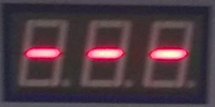 .
.
b. Press the power button on the control panel, and the screen will display the working time of the fan (that is, the working time of the filter, the displayed value multiplied by 10 is the actual time, in hours), Open the glass door, press the fan button , the screen will display the fan gear at the last working time, the fan indicator light above the fan button will light up, and the experiment operation in the cabinet can be carried out normally after 5 minutes of operation.
c. Press the lighting button , the lighting indicator above the button will light up, press the lighting button again to turn off the lighting (you can choose to turn on or off the lighting according to the environment in the laboratory).
d. After use, turn off the fan and lighting, and place the glass door to the bottom.
e. If the power is cut off during use or the power plug falls off under abnormal circumstances, the device will maintain the last working state when the power is turned on again, that is, the working state before power-off when the power is turned on again , with power-down memory function.
2.4. Regular Maintenance
A detailed daily record of operating time is recommended, as the accumulated using time will directly affect the plan of maintenance.
Maintenance should be performed annually or every 1000 operating hours, and every restart.
NOTE: a) To avoid electric shock, please cut off ALL power before applying maintenance for the equipment!
b) The blower and the exhaust duct should be inspected and maintained regularly.
c) The accumulated operating time is a vital factor of deciding when the maintenance is needed. A comprehensive record of operation is highly recommended to be taken down after each time of operating.
Maintenance methods
a) Weekly and monthly maintenance
i. Clean the external surface and front window (refer to 2.4.1.)
ii. Check the various functions of the Fume Hood
iii. Record down the maintenance result
b) Annual maintenance
i. Check the two lifting belt (sash) of the front window tubular motor, make sure both of them are well connected to the motor with same tightness
ii. Check the fluorescent lamp, replace it if needed
iii. Apply for overall performance test of the cabinet annually to ensure that the safety performance has met the requirements. User is responsible for testing costs
iv. Record down the maintenance result
2.4.1 Surface cleaning
In order to keep the cabinet clean, please clean it regularly (recommended at least once a week). When wiping, please use a soft cloth dipped in soapy water and wring it dry. Please do not spray any chemical reagents on the operation panel or other labels to prevent discoloration of the label film or illegible writing. Clean the outer surface of the cabinet and the glass with a soft cleaner or a special cleaner for glass.
2.4.2 Storage conditions
Fume Hood should be stored in a warehouse with relative humidity no more than 75% and temperature lower than 40°C. The warehouse should have good ventilation performance without acid, alkali or other corrosive gases. Storage period shall not exceed one year. Fume Hood stored for more than one year needs to be unpacked and checked before selling and using. Only the tested and qualified safety cabinet could be sold.
2.5 Wiring Diagram
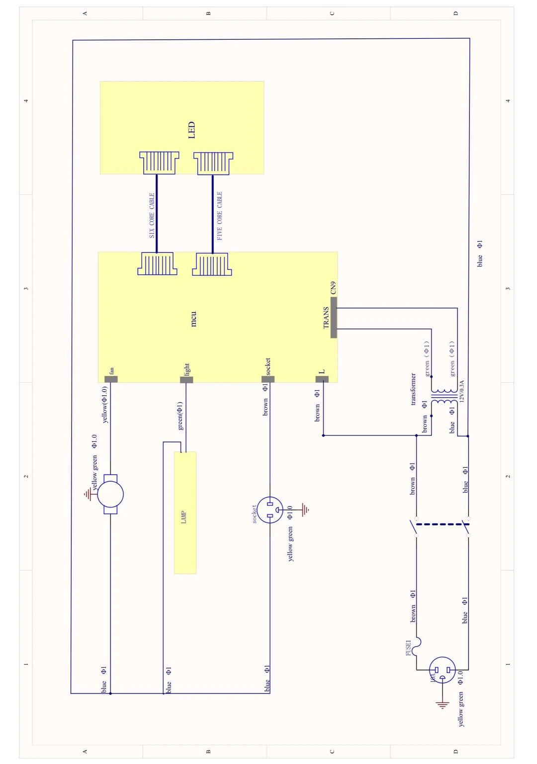
Figure 11
3. Trouble Shooting and Labels
3.1 Common Failures and Solutions
Before diagnosing the fault, please confirm whether the power supply is connected well, whether the power cord is obviously damaged, and whether the fuse is in good condition.
1. Check whether the equipment has implemented reliable grounding measures according to the requirements in the manual to ensure the safety of maintenance and use. Check whether the electrical wiring of the equipment is disconnected, disconnected or short-circuited. If there are similar situations, they should be eliminated in turn;
2. Judgment and solution of common faults
Failures | Checking Part | Suggestion |
Fluorescent lamp fail to work | Fluorescent lamp tube | Replace the fluorescent lamp tube |
Circuit | Check the circuit | |
Control panel | Replace the control panel | |
Button fail to work | Control panel | Make sure the power is well connected and the fuse is in good condition |
Check if the button is broken | ||
Make sure the connecting wire is well connected | ||
Replace the control panel | ||
Fan fail to work | Fan | Replace the fan if it is defective |
Circuit | Check the circuit | |
Control panel | Replace the control panel | |
No electricity in socket | Socket fuse | Check if the socket fuse is broken |
Socket | Check if the socket is broken | |
Circuit | Check the circuit | |
Control panel | Replace the control panel | |
No electricity in equipment | Power supply | Check whether the power supply is well connected |
Power cord | Check whether the power cord is in good condition | |
Fuse | Check if the fuse is damaged | |
Potential transformer | Check whether the transformer works normally | |
Control panel | Replace the control panel | |
Display fail to work | Signal transmission line | Check whether the signal transmission line is well connected |
Display screen | Check whether the screen is in good condition | |
Control panel | Replace the control panel |
Table 4
3.1.1.Simple accessories replacement
a) Replace the fuse
The round safety tube on the top of the right panel of the fume hood cabinet is determined according to the label, which is F10A φ5x20 mm. When it is necessary to replace the FireWire fuse, use a flat-head screwdriver to lift out the fuse holder and replace it, and then press it back.
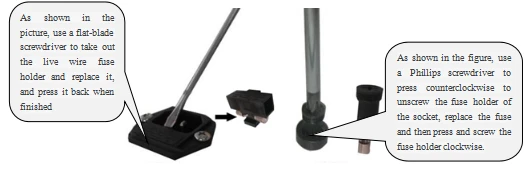
Figure 12
b) Replace fluorescent light
When the lighting lamp of the fume hood is broken and needs to be replaced, press the glass door up button to raise the glass door to the highest height, then disconnect the power supply, remove the power cord of the LED fluorescent lamp, Use a screwdriver to remove the lampshade fixing device, remove the old LED fluorescent tube, replace it with a new one, and then connect the power cord of the LED fluorescent lamp, and the power-on test is correct.
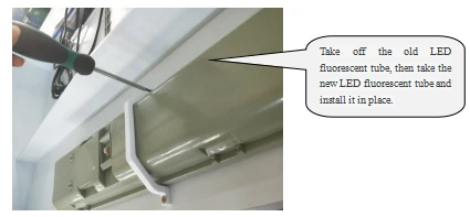
Figure 11
 Note:
Note:
(1) The operation of the above electrical components must be carried out by a qualified electrician under safe conditions (cut off the power supply). All other parts are not allowed to be disassembled, otherwise the consequences shall be borne by the user;
(2) When the equipment does not have the above failures and the operator cannot eliminate them immediately, please notify our company's maintenance department immediately. For your safety, please do not repair the equipment by yourself;
(3) The maintenance work of this equipment can only be undertaken by trained and approved technical personnel;
(4) If you need to order parts, you can find our technical service department, please indicate the model and serial number of the fume hood you purchased.
3.2 Label Description
3.2.1 Fuse label
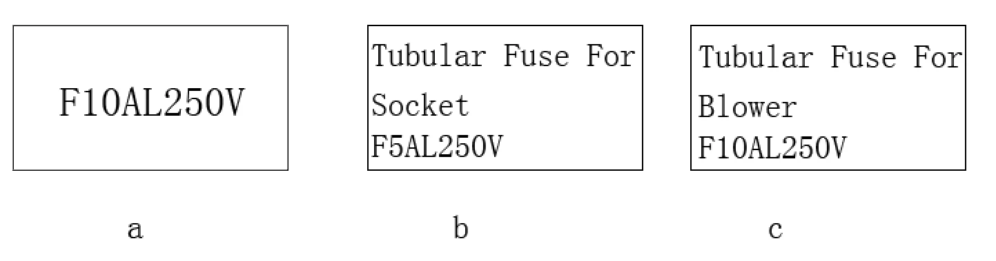
Figure 13
Note: The 10A fuse indicator label is located under the live wire fuse
3.2.2. Ground label

Figure 14
4. Warranty
4.1. Warranty is 12 months from EX-factory date (excluding consumable accessories, Fluorescent lamp, fuse
4.2. Biolab would not be liable for any repair of damage caused by improper operation
4.3. If the warranty has been expired, Biolab would still responsible for repair with relative charges
4.4. Life time of fume hood is 8 years from production date on the label
4.5. Biolab would provide equipment drawings and necessary technical data for maintenance companies or personnel trained by Biolab engineers.