
Get Price
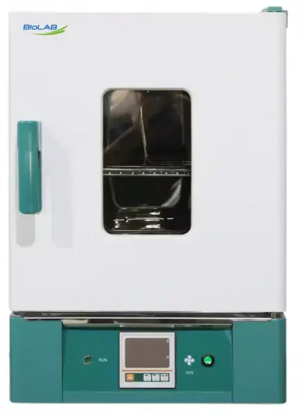
Drying Oven BER-505
- 1. Horizontal air circularly by double Air ducts, high efficiency and high uniformity.
- 2. PID controller, with over-temperature protection function.
- 3. With fan switch,LED digital display,high temperature blast motor.
- 5. New anti-hot handle.
- Up to 3-Year Product Warranty
- US & EU Compliance Standards
- Door-to-Door Shipping
Technical Specifications
Detailed operating and construction parameters for this model.
| Model | BER-505 |
| Cycle Mode | Forced convection |
| Function | |
| --Temp. Range | RT+10-300°C |
| --Temp. Resolution Ratio | 0.1°C |
| --Temp. Motion | ±1°C |
| --Temp. Uniformity | ±2.5% |
| Structure | |
| --Inner Chamber | Mirror Stainless Steel |
| --Quter Shell | Cold rolling steel electrostatic spraying exterior |
| --Insulation Layer | High quality rock wool board(with CE) |
| --Heater | Stainless steel heater |
| --Power Rating | 2.3kW |
| --Exhaust Hole | Φ35mm top(with function of test hole) |
| Controller | |
| --Temp. Control Mode | Two temperature section PID intelligent |
| --Temp. Setting Mode | Touch button setting |
| --Temp. Display Mode | LED Digital display |
| --Timer | 0-9999min(with timing wait function) |
| --Operation Function | Fixed temperature operation, timing function, auto stop. |
| --Additional Function | Sensor deviation correction, temperature overshoot self-tuning, internal parameter locking, power-off parameter memory |
| --Sensor | PT100 |
| --Safety Device | Over temperature sound-light alarm; |
| Specification | |
| --Inner Chamber size(W*L*H)(mm) | 500*450*550 |
| --Exterior Size (W*L*H)(mm) | 636*680*915 |
| --Packing Size (W*L*H)(mm) | 710*730*1100 |
| --Volume | 125L |
| --Max. Shelf Number | 11 |
| --Load Per rack | 15kg |
| --Shelf Space | 40mm |
| --Power Rating (50/60HZ) | AC220V/10.5A |
| --NW/GW (kg) | 60/66 |
| Accessory | |
| --Shelf | 2 |
| --Shelf Frame | 4 |
| Optional accessories | Spare shelf |
Product Features
Key design, performance, usability, and safety advantages.
Applications Explore common laboratory, research, industrial, and process applications.
Easy to operate efficient dry heat sterilizer.
Operating Manual View instructions, operating procedures, safety information, and maintenance guidance.
1. Safety warning before use
2. Main features of product
3. Technical Specification
4. Instrument operation and display instructions
5. Instrument wiring diagram
6. General faults and troubleshooting methods
1. Safety warning before use
 Must prohibit items
1. Do not store volatile, flammable, or explosive materials in this device, as it may cause explosions or fires.
2.Do not place this device in a place that is exposed to rain, moisture, or may splash water, otherwise it may cause accidents such as leakage, short circuit, or electric shock.
 professional technicians are not allowed to disassemble, repair, or modify equipment, otherwise improper operation may cause fire or electric shock accidents to personnel。
Must comply with items
1.This device should be installed on a solid ground. If the ground is not solid enough or the installation location is not suitable, personnel may be injured due to equipment overturning.
2. Please use the dedicated power supply indicated on the nameplate of this device, and the power socket must be grounded. This device must be reliably grounded to prevent accidental electrical leakage that may cause electric shock or fire.
3. Before carrying out any repairs or maintenance on this equipment, be sure to disconnect the power supply to prevent electric shock or personal injury.
4. When repairing or maintaining equipment, it is necessary to wear gloves to prevent personal injury caused by touching edges or sharp corners.
5.If any abnormalities are found in the operation of the device, immediately unplug the power plug and stop the device from running. Operating under abnormal conditions may cause electric shock or fire。
2. Main features of product
1. Unique vertical dual duct circulating horizontal air supply, with uniform temperature distribution in the studio.
2. Digital tube display microcomputer intelligent PID temperature controller.
3. Standard fan switch, high brightness LED instrument operation indicator light, and high-temperature resistant blower motor.
4. New anti scald handle.
1. The temperature controller's color LCD screen displays the set value, measured value, and timing simultaneously on the screen.
A 2.4 speed 3-speed speed adjustable fan can adjust the required air volume according to different sterilization requirements of users, thereby sterilizing various types of samples.
3. Independent over temperature protection system: When the temperature in the studio exceeds the alarm value set by the instrument, cut off the main heating circuit to improve safety.
4. Independent temperature limiter: High precision digital display independent temperature limiter, set to limit the temperature of the studio, providing dual safety protection for the product.
3. Technical Specification
Model | BER-501 | BER-502 | BER-503 | BER-504 | BER-505 | BER-506 | |
Cycle Mode | Forced convection | ||||||
Function | Temp. range | RT+10-300°C | |||||
Temp. Resolution Ratio | 0.1°C | ||||||
Temp. Motion | ±1°C | ||||||
Temp. Uniformity | ±2.5% | ||||||
Structure | Inner Chamber | Mirror Stainless Steel | |||||
Outer Shell | Cold rolling steel electrostatic spraying exterior | ||||||
Insulation layer | High quality rock wool board (with CE) | ||||||
Heater | stainless steel heater | ||||||
Power rating | 0.8kW | 1.2kW | 1.6kW | 2.0kW | 2.3kW | 3.0kW | |
Exhaust hole | φ35mm top(with function of test hole) | ||||||
Controller | Temp. control mode | Two temperature section PID intelligent | |||||
Temp. setting mode | Touch button setting | ||||||
Temp. display mode | LED Digital Display | ||||||
Timer | 0-9999min(with timing wait function) | ||||||
Operation function | Fixed temperature operation, fixed timing function, auto stop. | ||||||
Additional Function | Sensor deviation correction, temperature overshoot self-tuning, internal parameter locking, power-off parameter memory | ||||||
Sensor | Pt100 | ||||||
Safety Device | Over temperature sound-light alarm; | ||||||
Specification | Inner Chamber size(W*L*H) (mm) | 310*310 *310 | 350*350 *350 | 400*360 *450 | 450*420 *450 | 500*450 *550 | 600*500 *750 |
Exterior size (W*L*H)(mm) | 460*510 *695 | 500*550 *735 | 550*550 *840 | 590*610 *830 | 636*680 *915 | 735*835 *1115 | |
Packing size (W*L*H)(mm) | 540*575 *855 | 580*615 *895 | 635*625 *995 | 680*685 *1000 | 710*730 *1100 | 857*885 *1287 | |
Volume | 30L | 45L | 65L | 85L | 125L | 230L | |
Shelf number | 5 | 6 | 8 | 8 | 11 | 17 | |
Load per rack | 15kg | ||||||
Shelf space | 40mm | ||||||
Current rating (50/60HZ) | AC220V/ 3.6A | AC220V/ 5.5A | AC220V/ 7.2A | AC220V/ 9.0A | AC220V/ 10.5A | AC220V/ 13.6A | |
NW/GW (kg) | 33/37 | 37/43 | 44/49 | 50/56 | 60/66 | 94/120 | |
Accessory | Shelf | 2 | |||||
Shelf frame | 4 | ||||||
optional accessories | Spare shelf, RS485 interface, printer, program controller, U-disk storage; 3.5-inch color touch screen temperature controller | ||||||
Table 1
4. Instrument operation and display instructions
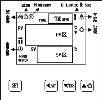
Figure 1
![Figure 2, 1.Instrument operation and usage, Key Definition, 1. [SET]: Set button. When the main interface displays the](https://biolabscientific.com/content/manual/20260714002/Figure-2-i5-Biolab.webp "Figure 2")
Figure 2
1.Instrument operation and usage
Key Definition
1. [SET]: Set button. When the main interface displays the status, click this button to enter the temperature and time target value setting state. Long press this button for 3 seconds to enter the internal parameter setting state.
2. { ![Figure 2, 1.Instrument operation and usage, Key Definition, 1. [SET]: Set button. When the main interface displays the](https://biolabscientific.com/content/manual/20260714002/Figure-2-i6-Biolab.webp "Figure 2") }: Shift/self-tuning key. Clicking this key in the set state can cause the set value to shift and flash for modification.
}: Shift/self-tuning key. Clicking this key in the set state can cause the set value to shift and flash for modification.
In the main interface display state, long press this button for 6 seconds to enter the temperature self-tuning selection state.
3. [ ![Figure 2, 1.Instrument operation and usage, Key Definition, 1. [SET]: Set button. When the main interface displays the](https://biolabscientific.com/content/manual/20260714002/Figure-2-i7-Biolab.webp "Figure 2")
![Figure 2, 1.Instrument operation and usage, Key Definition, 1. [SET]: Set button. When the main interface displays the](https://biolabscientific.com/content/manual/20260714002/Figure-2-i8-Biolab.webp "Figure 2") ]: The decrease/rerun button can be used to decrease the set value by clicking or long pressing it in the set state.
]: The decrease/rerun button can be used to decrease the set value by clicking or long pressing it in the set state.
Press and hold this button for 3 seconds in the main interface and at the end of the run state to restart the operation.
4. [ ![Figure 2, 1.Instrument operation and usage, Key Definition, 1. [SET]: Set button. When the main interface displays the](https://biolabscientific.com/content/manual/20260714002/Figure-2-i9-Biolab.webp "Figure 2") ]: Add/lock screen button, click or long press this button in the set state to gradually increase the set value.
]: Add/lock screen button, click or long press this button in the set state to gradually increase the set value.
If the lock screen function is selected, in the main interface display state, click this button to lock or unlock the screen.
Definition of digital tube display type instrument indicator lights:
1. [AT/F] indicator light: This light comes on when the temperature unit is Fahrenheit, flashes during the temperature self-tuning process, and goes off in other states.
2. [TIM] indicator light: It lights up when there is a timing setting, flashes during the reservation timing process, and goes off when there is no timing function.
3. [OUT] indicator light: When there is heating output, this light will turn on, and vice versa, it will turn off.
4. [LOC] indicator light: lights up in lock screen mode, otherwise goes off.
5. [SIN] indicator light: Invalid reservation.
6. [ALM] indicator light: When there is a temperature deviation alarm or abnormal temperature measurement, this light will turn on. When there is a temperature deviation alarm, this light will flash. Under normal conditions, this light will turn off.
Definition of LCD instrument indicator lights:
1. [Main interface] Indicator light: This light will light up in normal working state (not set state), and turn off in reverse.
2. [Lock] indicator light: It lights up in the lock screen state, and goes off in the opposite direction.
3. [AT] indicator light: During the temperature self-tuning process, this light flashes, otherwise it goes out.
4. [Alarm] Indicator light: When there is a temperature deviation alarm or abnormal temperature measurement, this light will turn on. When there is a temperature deviation alarm, this light will flash. Under normal conditions, this light will turn off.
5. [Heating] Indicator light: When there is heating output, this light will turn on, and vice versa, it will turn off.
6. [A] Indicator light: This light flashes during the reservation timing process, and goes off if not.
7. [RUN/STOP] indicator light: STOP will only light up after the timer ends, and RUN will light up in other states.
8. [↑/→/↓] Indicator lights: They flash respectively during heating, constant temperature, and cooling.
2. Operation and usage methods
In the main interface display state, click the [Set] button to enter the temperature setting state. The PV area displays the prompt SP, and the SV area displays the temperature setting value. The modification method is the same as above; Click the [Set] button again to enter the time setting state. The PV area displays the prompt ST, and the TIME area displays the time setting value; Click the [Settings] button again to exit this setting state, and the set values will be automatically saved.
Explanation: LCD type, "symbol" represents "time unit";
Digital type, with the symbol "TIME display area decimal point".
3. Reference and setting of internal temperature parameters
In the main interface display state, long press and hold the [Set] button for 3 seconds. The password prompt Lc will be displayed in the PV area, and the password value will be displayed in the SV area. Use [Increase], [Reduce], and [Shift] to modify the desired password value. Then click the [Set] button. If the password value is incorrect, the instrument will automatically return to the main interface display state. If the password value is correct, enter the internal parameter setting state, and click the [Set] button to modify each parameter in sequence. During this process, long press the [Set] button for 3 seconds to exit this state, and the parameter values will be automatically saved. Please refer to the table below for details:
Explanation: In the parameter table, the temperature setting value is abbreviated as SP, and the temperature measurement value is abbreviated as PV.
Indicator | Parameter Name | Indicator | (Scope) Factory value |
Lc | password | When Lc=3, parameter values can be viewed and modified. | 0 |
ALH | upper deviation over temperature alarm. | When PV>SP+ALH, there is an upper deviation over temperature alarm. | (0~100.0°C) 20.0 |
ALL | Lower deviation over temperature alarm | When PV < SP-ALL, there is a lower deviation over temperature alarm. Explanation: When ALL=0, the lower deviation alarm is invalid. | (0~100.0°C) 0 |
Pb | Correction of measurement temperature deviation | Used to correct errors generated during temperature measurement. Pb=actual temperature value - PV | (-50.0~50.0°C) 0 |
PL | Correction of Measurement temperature slope deviation | Usually used to correct errors generated during high-temperature measurements. PL=1000 * (actual temperature value - PV) ÷ PV | (-999~999) 0 |
ndT | Timing method | 0: No timing; 1: Constant temperature timing; 2: Run timing | (0~2) 1 |
Tdn | Timing direction | 0: Positive timing; 1: Countdown | (0~1) 0 |
Hn | Timing unit | 0: minutes; 1: Hour | (0~1) 0 |
SPd | Constant temperature deviation | When SP SPd ≤ PV ≤ SP+SPd, enter a constant temperature state | (0.1~50.0°C) 0.5 |
EST | End Timing Prompt Time | When the timing ends, the buzzer indicates the time. Note: when the EST = 9999, said a permanent reminder | (0~9999) 60 |
EH | End Timing Constant Temperature Controller | 0: Turn off the heating output after timing; 1: Keep constant temperature controlling after timing | (0~1) 0 |
LF | Lock Screen Function | 0: Lockless screen function; 1: Lock screen function, unlock without password. 2: Lock screen function, need password to unlock. | (0~2) 0 |
LdT | Lock Screen Delay | In the main screen state, if no key is pressed in the delay LDT time, the controller will automatically lock the screen. Description: LDT = 600, the delay screen locking function is invalid | (10~600s) 30 |
PAd | Unlock Password | The password must be entered to unlock it. | (0~9999) 1 |
Add | Mail Address | Local Address Description: PC-E9000 has no communication function. | (1~32) 1 |
Table 2 (Parameter Table)
Indicator | Parameter Name | Parameter Function Description | (Scope) Factory value |
Lc | password | When Lc=567, parameter values can be viewed and modified. | 0 |
rST | factory reset | 0: Cancel; 1: Confirm. | (0~1) 0 |
Table 3 (Parameter Table)
5. Instrument wiring diagram
 :Represents the charged output, should be directly connected to the load.
"  ":Represents the switch output without charge.
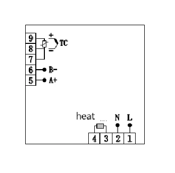
Figure 3
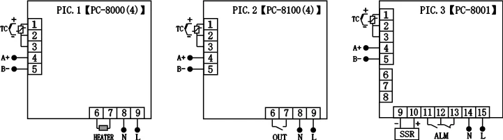
Figure 4
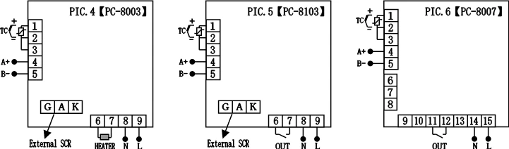
Figure 5
6. General faults and troubleshooting methods
Fault phenomenon | Fault inference | Fault handling methods |
No display on startup The measured temperature is higher than the set temperature or the instrument enters a high temperature alarm state After turning on, the temperature does not display and does not rise Fault phenomenon | Power supply not connected | Check for voltage in the power socket |
The power plug is not properly plugged in | Check if the contact between the power plug and the socket is reliable | |
The power switch is not turned on | Turn on the power switch on the right side of the instrument | |
The fuse on the box is damaged | Replace the power fuse with the same specification | |
No display on startup The measured temperature is higher than the set temperature or the instrument enters a high temperature alarm state | The box door is not tightly closed | Close the box door tightly |
The instrument has not yet entered a constant temperature state | Wait for a moment before making an observation | |
After turning on, the temperature does not display and does not rise | The power cord is not properly plugged in | Insert the power cord properly |
Sensor malfunction | Notify the factory for repair | |
The heater is broken | Notify the factory for repair |
Table 4