
Get Price
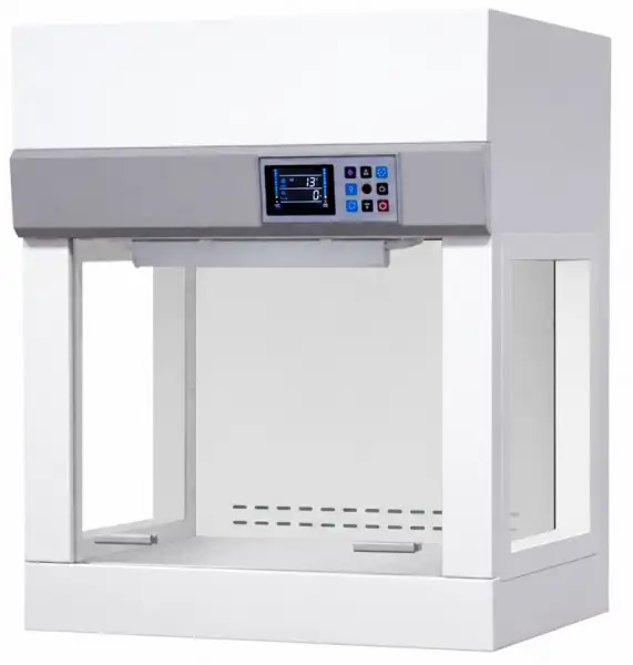
Desktop Laminar Airflow BJU-2301
Mini Laminar Flow Cabinet provides sample protection as purified air travels across the working zone of the cabinet in a vertical, unidirectional stream and leaves the main work chamber across the entire open front of the cabinet.
- Up to 3-Year Product Warranty
- US & EU Compliance Standards
- Door-to-Door Shipping
Technical Specifications
Detailed operating and construction parameters for this model.
| Model | BJU-2301 |
| Internal Size (W*D*H) | 480*340*370mm |
| External Size (W*D*H) | 580*460*700mm |
| Maximum Opening | 310mm |
| Control System | Microprocessor controller with LCD display, display the operating status of each function |
| Airflow Velocity | 0.2~0.6m/s, Intelligent multi-level adjustable |
| Pre-Filter | 1pcs, Polyester fiber,washable |
| HEPA Filter | 1 pcs, Efficiency: > 99.995% at particle size of 0.3μm |
| Cleanliness Grade | ISO Class 5 (formerly Class 100) |
| Partial Air Circulation | Perforations at the back wall of the work zone which are designed to eliminate air turbulence and the possibility of dead air corners in the work zone. |
| Main Body | Electro-galvanized steel with antimicrobial powder coating |
| Work Surface | 304 Stainless steel |
| Front Window | Manual, 5 mm UV resistant tempered glass |
| UV Lamp | 8Wx1 |
| LED Lamp | 8Wx1 |
| Consumption | 110W |
| Power Supply | AC220V±10%, 50/60HZ; 110V±10%, 60Hz |
| Sound Emission | ≤62dB(A) |
| Colony Count | ≤0.5pcs/vessel (petri dish is φ 90mm) |
| Vibration | ≤3um |
| Work Surface Bearing | 10kg |
| Standard Accessory | 1.LED Lampx1; 2.UV Lampx1; 3.Pre-filterx1; 4.HEPA Filterx1 |
| Net Weight | 36kg |
| Gross Weight | 41kg |
| Shipping Size (WxDxH) | 710x590x850mm |
| Shipping Volume | 0.36m³ |
Operating Manual View instructions, operating procedures, safety information, and maintenance guidance.
1. Description
2. Technical Parameters
3. Working Requirements
4. Panel Instruction
5. Wiring Diagram
6. Installation Conditions and Operating Environment
7. Installation
8. Common failure and solution
1. Description
Vertical Laminar Flow Hood / Cabinet (also called clean bench) provides sample protection as purified air travels across the working zone of the cabinet in a vertical, unidirectional stream and leaves the main work chamber across the entire open front of the cabinet.
Most Vertical Laminar Flow Hoods also have perforations at the back wall of the work zone which are designed to eliminate air turbulence and the possibility of dead air corners in the work zone.
Humanized Features :
Ergonomic Control Panel Location, centered and angled down for an easy reach & viewing.
Brushed stainless steel work surface is for easy cleaning.
The non-direct light source design can effectively relieve the operator's visual fatigue under the condition of ensuring the illumination.
Intuitive and easy-to-use microprocessor controller with LCD display, graphical and digital display of the operating status of each function, such as filter life, UV life etc.
Safety Features :
Front sliding sash interlock with fan and UV lamp.
UV sterilization with UV lamp timing function.
Front sash and side windows are made of UV-resistant tempered glass.
The host and sockets have independent capacitors to prevent current overload.
Convenience Features :
Memory function in case of power-failure.
HEPA filter and UV life indicators facilitate a timely replacement plan.
Two side glass windows installed for easy experiment observation.
Easy-to-change pre-filter installed could extend the HEPA filter's lifetime.
Equipped with a temperature sensor to show the real temperature during operation.
Waterproof sockets provide convenience for small instruments to be used in the operating area.
2. Technical Parameters
Parameter | Specification | |
Model | BJU-2301 | |
External Size (WxDxH) (mm) | 590x460x700 | |
Internal Size (WxDxH) (mm) | 480x340x370 | |
Max Opening | 310 mm | |
Control System | Microprocessor control with LCD display, display the operating status of each function | |
Airflow System | Airflow Velocity | 0.2-0.6 m/s, intelligent multi-level adjustable |
Pre-Filter | 1 pcs, Polyester fiber, washable | |
HEPA Filter | 1 pcs, Efficiency: >99.995% at particle size of 0.3 μm | |
Cleanliness Grade | Class 100 (ISO 14644-1 Class 5) | |
Cabinet Construction | Partial Air Circulation | Perforations at the back wall of the work zone which are designed to eliminate air turbulence and the possibility of dead air corners in the work zone. |
Main Body | Electro-galvanized steel with antimicrobial powder coating | |
Work Surface | 304 Stainless steel | |
Front Window | Manual, 5 mm UV resistant tempered glass | |
Electrical System | UV Lamp | 8Wx1 |
LED Lamp | 8Wx1 | |
Consumption | 110W | |
Power Supply | AC220V±10%, 50/60Hz; 110V±10%, 60Hz | |
Sound Emission | ≤62 dB | |
Colony Count | ≤0.5 pcs/vessel (petri dish is φ 90 mm) | |
Vibration | ≤3 μm | |
Work Surface Bearing | 10 kg | |
Standard Accessory | 1 LED Lampx1; 2 UV Lampx1; 3 Pre-filterx1; 4 HEPA Filterx1 | |
Net Weight | 36 kg | |
Gross Weight | 41 kg | |
Shipping Size (WxDxH) (mm) | 710x590x850 | |
Shipping Volume | 0.36 m³ | |
Table 1
3. Working Requirements
1. Electricity: 220VAC±10% (or 110VAC±10% optional)
2. Power frequency: 50/60Hz;
3. Ambient temperature: - 10~60°C;
4. Relative humidity: < 90%RH (Non-condensing)
4. Panel Instruction
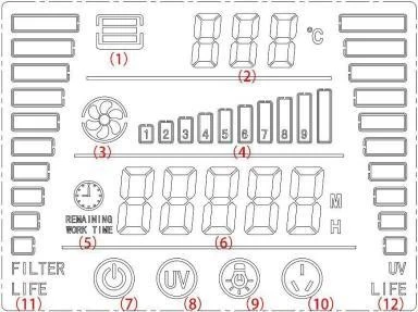
Figure 1
(1) Door Status Icons
When the door is open, the icon goes out in the middle and the outer frame lights up; When the door is closed, this icon is all lit.
(2) Ambient temperature
In the running state, the current ambient temperature measurement value is displayed; When the password is entered, it will be displayed as "PA";
In the parameter setting state, it is displayed as the English abbreviation of the corresponding parameter;
(3) Fan icons
When the fan is running, the icon lights up and turns;
(4) Fan Gear Icon
Displayed according to the fan setting gear;
(5) Time remaining icon
(6) Run time icon
In the running state, the cumulative running time of the fan is displayed; In UV sterilization state, the remaining time of sterilization is displayed; When UV sterilization is completed, it will display as "End";
When the password is entered, it will be displayed;
(7) Power Icon
When the power is off, the icon lights up;
(8) UV Sterilization Icon
When the system is in UV sterilization state, the icon flashes;
(9) Lighting icon
When the lighting is on, the icon lights up;
(10) Socket icon
When the power supply is turned on, the icon lights up;
(11) Filter lifespan scale bar
When the life is 0, it goes out;
When the life is not 0, the corresponding ratio (tenth ratio) is displayed;
(12) Sterilization lamp lifespan scale bar
When the lifespan is 0, it turns off;
Button Definition (two styles exist) :
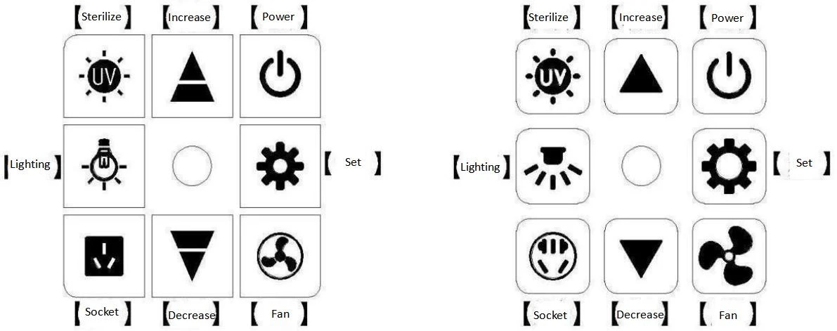
Figure 2
[Power] key: The power switch key, click to turn the power on or off.
[Lighting] key: Lighting on/off key, click to turn on or off the lighting.
[Socket] key: Socket switch key, click to open or close the socket.
[Sterilize] key: Sterilization lamp switch key (when the door is closed, the lighting is closed, the socket is closed, and the fan is closed, press and hold for 3 seconds to turn on UV sterilization).
[Fan] key: Fan switch key (when the fan is off, the fan icon is off, and the fan gear bar is off; when the fan is on, the fan icon is displayed, and the fan gear bar shows the current gear).
[▲] [▼] Increase & Decrease keys(When the fan is off, increase or decrease the set value of the gear; when the fan is on, directly increase or decrease the gear; when the parameter is set or the password is entered, the parameter value or password is increased or decreased).
[Set] key: Click the setting button to enter the password input interface, modify the input password through the increase & decrease buttons, and then click the setting button to enter the corresponding parameter setting interface ; In the parameter setting interface, click the setting button to cycle the settings, and modify the parameters through the increase & decrease buttons. Press and hold the setting button for 3 seconds to exit and save the settings.
Interlock function description :
The fan can only be turned on when the door is open;
When the door is closed, turn off the lighting, turn off the socket, and turn off the fan at the same time to start the sterilization;
Sterilization time setting :
Click the setting button to enter the password input interface, which is displayed as "PA" ; Change the input password to " 1" by the increase & decrease keys, click the setting key to confirm, and it will display as "UT" at this time ; Modify the value to the value specified by the customer through the increase & decrease keys, and click the set key to exit.
5. Wiring Diagram
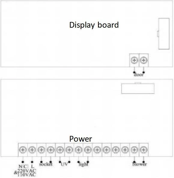
Figure 3
6. Installation Conditions and Operating Environment
Laminar flow cabinet shall be placed in a protection area, workspace can not be right opposite to the door or window, and away from the outlet of air conditioning, prevent from the ventilation system,air conditioning, door,window, and personnel movement caused by the airflow impact on Laminar flow cabinet.
At least 300mm gap must be kept in the side and back side of the Laminar Air Flow for clean operation and for inspection.
Working environment :
1) Only applicable for indoor operation.
2) Ambient temperature:15°C ~35°C.
3) Relative Humidity: ≤75%.
4) Atmospheric pressure range: 70KPa~106KPa.
5) Electrical parameters: Adequate power supply to the laminar flow cabinet. Power supply needs to be grounded;(Judging method: test the live wire and the neutral wire of the socket with multimeter. The voltage between live and ground should equal the voltage of the local electrical grid, and the voltage between neutral and ground should equal 0. Otherwise the power supply is not grounded correctly).
7. Installation
a. Remove all the package materials
b. Check the surface of the base cabinet and the main body to make sure there is no scratch, deformation or foreign bodies.
c. According to the packing list of instructions, count carefully the accessories and materials.
d. Position the base cabinet to the final location where an appropriate power supply is nearby. Move the whole equipment as close as possible to the final installation place.
e. Connect the base stand and main body.
Inspection after Installation :
Check whether the voltage on the nameplate of the equipment is consistent with the actual supplied voltage, power on the equipment, turn on the display switch, and check the following items.
Checking Items | Normal working status |
Power status | Equipment could be powered on/switched off when press the power button |
Fan | Runs normally after pressing the Fan button; speed could be adjusted by pressing the adjusting button |
LED lamp | Lamp lights up after pressing button |
UV Lamp | Lamp lights up after pressing button |
Socket | Use multimeter to test voltage output after pressing the socket button |
Table 2
NOTE: Please contact the technical department or agent for inspection or trouble shooting when problems could not be solved. Methodology of trouble shooting is stated in the After-sale Service Manual.
8. Common failure and solution
Please confirm that the power is well connected, the cord is in good condition (without any damage) and the power lock is unlocked before trouble shooting the following problems.
Faults | Check Parts | Suggestion |
LED light does not light up or abnormal | Lamp holder | Check that the lamp tube and the lamp holder are firmly connected |
Light tube | Replace the lamp | |
Line | Check the line | |
Control panel | Replace the control board | |
UV lamp does not turn on or abnormal | Interlock | Check the LED lamp and the blower is open or not |
Lamp holder | Tube and lamp holder is connected securely | |
Circuit | Check circuit | |
Ballast | Change it | |
UV lamp | Change it | |
Micro Switch | Check if Micro Switch is broken | |
Control panel | Change it | |
Buttons do not work | Control panel | Make sure the power connects well and the fuse is well |
Control panel | Check if the button is broken | |
Control panel | Make sure the connecting wire is connected well | |
Control panel | Change control panel | |
Fan does not turn | Fan | The fan is damaged, replace the fan |
Micro Switch | Determine whether the micro switch is closed | |
Line | Check the line | |
Control panel | Replace the control board | |
The device is not powered | Power supply | Check power supply connects well |
Power wire | Check whether power wire has obvious damage | |
Fuse | Check if the fuse is good | |
Switch | Whether there is a problem with the power switch and terminal wiring is off or loose | |
The display does not light up | Transformer | Check whether the transformer works normally |
Control panel | Change it | |
Connection winding displacement | Check whether the connection cable is in good contact | |
Display screen | Check if the display is good | |
Control panel | Replace the circuit board |
Table 3
NOTE :
(1) The above trouble shooting methods should be done by qualified electricians under safe conditions(cut off power supply). Other components should not be removed.Risk caused by failing to follow those instructions would be responsible by the user.
(2) The trouble shooting and repair of this equipment only could be undertaken by trained and recognized technicians.