Get Price
Conductivity Meter BMET-306
A Conductivity meter is an instrument that measures the amount of electric conductivity or current in a solution. The conductance can be measured by applying an alternating electrical current to the two electrodes present in the solution, after which the cations move to the negative electrode and the anions move to the positive electrode. This movement...
- Up to 3-Year Product Warranty
- US & EU Compliance Standards
- Door-to-Door Shipping
Specifications
| Model | BMET-306 |
| Conductivity | |
| - Range | 0.000 μS/cm to 500 mS/cm |
| - Resolution | 0.001 μS/cm minimum; changed with range |
| - Accuracy | ± 1.0 % FS |
| - Reference Temperature | 20, 25 °C |
| - Calibration Points | Up to 3 |
| - Standard Recognition | 84 μS/cm, 1413 μS/cm; 12.88 mS/cm |
| Resistivity | |
| - Range | 5.00 Ωcm ~ 20.00 MΩcm |
| - Resolution | 0.01 Ωcm minimum |
| - Accuracy | ± 1.0 % FS |
| TDS | |
| - Range | 0.00 mg/L ~300 g/L |
| - Resolution | 0.01 mg/L minimum; changed with range |
| - Accuracy | ± 1.0% |
| Salinity | |
| - Range | (0.00 ~8.00) % |
| - Resolution | 0.01 % |
| - Accuracy | ± 0.2 % |
| Temperature | |
| - Range | -5 to 110 °C, 23 to 230 °F |
| - Unit | °C, °F |
| - Resolution | 0.1 |
| - Relative Accuracy | ±0.2 |
| Measurement | |
| - Reading Mode | AutoRead (Fast, Medium, Slow), Timed, Continuous |
| - Reading Prompts | Reading, Stable, Locked |
| - Temp. Compensation | ATC, MTC |
| Data Management | |
| - Data Storage | 500 results each |
| - GLP Features | Yes |
| Inputs | |
| - Temp./EC Probe | 5-pin aviation connector |
| Outputs | |
| - USB | PC, printer |
| Display Options | |
| - Backlight | Yes |
| - Auto Shut-down | 300, 600, 1200, 1800, 3600 sec, off |
| - IP Rating | IP65 |
| - Date and Time | Yes |
| General | |
| - Power | Rechargeable Lithium batter; AC Adapter, 100-240 V AC input, DC5V output |
| - Dimensions | 80x255x35 mm |
| - Weight | 400 g (0.88 lb) |
Operating Manuals
Download Manual (PDF)1. Introduction
1.1 Introduction
1.2 Technical Specification
1.3 Function Introduction
2. Safety Notices
3. Terms Explanation
4. Overview and Installation
4.1 Overview
4.2 Instrument Installation
5. Instrument Operation
5.1 Switch On/Off
5.2 Screen Icons
5.3 Function Key
5.4 Parameter Settings
5.5 Conductivity Measurement
5.6 TDS Measurements
5.7 Salinity Measurement
5.8 Resistivity Measurement
5.9 Data Management
6. Maintenance/Troubleshooting
6.1 Meter Maintenance
6.2 Electrodes Maintenance
6.3 Battery Maintenance
6.4 Troubleshooting
7. Technical Supports
Accessories
8. Appendixes
Appendix 1
1. Introduction
1.1 Introduction
BMET-306 Conductivity Meter can measure conductivity, TDS, resistivity and salinity in water solution, and can be widely used in universities, environmental protection, medicine, food, sanitation, geological prospecting, metallurgy, ocean exploration.
• General Features
• LCD display screen, 3.5 inches.
• Multi-reading feature allows auto-read, timed-read and continuous-read.
• Automatic/Manual temperature compensation ensures accurate results.
• Auto-hold feature senses and locks the measurement endpoint.
• Data capacity of up to 500 sets for each parameters (GLP-compliant).
• Support for USB communication.
• Auto-power off feature effectively extends the battery service life.
• Reset feature automatically resumes all settings back to factory default options.
• IP65 waterproof. The meter is fit to fields measurements and outdoor measurements.
• 1-3 points calibration automatically recognizes the standard solutions, including 12.88mS/cm, 1413μS/cm and 84μS/cm.
• Settable parameters, including cell constant, temperature compensation coefficient, and TDS factor.
• Temperature compensation type (none, linear, pure water).
1.2 Technical Specification
Instrument Specifications
Model | BMET-306 | |
Conductivity | Range | 0.000μS/cm~500mS/cm |
Resolution | 0.001μS/cm, automatic switching according to the range | |
Accuracy | ±1.0%(FS) | |
Repeatability | 0.33%(FS) | |
Measurement Accuracy | ±1.50%(FS) | |
Measurement Repeatability | 0.50%(FS) | |
Resistivity | Range | 5.00Ω ·cm~20.00MΩ·cm |
Resolution | 0.01Ω·cm, automatic switching according to the range | |
Accuracy | ±1.0%(FS) | |
TDS | Range | 0.00 ppm~300 ppt |
Resolution | 0.01 ppm, automatic switching according to the range | |
Accuracy | ±1.0%(FS) | |
Salinity | Range | (0.00~8.00)% |
Resolution | 0.01% | |
Accuracy | ±0.2% | |
Measurement Accuracy | ±0.4% | |
Temperature | Range | (-5.0~110.0)°C, (23.0 ~ 230) °F |
Resolution | 0.1 °C | |
Accuracy | ±0.2°C | |
Temperature | Instrument indication error | ±0.4°C (0°C~60°C), ± 1.0 °C (Else). |
Work environment | Ambient temperature: (0~40) °C Relative humidity: not more than 85% | |
Dimensions (LxBxH), weight (kg). | 80mm x225mmx35mm, 0.4kg | |
Power supply | Rechargeable lithium battery, power adapter (Input AC 100~240V, Output DC 5V) | |
Table 1
1.3 Function Introduction
Functions Specification
Features | Explanation | ||
Basic Function | Backlight adjustment | • | |
Automatic diagnostics | • | ||
Factory reset | • | ||
Default parameter | • | ||
Prompt sound | • | ||
Time settings | • | ||
Power failure protection | • | ||
Firmware upgrade | • | ||
Anti-interference automatic recovery | • | ||
Automatic shutdown | • | ||
Protection | IP65 | ||
Reading Function | Reading balance settings | • | |
Auto-lock reading | • | ||
Reading Mode | • | ||
Sample ID | • | ||
Data Management | Storage | 500 sets of measurement parameters each | |
View | • | ||
Delete | • | ||
GLP | • | ||
Communications and external devices | Printer connection | • | |
Content and format customization | • | ||
Connect to a PC for instrument control | • | ||
Conductivity Measurement t | Conductivity | • | |
Resistivity | • | ||
TDS | • | ||
Salinity | • | ||
Reference temperature | 20.0°C, 25.0°C | ||
Multi-point calibration | 3 points | ||
Automatic standard solutions recognition | 12.88mS/cm, 1413μS/cm and 84μS/cm | ||
Cell constant set | • | ||
Temperature compensation coefficient set | • | ||
Compensation mode | Non-compensatory, linear, pure water | ||
Temperature compensation | Automatic/Manual | ||
Temperature Measurement | Temperature units | °C, ℉ | |
Table 2
2. Safety Notices
Please read the entire contents of this manual carefully before use, and please keep this manual properly. The user MUST use the instrument following this manual to avoid damage to the user and equipment.
Before using the meter, READ the following notes:
• DO NOT disassemble the device for inspection or repair.
• To prevent electric shock or damage to the device, do not place cables and connectors in any liquid, wet or corrosive environment.
• Please use the defaulted power adapter, Do not use it if the power cord is damaged (the wire is exposed or broken).
• Do not use in flammable and explosive environments.
• Do not use if the user finds any abnormalities such as damage or deformation of the device.
The following identifier will be used in this manual.
3. Terms Explanation
• Cell Constant: Also known as the conductivity cell constant. The ratio of the distance to the area of the electrode sheet, expressed in cm-1. Usually, there are conductivity electrodes with several cell constants such as 0.01, 0.1, 1.0, 10, etc. The conductivity electrode with a cell constant of 1.0 is the most used one and has a wide measurement range.
• Temperature Coefficient: The change in conductivity caused by a 1°C change in temperature is usually expressed in %/°C, and the default is 0.02, which is 2.00%/°C.
• TDS Conversion Factor: The conversion factor between conductivity and TDS, which defaults to 0.5.
4. Overview and Installation
4.1 Overview

Figure 1
Overview-Front View
1 Meter Body
2 Power Key
3 Function Key
4 Display
5 Socket Cap

Figure 2
Overview- Back View
6 Power sockets
7 Wristbands
8 Flip Tilting Stand
9 Electrode Holder
10 Electrodes

Figure 3
Electrodes and connector
11 5-pin aviation connectors
12 Conductivity electrodes
13 Conductivity electrode protection cap
Electrode type | Connector Specifications |
Conductivity electrode | 5-pin aviation |
4.2 Instrument Installation
4.2.1 Wristband Installation

Figure 4
Wristband installation
Installation:
1) Pull the wristband switch at the head of the wrist so that its closed round hole opens.
2) Snap the opened round hole card slot into the shaft of the corresponding instrument housing and close the round hole.
3) The lower wristband card slot is also operated as above.
4.2.2 Electrodes Connection
Push the conductivity electrode into the electrode holder. Remove the protector cap of the conductivity electrode. Connect the conductivity electrode into the right socket. Combination conductivity probes integrated with ATC probe.

Figure 5
Electrodes connection
5. Instrument Operation
5.1 Switch On/Off
Press and release  to switch on the meter. The startup screen shows software version and other related information. After the self-test program, the screen turns to the homepage and the meter are ready to measure. If the meter does not turn on, charge the meter for 15 minutes. Otherwise, please contact the manufacturer for further assistance.
The meter equipped with 7 function keys. Users press and hold the key for more than 3 seconds and release to shut down.
5.2 Screen Icons

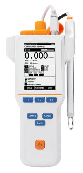
Figure 6
Screen icons explanation
1 System time. 2 Reading mode. 3 Measurement parameters. 4 Main measurement box. 5 Calibration information. 6 Sample ID. 7 User ID. 8 Operation tips. 9 Power information. 10 Reading states. 11 Soft function keys.
The instrument displays symbol identification that has the following functional implications:
Symbol explanation
No. | Symbol | Explanation |
1 | | Reading status, display the measurement status of reading, stable, locked each indicates that the processing, stable, and reading completed. |
2 | | Automatic temperature compensation |
3 |
| Manual temperature compensation |
4 | | Standard solution |
5 | | Standard solution for conductivity calibration |
6 | | Cell constant |
7 | | The reference temperature in EC measuring |
8 | | Temperature coefficiency |
9 |
| EC compensation mode |
10 | | Type of cell constant calibration |
11 | | Calibration time |
12 | | TDS factor |
13 | | Air pressure compensation in DO measuring |
14 |
| Salinity compensation in DO measuring |
15 | | User ID |
16 | | Sample ID |
17 | | Operation Tips |
18 |
| Resistivity, Unit MΩ·cm, kΩ·cm, Ω·cm |
19 | | Temperature, unit °C |
20 | | Power information |
21 |
| Charging |


Table 3
5.3 Function Key

Figure 7
Function keys explanation
No. | Key | Explanation | Note |
1 | | Power | Press to switch on/off |
2 | | Setting | Set the parameters and settings |
3 | | Cancel | Cancel the operation |
4 | | Enter | Confirm the option |
5 |
| F1 | Function key, Corresponds to the function options on the screen |
6 | | F2 | Function key, Corresponds to the function options on the screen |
7 | | F3 | Function key, Corresponds to the function options on the screen |


Table 4
5.4 Parameter Settings
When the meter is in the standby status or measuring status, press "Setting" to reset the instrument setting.

Figure
8 Instrument settings
5.4.1 Tutorial setting
For the first use, please follow the guide to settings the measurement parameters. After all the settings, press the "Enter" to return to the previous page.
5.4.2 Select parameters
Press "Setting"- "Select parameter" to select a parameter to calibrate and measure. It could select one measurement parameter from conductivity, TDS, salinity and resistivity every test.
5.4.3 Reading Mode Settings
The meter provides three reading modes, including continuous readings, auto readings, and timed readings.
• Continuous reading: The instrument displays real-time measurement results. User can end the measurement at any time and save the last result.
• Auto-reading: The measurement reached the balance, and the meter locked the reading result. The meter offers "Fast", "Medium", "Strict" and "Custom" four options for endpoint detection conditions.
• Time reading method: Timed Reading contains two kinds of timed reading methods: "Interval measurement" and "Timed measurement". "Interval Measurement" provides measurement results at interval time and timed reading provide measurement result after a set time.
Reading parameters settings
Stability Type | Conductivity | |
Fast | Stable time | 5s |
Fluctuation | 1.0% | |
Medium | Stable time | 8s |
Fluctuation | 0.4% | |
Strict | Stable time | 15s |
Fluctuation | 0.1% | |
Custom (Recommended value) | Stable time | 1 to 30s |
Fluctuation | 0.1~2% | |
Table 5
5.4.4 Conductivity Parameter Settings
5.4.4.1 EC calibration type
EC calibration type: Cal by Standards and input manually.
Cal by Standards: Cell constant is calibrated with standard conductivity standard solution.
Input manually: It allows user to set the cell constant.
5.4.4.2 Manual standard recognition
For neighboring standards, please choose the customization to perform calibration.
5.4.4.3 Conductivity electrode type
Conductivity electrode: Four conductivity cell constant 0.01, 0.1, 1, 10. The defaulted conductivity cell constant is 1. Users need to enter the cell constant value on the label of conductivity electrode for accurate measurement.
5.4.4.4 EC Reference temperature
Conductivity reference temperature: The conductivity of the solution is greatly affected by temperature, to make the conductivity measurement results at different temperatures comparable, the conductivity and temperature values at the time of measurement are usually recorded and converted into the conductivity value at a certain temperature through temperature compensation, which is the reference temperature.
When measurement parameter is conductivity, TDS or resistivity, the meter allows settings of 20.0°C, 25.0 °C reference temperatures; the default reference temperature is 25 °C.
When measurement parameter is salinity, the default reference temperature is 18 °C and cannot change.
5.4.4.5 Conductivity Compensation
EC Compensation Mode: Three different compensation modes can be used for various applications. The meter supports linear type, DI water type and Non-comp type.
1) Linear type: Linear compensation is usually used for the measurement of medium and high conductivity solutions. With linear compensation, you can set the temperature compensation coefficient, which defaults to 2.00%/°C (approximately the temperature compensation coefficient of a sodium chloride solution at 25°C). It allows user to set the temperature coefficient.
2) DI water type: DI water compensation is usually used for the measurement of pure water and ultrapure hydropower conductivity below 5μS/cm. It allows user to set the temperature coefficient.
3) Non-comp type: Non compensation is usually used to obtain the true conductivity value at the measured temperature.
5.4.4.6 TDS Parameter
The TDSF calibration type can be calibrated by standard solution or setting the TDS Factor. The TDS factor can be adjustable, and the default is 0.500. It allows user to calibrate the TDS Factor.
5.4.4.7 Salinity parameter
The meter supports both default salinity and seawater salinity measurement types.
Sea salinity mode: it indicates the nominal salinity value used to measure seawater salinity correction. The standard seawater salinity concentration adopted here is 3.500%, also written as 35 psu.
Default Salinity Mode: the salinity of common sample, which can be used to approximate the salinity of the measured solution.
5.4.5 Temperature Parameter Settings
The temperature unit of the meter is selectable in °C and °F.
Temperature compensation mode: ATC and MTC.
ATC means automatic compensation. Combination conductivity probes integrated with ATC probe.
MTC means manual compensation. It allows user to input the temperature.
5.4.6 Data Management Settings
5.4.6.1 Sample ID type
The instrument supports three setting methods of Sample ID: number order, time order, and manual.
• Number order: The sample ID No. is increasing with series number.
• Time order: The sample ID No. is increasing with sample measuring time. Format: Year/Y, Month/M, Day/D, Hour/H, Minutes/M, Second/S
• Manual: Manually set the sample ID No. It allows samples to manually enter the sample ID when saving or printing data.
5.4.6.2 Result Auto save
When this function is enabled, the meter saves the results when the reading is stable in the auto-reading and interval timed reading mode.
5.4.6.3 Data Overwrite
The meter provides 1000 sets of measurement results storage space. When this function is enabled, the results data that exceeds capacity will overwrite the old results data.
5.4.7 Output option
The data formats are GLP, STD Format, and Custom. It could select one data format to output the result.
5.4.8 User ID Settings
Set the user ID.
5.4.9 System Parameter Settings
5.4.9.1 System Date & Time
Settings of system date and time.
5.4.9.2 Buzzer setting
Users can set the key sound by this setting.
5.4.9.3 Brightness setting
Users can adjust the screen brightness by this setting.
5.4.9.4 Auto Power off
The meter provides auto shutdown function. When the meter is not using, the meter switches off automatically.
5.4.9.5 Restore Default
The meter supports "Restore Default" and "Restore Parameters".
"Restoring Default" will restore all meter parameters to the factory state. "Restoring parameters" will restore the measurement parameters to the factory state.
5.4.9.6 Software version
Users can find the software version information on the general setting page.
5.5 Conductivity Measurement
5.5.1 Cell Constant Input
Conductivity electrodes are precisely calibrated at the time of manufacture and marked with the exact cell constant. Before the measurement, press "Setting"- "EC Parameter"- "Electrode Constant" to enter the electrode cell constant.
5.5.2 Calibration Preparation
In general, conductivity electrodes need few calibrations. When the user gets an unexpected result, an electrode calibration is considerable.
Usually, single standard solution is required for calibration. For accurate measurement of sample conductivity above 50mS/cm, a two-point calibration is required. Two standards are required, a low conductivity standard and a conductivity standard close to the sample.
The meter provides universal standard group to automatic recognition. And allows the user to prepare the customized Standard groups.
5.5.3 Conductivity Calibration

Figure 9
Electrode cell constant calibration information

Figure 10
Electrode cell constant calibration result information
For conductivity electrodes with different cell constants, it is recommended to use the following conductivity standard solutions for calibration.
KCl standards to electrode cell constants
Cell constant (cm-1) | 0.1 | 1 | 10 |
KCl solution Concentration (mol/L). | 0.001 | 0.01 or 0.1 | 0.1 or 1 |
Table 6
The calibration process is as follows:
1. Press soft button F1 "Setting"- "EC Parameter".
2. Press the "Constant type" to select the "1".
3. Press "Cal. Type" to select the "Cal by Standards".
4. Prepare one or more standard conductivity solution (e.g.1413μS/cm conductivity solution).
5. Prepare a thermostatic bath, and set the temperature to (25.0±0.1) °C.
6. Place a standard conductivity solution in a thermostatic bath, and set the temperature to (25.0±0.1) °C.
7. Press the F2 "Calibrate" for one-parameter measurements or press the F2 "Calibrate"- "EC Calibration" for multi-parameter measurements.
8. Place the conductivity electrode into a standard solution.
9. When the conductivity and temperature reading (e.g.,1413μS/cm, 25.0°C) are stable, press the "Start".
10. If choosing one-point calibration, press "Enter" to end the calibration.
11. If choosing multi-points calibration (up to 3), press "Next Point" to calibrate the next standard solution.
12. The meter saves calibration data automatically.
 【TIPS】
The conductivity of the solution is greatly affected by temperature, it is recommended to use constant temperature water for calibration. Automatic or manual temperature compensation can also be optional when there is no water bath.
5.5.4 Conductivity Measurement

Figure 11
Conductivity measurement information
The measurement process is as follows:
1. Setting.
1) Set the parameters (e.g. conductivity).
2) Set the reading mode (e.g. continuous reading, auto-reading, or timed format).
3) Set the temperature compensation (e.g. linear compensation, temperature compensation coefficient 2.00%/°C).
4) Set the reference temperature (e.g. 25°C).
2. Rinse the conductivity electrode with DI water, dry out.
3. Put the measurement end of the electrode into the sample solution.
4. When the reading is stable, press "Enter" to enter into measurement status.
5. When the reading is stable, read the results.
6. During measurement, stored EC electrode in distilled or deionized water.
7. After measurement, rinse the EC electrode with deionized water thoroughly and put on the electrode protection cap.
5.6 TDS Measurements
TDS: Total dissolved solids refer to the total amount of all solutes in water, including the content of both inorganic and organic matter. In general, the higher the conductivity, the higher the salt, the higher the TDS.
5.6.1 TDS conversion factor
5.6.1.1 Low Concentration TDS Sample
For samples with relatively simple composition and low concentration, TDS of solution can be estimated by conductivity. Compared with weighing method, TDS estimation by conductivity is relatively simple and convenient with quite good accuracy. For potassium chloride and sodium chloride solutions below 5000 μS/cm, the TDS coefficient is approximately 0.5.
Therefore, 0.5 can be used as the TDS coefficient for approximate estimation in most situations.
The conversion factor adjusts process is as follows:
1. Press soft button F1 "Setting" -"TDS Parameter".
2. Select the TDSF CAL Type as the set TDS Factor.
3. Input the TDS factor as the desired TDS coefficient.
Conductivity to TDS Standard Solution
Conductivity μS/cm | TDS standards | ||
KCl(ppm) | NaCl(ppm) | 442(ppm) | |
23 | 11.6 | 10.7 | 14.74 |
84 | 40.38 | 38.04 | 50.5 |
447 | 225.6 | 215.5 | 300 |
1413 | 744.7 | 702.1 | 1000 |
1500 | 757.1 | 737.1 | 1050 |
2070 | 1045 | 1041 | 1500 |
2764 | 1382 | 1414.8 | 2062.7 |
8974 | 5101 | 4487 | 7608 |
12880 | 7447 | 7230 | 11367 |
15000 | 8759 | 8532 | 13455 |
80000 | 52168 | 48384 | 79688 |
Table 7
1, 442 indicated the solution contains 40% Na2SO4, 40% NaHCO3, 20% NaCl.
2, The values listed in the table are values at 25°C.
For KCl and NaCl solutions below 5000 μS/cm, the TDS coefficient is about 0.5, so 0.5 can be used as an approximation in most cases.
5.6.1.2 High Concentrations TDS Sample Measurement
For samples with simple components and higher concentrations, such as high concentrations of NaCl solution, TDS factor re-calibration is needed.
For TDS measurements, the user may need to correct the TDS conversion factor by TDS standard.
The conversion factor calibration process is as follows:
1. Setting.
1) Set the parameters (e.g. TDS).
2) Press soft button F1 "Setting" -"TDS Parameter".
3) Select the TDSF CAL Type as the set Cal by STD.
4) Set the reference temperature (e.g. 25°C).
2. Prepare TDS Standard.
3. Place a standard conductivity solution in a thermostatic bath, and set the temperature to (25.0±0.1) °C.
4. Rinse the conductivity electrode with DI water, dry out.
5. Put the measurement end of the electrode into the sample solution.
6. Press the F2 "Calibrate"-"TDS Calibration".
7. Set the STD value as the sample STD value.
8. After the TDS and temperature reading (708ppm, 25.0°C) are stable, press the "Start".
9. If choosing one-point calibration, press "Enter" to end the calibration.
10. If choosing multi-points calibration (up to 3), press "Next Point" to repeat the operation.
11. The meter saves calibration data automatically.

Figure 12
TDS coefficients calibration
5.6.1.3 Complex TDS Sample Measurement
For samples with complex compositions, the accuracy of TDS measurements can be improved by re-determination by laboratory methods and manual input of TDS coefficients. When the composition or concentration of the sample to be measured changes significantly, it is recommended to recalibrate the TDS coefficient.
The conversion factor calibration process is as follows:
1. Rinse the electrode with DI water. Put the measurement end of the electrode into the sample solution and set the temperature at (25.0±0.1) °C.
2. Using weighing method to determine the TDS.
3. Calculate the TDS coefficient.
4. Press soft button F1 "Setting" - "TDS Parameter".
5. Select the TDSF CAL Type as the set TDS Factor.
6. Input the TDS factor as the desired TDS coefficient.
5.6.2 TDS Measurements
Users can switch the measurement parameter to TDS measurement by pressing Conductivity/TDS measurement box on the screen.
5.7 Salinity Measurement
The instrument can be used to determine the salinity of sodium chloride. The salinity of sodium chloride can be used to approximate the salinity of the solution being measured. By measuring the conductivity of the sample, the mass percentage of the corresponding sodium chloride solution can be calculated to convert the sodium chloride salinity.
Users can switch the measurement parameter to salinity measurement by pressing Conductivity/TDS measurement box on the screen. The detail refers to the measurement method of conductivity salinity measurement.
5.8 Resistivity Measurement
Resistivity and conductivity are reciprocal to each other, and conductivity can be measured at the same time when measuring resistivity.
Users can switch the measurement parameter to resistivity measurement by pressing Conductivity/TDS measurement box on the screen. The detail refers to the measurement method of conductivity measurement.
5.9 Data Management
Press "Data" to view the detail of results.
The meter stores the measurement results independently according to the measured parameters. The meter provides data Storage 500 sets for each parameter (EC/Resistivity/TDS/Salinity).
The user can press "Delete" into the delete menu. It allows users to select the parameter data or all data to delete.
The user can view the data filter by parameter, locate No. or stored date. By the filter setting, press "Enter" to look up the data. The filter data shows in a graph. Press "←" and "→" to choose data. User can choose one and press "Enter" key to see the detail result. Users can press "Operate" to the operation menu. In the operation menu, it allows to delete current result, output the current result, output matched result and output all result.

Figure 13
Results setting view

Figure 14
Results data graph

Figure 15
Measurement result output settings
The output format is followed:
****************************************
Report Title
----------------------------------------
Measure Time:2021/01/31 16:12:16
Operator: Operator 1
Model: EC310F Conductivity Meter
Serial Number:
SW Version: Ver 1.00
----------------------------------------
.............................SAMPLE INFO
Sample ID: Sample 1
..........................ELECTRODE INFO
Cond EC ID: Cond Electrode
..............................CALIB INFO
Calib Operator: REX Team
Calib Time: 2021/01/31 15:40:13
Calib Num: 3
............................CALIB RESULT
STD 1: 84uS/cm 84uS/cm 25.0c
STD 2: 1413uS/cm 1413uS/cm 25.0c
STD 3: 12.88mS/cm 12.88mS/cm 25.0c
Cell Constant 1: 1.000
Cell Constant 2: 1.000
Cell Constant 3: 1.000
..............................BRIEF INFO
Reading Mode: Timed Reading
Stable Type: Medium
Temp Comp Type: ATC
Cond Comp Type: Linear
..................................RESULT
Result: 0.000ppm
Signal Value: 0.000uS/cm
Temp Value: 25.0c
----------------------------------------
----------------------------------------
Signature:
6. Maintenance/Troubleshooting
6.1 Meter Maintenance
The correct use and maintenance of the instrument can ensure the accurate and reliable performance of the instrument. Additionally, exposure to chemicals or harsh use environments can affect performance.
• If the meter is not used for a long time, please disconnect the power supply.
• The electrode socket of the instrument must be kept clean and dry, and should not be in contact with acid, alkali, and salt solutions.
• Keep the meter and accessories clean and away from acids, alkalis, and any corrosive solutions/gases.
• Users can clean the meter surface with clean waters and detergent.
• When the meter is transported, please follow the instructions:
• Please remove all connected cables.
• Please remove the electrode holder.
• Please use original packaging in the long-distance transport to avoid damage.
6.2 Electrodes Maintenance
For more detailed information, please refer to the electrode instruction manual.
6.3 Battery Maintenance
The instrument uses a built-in lithium battery. The battery takes 4 hours to fully charge. Follow the below instruction to maintain battery:
• When the meter is turned on and not charged, the power light flashes four times when the power flashes once when the power is 25% and is 100%.
• When the meter switches off, the power light keeps the lighting for a full charge.
Precautions for the use of lithium batteries:
• Keep the meter away from the high-temperature environment.
• Keep away from water.
• Keep away from flammable and explosive substances.
• Please charge for 15 minutes if not in use for a long time.
• Please stop charging in time after fully charged.
• Continuous charging may result in decreased battery life.
• Please charge and discharge it every 3 months to extend the life of the lithium battery.
6.4 Troubleshooting
Phenomenon | Probable reasons | Solutions |
1. No Display | Damage to the meter. | Replace or repair as required. |
2. Incorrect conductivity measurement | 1. The electrode is out of service life. 2. The electrodes are not calibrated or are calibrated incorrectly. | 1. Replace the electrodes. 2. Recalibrate the electrode or replace the standard solution. |
Table 8
If the meter still does not work, please contact your local dealer for further assistance.
7. Technical Supports
Accessories
Please refer to the accessories table for purchasing recommendations.
Meter accessories
Name | Description |
DJS-1VTC conductivity electrode | Conductivity, TDS Measurement Probe |
Conductivity solution 1413 μS/cm | Standard solution |
Table 9
8. Appendixes
Appendix 1
Approximate concentrations of KCl solutions and their conductivity values relationship
T(°C) | 84μS/cm | 1413μS/cm | 12.88mS/cm |
5 | 53.02 | 896 | 8.22 |
10 | 60.34 | 1020 | 9.33 |
15 | 67.61 | 1147 | 10.48 |
20 | 75.80 | 1278 | 11.67 |
25 | 84.00 | 1413 | 12.88 |
30 | 92,19 | 1552 | 14.12 |
35 | 100.92 | 1696 | 15.39 |
Table 10