
Get Price
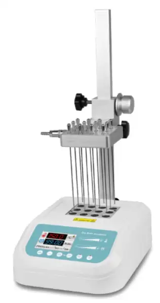
Concentrator BCON-107
A sample concentrator is mainly used for the concentration or preparation of bulk samples (such as drug screening, hormone analysis, liquid phase, and sample preparation in mass spectrometry). Working principle: By blowing nitrogen into the surface of the heated sample, the solvent in the sample is quickly evaporated and separated, thereby achieving the...
- Wide temperature control range up to 150°C.
- Equipped with an air chamber and a special adjustable stand, nitrogen blowing can be achieved.
- Simple or programmed temperature control mode, making the experiment more convenient.
- Compact structure, easy to use in narrow spaces.
- Up to 3-Year Product Warranty
- US & EU Compliance Standards
- Door-to-Door Shipping
Technical Specifications
Detailed operating and construction parameters for this model.
| Model | BCON-107 |
| Temp. Control Range | R.T.+5°C~150°C |
| Temp. Setting Range | 5°C~150°C |
| Time Range | 1min~99h59m (00:00 is continued) |
| Block temp. Stability@40~100°C | ±0.5°C |
| Block temp. Stability@>100°C | ±1°C |
| Block Temp. Uniformity@40°C | ±0.3°C |
| Block Temp. Uniformity@>40°C | ±0.5°C |
| Temp. Display Accuracy | 0.1°C |
| Heating Speed | <15min(20°C-150°C) |
| Needle Plate Max. Lift Stroke | 285mm |
| Gas-in Joint Outer Diameter | Φ7mm |
| Nitrogen Pressure | <0.1MPa |
| Nitrogen Flow Rate | 0~10L/min |
| Needle Length | 150mm |
| Sample Capacity | 1 standard block |
| Voltage | AC 220V/AC 110V 50Hz/60Hz |
| Power | 200W |
| Fuse | 250V, 2A/3A, Φ5x20 |
| Dimension(WxDxH) | 285x225x95 |
| Net Weight (kgs) | 2.48kgs |
Product Features
Key design, performance, usability, and safety advantages.
Accessories For Purchase View compatible optional accessories and additional items available separately.
| Images | Spec | Dia. of Hole | Name | Block Dimension |
 | 6 mm x 12 | 6.5 mm | Circular base | 95.5 x 76.5 x 50 mm |
 | 7 mm x 12 | 7.5 mm | Circular base | 95.5 x 76.5 x 50 mm |
 | 10 mm x 12 | 10.5 mm | Circular base | 95.5 x 76.5 x 50 mm |
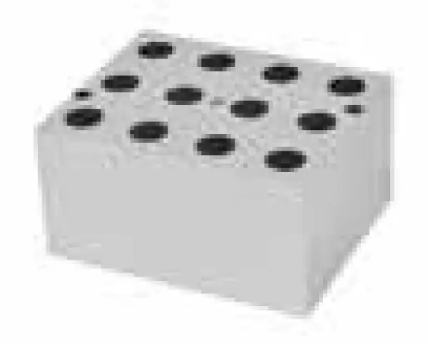 | 12 mm x 12 | 12.5 mm | Circular base | 95.5 x 76.5 x 50 mm |
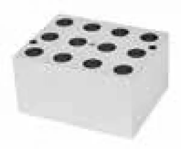 | 13 mm x 12 | 13.5 mm | Circular base | 95.5 x 76.5 x 50 mm |
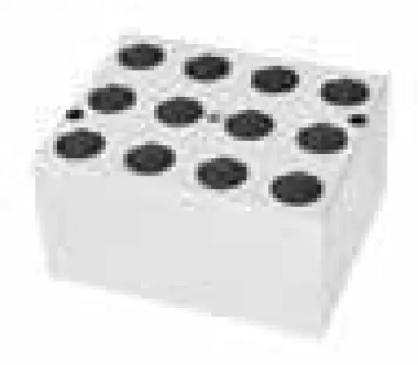 | 15 mm x 12(7ml Centrifuge tube) | 15.5 mm | Circular base | 95.5 x 76.5 x 50 mm |
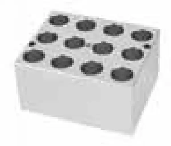 | 16 mm x 12(10ml/15ml Centrifuge tube) | 16.5 mm | Circular base | 95.5 x 76.5 x 50 mm |
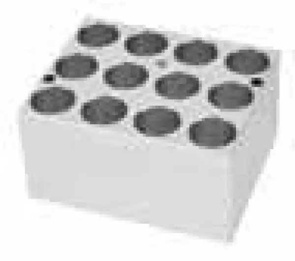 | 19 mm x 12 | 19.5 mm | Circular base | 95.5 x 76.5 x 50 mm |
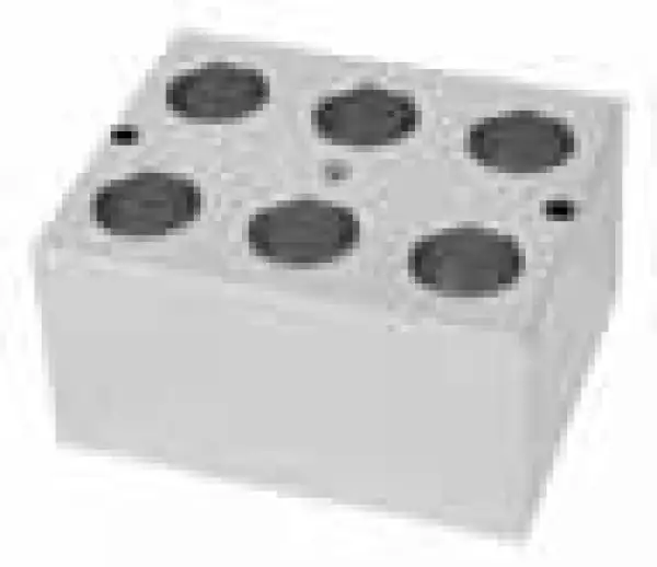 | 20 mm x 6 | 20.5 mm | Circular base | 95.5 x 76.5 x 50 mm |
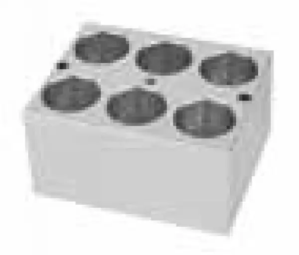 | 26 mm x 6 | 26.5 mm | Circular base | 95.5 x 76.5 x 50 mm |
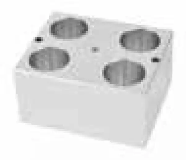 | 28 mm x 4(50ml Centrifuge tube) | 28.5 mm | Flat bottom | 95.5 x 76.5 x 50 mm |
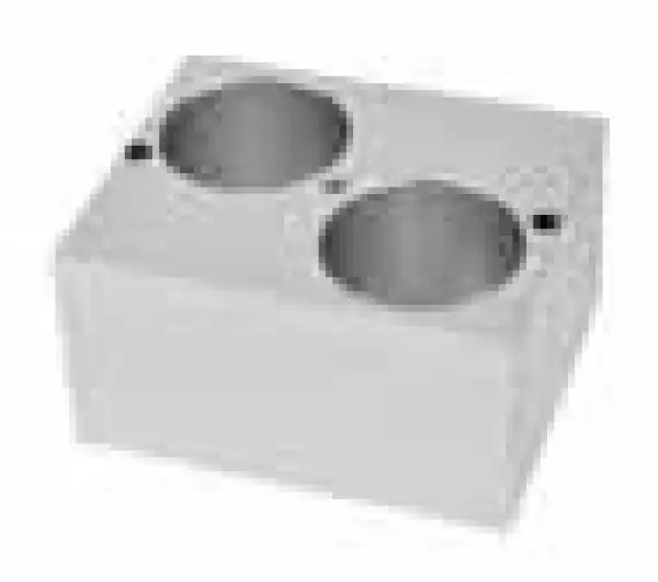 | 40 mm x 2 | 40.5 mm | Circular base | 95.5 x 76.5 x 50 mm |
 | 0.5 ml x 12 | 8 mm | Cone base | 95.5 x 76.5 x 50 mm |
 | 1.5 ml x 12 | 10.8 mm | Cone base | 95.5 x 76.5 x 50 mm |
 | 2.0 ml x 12 | 10.8 mm | Circular base | 95.5 x 76.5 x 50 mm |
 | 0.2 ml x 12 | 6.1 mm | Cone base | 95.5 x 76.5 x 50 mm |
| Customized | Customized | Customized | Customized |
Operating Manual View instructions, operating procedures, safety information, and maintenance guidance.
1. Safety Warnings and Guidelines
1.1 Important Operation Information of The Security
1.2 Security
1.3 Instruments Maintenance
2. After-sales service
3. Introduction
4. Specifications
5. Basic operating instructions
6. Operation Guide
7. Error Analysis and Trouble Shooting
1. Safety Warnings and Guidelines
1.1 Important Operation Information of The Security
Users should have an entire conception of how to use the instrument properly before operating it. Please read this operation manual carefully before using the instrument.
 No one is allowed to operate the instrument without reading the manual. If you do not operate according to the instructions in the manual, the instrument may cause accidental injury during operation, and electric shock may occur. Please read the following safety tips and instructions carefully and implement all precautions contained within.
1.2 Security
The following basic safety precautions must be observed during all operations, maintenance, and repairs of this instrument. Failure to comply with these measures or the warnings noted elsewhere in this manual may affect the protection provided by the instrument and the intended use of the instrument.
This product is a normal and an indoor using instrument, meet the standards of normal equipment of GB9706.1 Class I-B.
Before operation, read the manual carefully. These units are designed for using in the laboratory environments by who're knowledgeable in safe laboratory practices.
The operator should not open or repair the instrument by himself. Otherwise, the instrument will lose the qualification of repair guarantee or cause accidents. The company will repair the instrument based on warranty description.
Before connecting the power supply, make sure that the voltage of the power supply is consistent with the voltage required by the instrument. And ensure that the rated load of the power socket is not less than the requirements of the instrument.
If the power cord is damaged, it must be replaced. When replacing, the power cord must be replaced with the same type and specification. Do not press anything on the power cord when using this instrument. Do not place the power cord where people move around.
Be sure to hold the plug when plugging or unplugging the power cord. Make sure the plug is fully inserted into the socket when inserting it, and do not pull hard on the power cord when pulling out the plug.
 The temperature of metal block and top cover shell may be very high during the operation. There may be scald or boiling of the liquid. It is strictly prohibited any part of the body touching the instrument.
Pay attention to the high temperature!
 This instrument should be placed in a place with low humidity, less dust, away from water sources, and away from direct sunlight and strong light sources. The room should be well ventilated, free of corrosive gases or strong magnetic fields, and away from heaters, stoves, and all other heat sources. Do not place the instrument in a humid or dusty place.
The power should be turned off when stopping working. When the instrument is not used for a long time, the power plug should be unplugged and the instrument should be covered with a soft cloth or plastic paper to prevent dust from entering.
Under the following circumstances, you should immediately unplug the instrument from the power socket and contact the supplier or ask trained maintenance personnel to handle it:
• There is some liquid flowing into the instrument;
• Drenched or fire burned;
• Abnormal operation: such as abnormal sound or smell;
• Instrument dropping or outer shell damaged;
• The function has obviously changed.
1.3 Instruments Maintenance
The well in the block should be cleaned by the cloth stained with alcohol to assure good heat translation between the block and the test tube and no pollution. If there are smutches on the instrument, clean them with cloth.
Power off when cleaning the instrument.
Do not drop the clean fluid in the well when cleaning.
Corrosive clean fluid is strongly prohibited.
2. After-sales service
Warranty content
Within a month from the delivery date, the cause of failure due to material and manufacturing defects, the Company will be responsible for the guarantee replacement
Within 12 months from the delivery date, the cause of failure due to material and manufacturing defects. The company will prove to be defective instruments selected for repair or replacement
The product must be sent to the maintenance department of the company by the user. The freight will be borne by the user. The Company will bear the return shipping costs.
Over the warranty period, the Company will receive appropriate maintenance costs.
3. Introduction
BCON-107 & BCON-108 sample concentrator is mainly used for the concentration or preparation of bulk samples (such as drug screening, hormone analysis, liquid phase, and sample preparation in mass spectrometry). Working principle: By blowing nitrogen into the surface of the heated sample, the solvent in the sample is quickly evaporated and separated, thereby achieving the purpose of anaerobic concentration of the sample and keeping the sample more pure. Using a sample concentrator instead of a commonly used rotary evaporator for concentration can concentrate multiple samples at the same time, saving time and efficiency.
This product has the following features:
• Wide temperature control range up to 150°C.
• Equipped with an air chamber and a special adjustable stand, nitrogen blowing can be achieved.
• Simple or programmed temperature control mode, making the experiment more convenient.
• Compact structure, easy to use in narrow spaces.
• High-definition color screen display, providing an intuitive and clear visual experience.
• Real-time temperature and constant temperature countdown time.
• With metal blocks, samples are protected from contamination.
• The metal block is easy to replace, easy to clean and sterilize.
• Built-in over-temperature protection device to keep you and experiments safe.
• Temperature deviation calibration, more accurate temperature control.
• Fault code display function, the system has its own fault detection function.
• The buzzer sound can be turned off, making the experiment quieter.
• Sliding operation and touch buttons, novel and fashionable.
• The height of the air chamber can be adjusted to make it suitable for different test tubes, and the standard air needle length is 150mm.
• When concentrating toxic solvents, the entire system can be placed in a fume hood.
• The heater causes the sample to be rapidly heated to the evaporation temperature, and at the same time, the gas is blown to the surface of the solution through the gas needle, which promotes the rapid evaporation of the solution and the concentration of the sample.
• Unique patented design for air channel control system, enhances air tightness and reduces potential leakage; easy to operate, lift/press air needle to realize channel switch; the switching status of each channel is clear at a glance.
4. Specifications
1. The normal working condition:
The room temperature:5C 40C
The relative humidity:≤70% The using power:AC220V 50Hz
2.Basic Parameters and Performance
Model | BCON-107 | BCON-108 |
Temp. Control Range | R.T.+5°C~150°C | R.T.+5°C~150°C |
Temp. Setting Range | 5°C~150°C | 5°C~150°C |
Time Range | 1min~99h59m (00:00 is continuous operation) | 1min~99h59m (00:00 is continuous operation) |
Block temp. Stability@40 ~ 100°C | ±0.5°C | ±0.5°C |
Block temp. Stability@>100°C | ±1°C | ±1°C |
Block Temp. Uniformity@40°C | ±0.3°C | ±0.3°C |
Block Temp. Uniformity@>40°C | ±0.5°C | ±0.5°C |
Temp. Display Accuracy | 0.1°C | 0.1°C |
Heating Speed | ≤15min(20°C~150°C) | ≤15min(20°C~150°C) |
Needle Plate Max. Lift Stroke | 285mm | 285mm |
Gas-in Joint Outer Diameter | Φ7mm | Φ7mm |
Nitrogen Pressure | ≤0.1MPa | ≤0.1MPa |
Nitrogen Flow Rate | 0~10L/min | 0~10L/min |
Needle Length | 150mm | 150mm |
Sample Capacity | 1 standard block | 2 standard blocks |
Voltage | AC 220V/AC 110V 50Hz/60Hz | AC 220V/AC 110V 50Hz/60Hz |
Power | 200W | 400W |
Fuse | 250V,2A/3A,Φ5x20 | 250V,3A/6A,Φ5x20 |
Dimension(WxDxH) | 285x225x95 | 285x225x95 |
Net Weight(kgs) | 2.48kgs | 2.64kgs |
Table 1
3. Optional blocks
Block # | Hole diameter | Number of test tubes | Block Size (mm) |
DT01A | 6mm | 12 | 95.5x76.5x50 |
DT02A | 7.5mm | 12 | 95.5x76.5x50 |
DT03A | 10.5mm | 12 | 95.5x76.5x50 |
DT04A | 12.5mm | 12 | 95.5x76.5x50 |
DT05A | 13.5mm | 12 | 95.5x76.5x50 |
DT06 | 15.5mm | 12 | 95.5x76.5x50 |
DT07 | 16.5mm | 12 | 95.5x76.5x50 |
DT08 | 19.5mm | 12 | 95.5x76.5x50 |
DT09 | 20.5mm | 6 | 95.5x76.5x50 |
DT10 | 26.5mm | 6 | 95.5x76.5x50 |
DT11 | 28.5mm | 4 | 95.5x76.5x50 |
DT12 | 40.5mm | 2 | 95.5x76.5x50 |
DT13A | 8mm(0.5ml) | 12 | 95.5x76.5x50 |
DT14A | 10.8mm(1.5ml) | 12 | 95.5x76.5x50 |
DT15A | 10.8mm(2.0ml) | 12 | 95.5x76.5x50 |
DT16A | 6.1mm(0.2ml) | 12 | 95.5x76.5x50 |
DT19* | customized | customized | customized |
Table 2
5. Basic operating instructions
This chapter introduces the instrument's mechanical structure, keyboard and each key's function and some preparations before power on. You should be familiar with this chapter before the instrument is first operated.
1. Structure Description
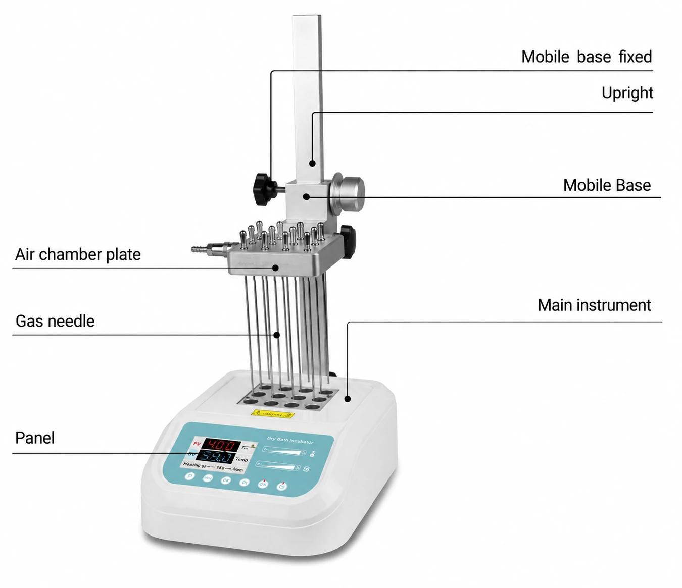
Figure 1
2. Operation panel
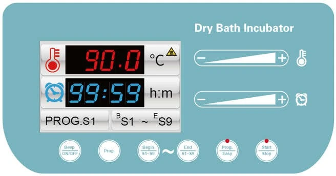
Figure 2
3. Display instructions
1. The red font displays the set temperature
2. The blue font shows the set time
3. Node number (S1)
4. High temperature hazard warning
5. Starting node (S1)~Ending node (S9)
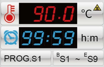
Figure 3
4.Indicator light description

Figure 4
When the indicator light is on, the temperature control mode is Prog mode; when it is off, the temperature control mode is Easy mode;
The indicator light is on when running and off when stopped;
5. Temperature control mode description
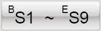 Program mode starts running from the starting node and ends at the end
Node.
 Easy mode, only selected nodes will be run.
6. Operation Guide
1. Button description
 Press and hold for 3 seconds and the buzzer will beep once, which is used to turn on or off the buzzer sound;
 Touch this key to switch the current step PROG.S1 ~ PROG.S9;
 Touch this key to switch the starting step BS1 ~ BS9; (Note: the starting step must not be greater than the ending step)
 Touch this key to switch the end steps ES1 ~ ES9; (Note: the end step must not be smaller than the start step)
 Touch this key to switch between simple or program mode;
 Touch this key to run or end temperature control;
2. Slider description
Temperature slider operating instructions 
Slide from left to right to increase the temperature value. You can also touch the "+" key to increase the temperature value; at the same time, the parameter font changes to yellow.
Slide from right to left to decrease the temperature value. You can also touch the "-" key to decrease the temperature value; at the same time, the parameter font changes to yellow.
Time slider operation instructions 
Slide from left to right to increase the time value. You can also touch the "+" key to increase the time value; at the same time, the parameter font changes to yellow.
Slide from right to left to decrease the time value. You can also touch the "-" key to decrease the time value; at the same time, the parameter font changes to yellow.
Reminder! When the time is set to 00:00, it means that the time running value is ∞, and the instrument continues to run.
3. Temperature error calibration
The temperature of the Instrument has been adjusted before it is sold out. In case there is deviation between the actual temperature and the displayed temperature, you can do as follow for temperature calibration.
Notice! In order to ensure the accuracy of the temperature, this instrument uses a three-point temperature calibration method, that is, a three-point temperature synchronous linear calibration method of 40°C, 100°C and 140°
C. After three-point temperature linear calibration, the system ensures that the temperature accuracy at other temperature points is ≤±0.5°C.
When calibrating the temperature, the ambblockient temperature and block temperature must be lower than 35°C.
The specific operation method is as follows:
3.1 After the instrument is turned on, enter the waiting interface. At this time, observe the temperature of the temperature display window and confirm that its temperature value should be less than 35 °C. If the temperature is higher than 35 °C, wait for the temperature to drop to 35°C, and then operate according to the following methods.
3.2 Inject paraffin oil into a tapered hole in the center of the block, and put a thermometer in the tapered hole (the accuracy of the thermometer is required to be 0.1°C, and the thermometer bulb must be completely immersed in the tapered hole), the upper part of the block use insulation materials to isolate from the environment.
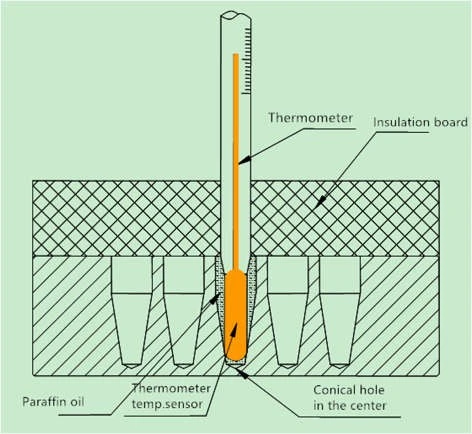
Figure 5
3.3 Simultaneously press and hold the "Begin/S1~S9" and "End/S1~S9" keys to enter the temperature calibration interface. The temperature display window displays the instant temperature, the ADJ... icon appears, and the temperature rises to 40.0°C automatically. When the temperature rises to a constant temperature of 40.0°C, the decimal place starts to flash, waiting for the temperature calibration value of 40°C. After 20 minutes of constant temperature, read the actual temperature of the thermometer.
Notice! In order to ensure the accuracy of temperature calibration, it is recommended that users read the measured temperature after 20 minutes of constant temperature!
If the value read by the thermometer is 39.6°C, use the slider to modify the temperature value in the temperature display window to make the temperature value 39.6, and press the "Start/Stop" key to confirm the input value.
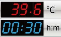
Figure 6
3.4 Then the instrument automatically heats up to 100°C and waits for the temperature calibration value to be input after the constant temperature of 100°C. It is also required to read the actual temperature of the thermometer after 20 minutes of constant temperature.
Notice! In order to ensure the accuracy of temperature calibration, it is recommended that users read the measured temperature after 20 minutes of constant temperature!
If the value read by the thermometer is 101.5°C, use the
slider to modify the temperature value in the temperature display window, make the temperature value 101.5, press the "Start/Stop" key to confirm the input value.
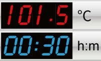
Figure 7
3.5 Then the instrument automatically heats up to 140°C and waits for the temperature calibration value to be input after the constant temperature at 140°C. It is also required to read the actual temperature of the thermometer after 20 minutes of constant temperature.
Notice! In order to ensure the accuracy of temperature calibration, it is recommended that users read the measured temperature after 20 minutes of constant temperature!
If the value read by the thermometer is 140.5°C, use the slider
to modify the temperature in the temperature display window, make the temperature value 140.5, press the "Start/Stop" key to confirm the input value. In this way, the three-point temperature calibration has been completed, and it will automatically exit the temperature calibration interface and return to the waiting interface.
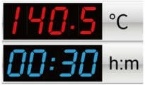
Figure 8
3.6 Attention! During the three-point temperature calibration process, press and hold the "Begin/S1~S9" and "End/S1~S9" keys at the same time to exit the temperature calibration program. The temperature value is invalid!
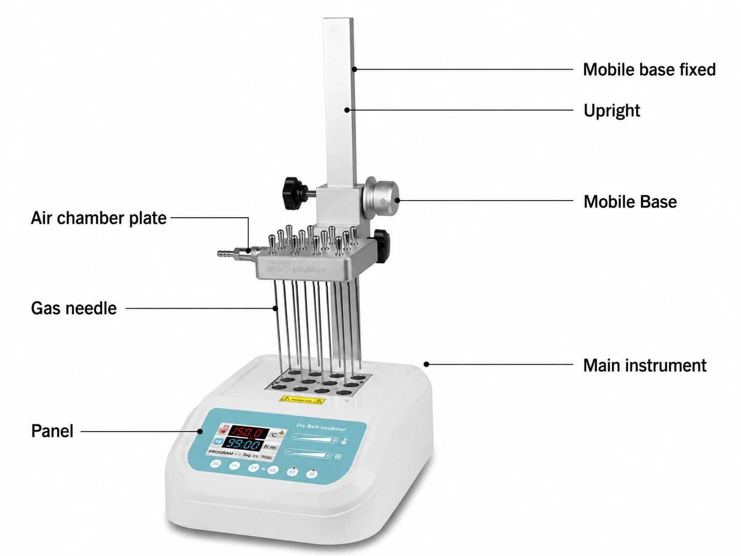
Figure 9
Installation steps:
1. Place the main instrument on the workbench steadily and firmly.
2. Insert the column into the square hole of the column holder at the back of the host, insert the column completely to the end, then screw the knob into the column holder, and tighten the knob to fix the column.
3. Screw the fixed knob of the movable seat into the threaded hole on the left side of the movable seat as shown in the figure, do not tighten it first, then hold the knob of the movable seat with your left hand, turn the adjusting handwheel counterclockwise with your right hand, and the movable seat will rise to Tighten the knob with the left hand at the desired position, then fix the movable seat. Turn the adjusting handwheel clockwise, and the movable seat will descend.
Note: When raising and lowering the mobile base, you must use your left and right hands to operate the fixed knob and adjustment handwheel of the mobile base at the same time.
4. Pre-screw the air chamber fixing knob into the threaded hole on the left side of the movable seat as shown in the figure. Please do not screw it completely, and then align the air chamber insert of the air chamber with the corresponding hole in the front of the movable seat. Pay attention to the air chamber. After the positioning pin is matched with the air chamber, after the air chamber inserting column is fully inserted, tighten the air chamber fixing knob.
Gas needle installation
a) Make the hole at the front side of the air needle completely sealed and fixed in the air chamber plate. If some holes in the module are not used, please turn off the throttle so that the air source will not be wasted.
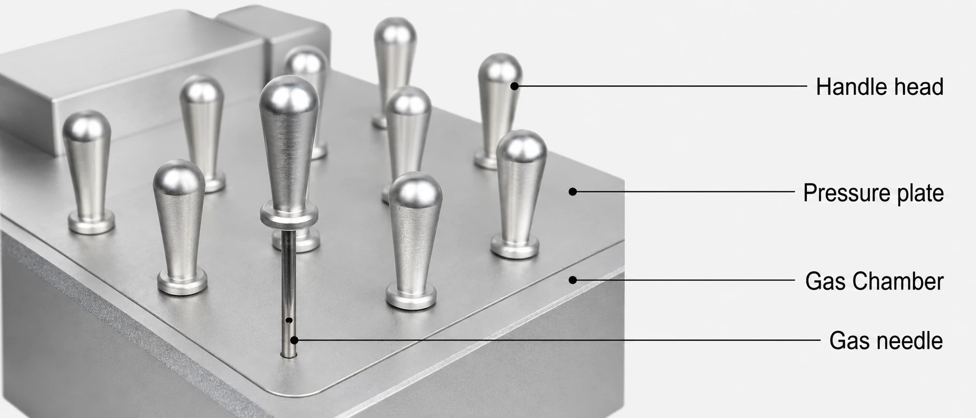
Figure 10
b) After installing the gas needle, turn over the gas chamber, insert the gas chamber into the movable seat, and fix the gas chamber with the gas chamber fixing knob.
c) There is a quick connection function at the gas joint, so that the user can conveniently and quickly switch on and off the gas source. The operation is as follows:
As shown in the figure below, press the part 2 (connector) by hand, and then align the plug with 1 (intake nozzle) to the A direction. The spring part in the connector will automatically clamp 1 (intake nozzle). When you need to get the air pipe out of the gas distribution chamber, just hold down 2 (connector) and push it hard to B, and the spring part in the connector will automatically detach from 1 (intake nozzle).
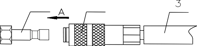
Figure 10
1. Intake nozzle
2. Connector
3. Gas tube
d)Hold the fixed knob of the moving seat with the left hand, loosen the knob, and turn the adjusting handwheel with the right hand to lower the air chamber with the air needle installed,so that the air needle is inserted about 10mm above the liquid in the test tube. Tighten the knob of the movable seat to fix the movable seat.
Reconnect the air source as needed.
Note: The pressure of the input gas should not be greater than 0.08Mpa. Excessive pressure of the gas source will make the gas chamber poorly sealed and leak the gas chamber, thereby wasting the gas source. When the number of gas needles used is less than 16, the gas pressure should not be greater than 0.04Mpa.
Nitrogen flow control valve installation
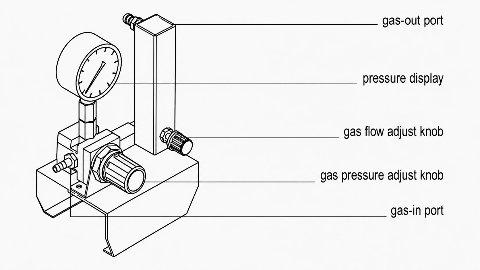
Figure 11
1) Composition of nitrogen flow regulating valve
Pull out the pressure adjustment knob, turn the knob clockwise to increase the pressure,otherwise, reduce the pressure to close. Press the knob to lock the knob, and the pressure cannot be adjusted at this time. Turn the flow adjustment knob counterclockwise to increase the flow, otherwise reduce the flow to close.
Note: The nitrogen flow regulating valve and air filter are optional accessories, which are choosed by customers according to their needs.
2)Nitrogen flow control valve installation
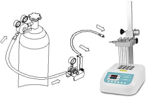
Figure 12
As shown in the figure above, connect the outlet of the nitrogen flow regulating valve with the inlet of the air chamber of the main instrument with a short gas pipe (about 1.5m long), and connect the inlet of the nitrogen flow regulating valve and the outlet of the nitrogen cylinder with a long gas pipe (about 3m).
Note: Slowly open the valve of the nitrogen bottle to control the outlet pressure between 0.1MPa to 0.2MPa, and then open the valve adjusting knob to keep pressure value at 0.02MPa. According to the number of holes, we can adjust the pressure appropriately (usually between 0.02MPa and 0.05MPa optional).
Metal block replacement
1. Use an Allen wrench to completely unscrew the 2 screws fixing the metal block in a counterclockwise direction.

Figure 13
2. Tighten the M4 threaded part of the handle clockwise to the M4 threaded hole in the middle of the metal block need to be replaced.
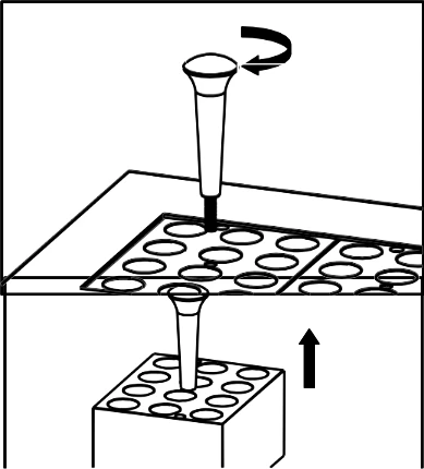
Figure 14
3. Pull up the upper end of the handle with your hand and take out the metal block.
4. Unscrew the handle and fix it on the metal block of another model to be replaced. Then place it on the corresponding position of the instrument, and fix the newly replaced metal block on the instrument in a clockwise direction with an Allen key.
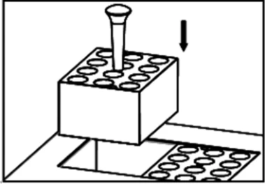
Figure 15
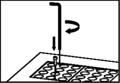
Figure 16
7. Error Analysis and Trouble Shooting
Failure analysis and treatment methods
No. | Fault phenomenon | Cause analysis | Recovery processing |
1 | No signal on the display when power on | No power | Check the connection of power |
Broken fuse | Exchange fuse | ||
Broken switch | Exchange the switch | ||
Others | Contact to the seller | ||
2 | The actual and display temperature are quite different | Broken sensor or loose contact of the block | Contact to the seller |
3 | The temperature display window displays "ERR.1"/"ERR.2" | Broken sensor or room temperature below zero. | Contact to the seller |
4 | No heating of the block | Broken sensor. | Contact to the seller |
Thyristor damage | |||
Broken heater | |||
5 | Touch the slider does not work | Poor cable contact | Contact to the seller |
Table 3