Get Price
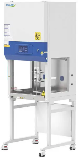
Class II Biosafety Cabinet BCBS-1103
- 1. 7-inch large touch color display: touch operation, real-time and clearer display of various values of the safety cabinet, dynamic air flow pattern diagram, fault alarm sound and light prompt.
- 2. The power-on password can be set to prevent mis-operation by irrelevant personnel.
- 3. Automatically adjust the wind speed.
- 4. Power-off memory, restore the state before power-off, and have a visual reminder to alarm.
 Get Quote
Specifications
| Model | BCBS-1103 |
| External Size(W*D*H) | 700*700*2000mm |
| Internal Size(W*D*H) | 600*500*540mm |
| Work Surface Height | 750mm |
| Max Opening Height | 350mm |
| Safe OperationOpening Height | 200mm |
| Airflow Volume: Inflow | 230m3/h(135cfm) |
| Airflow Volume: Down flow | 65%: 428 m3/h(252cfm) |
| Airflow Volume: Exhaust | 35%: 230m3/h(135cfm) |
| Front Window | Manual and electric, glass thickness> 5mm, anti-ultraviolet |
| ULPA Filter | 2pcs, filtration efficiency for 0.12um particles≥99.9995% |
| Illumination | >1000Lux |
| Noise | EN12469<65dB |
| Display | Color Touch Screen |
| European Standard Socket | 230V, 3A |
| Power Supply | AC 230V, 50/60Hz |
| Rated Power | 950W |
| Alarm | Alarm for abnormal wind speed, alarm for glass door not at safe height, alarm for abnormal power failure |
| Motor | DC single fanAdjustable speed, high efficiency, low power |
| Material | Working Area: 304 stainless steel, side window glass;Frame and decorative plate: cold-rolled steel with anti-bacteria powder coating |
| LED Lamp | 8W*2 |
| UV Lamp | 15W |
| Standard Accessory | Cabinet*1, Base stand*1, LED lamp*2, UV lamp*1, Drain ball valve*1, European Standard Socket*2 |
| Optional Accessory | Arm rest, Formalin fumigation sterilizer, Infrared sterilizerS.S. water tap*2, S.S. gas tap*2 |
| Package Size (W*D*H) | 850*880*1550mm |
| Gross Weight | 170kg |
Features
2. The power-on password can be set to prevent mis-operation by irrelevant personnel.
3. Automatically adjust the wind speed.
4. Power-off memory, restore the state before power-off, and have a visual reminder to alarm.
5. Side windows on both sides for easy observation.
6. The operation area is integrally formed, which is easy to disassemble and clean.
7. A breeze speed sensor is equipped at the working area and the outer exhaust air outlet to detect the wind speed in real time.
8. It can be used both manually and electrically, and the glass door can be pulled down to close the front window when the power is off.
9. The cabinet is separated from the base. The height of the adjustable base can be customized.
10. Interlocking function: UV lamp and front window; UV lamp and fan, fluorescent lamp; fan and front window.
11. It has an appointment timing function, which can automatically set the timing of turning on, turning off and the running time of the UV lamp, fan, and socket.
12. The closing of the front window can double trigger the signal, so that the sterilization and disinfection function of the UV lamp can be turned on normally.
13. Anti-paper dust structure at the air inlet to prevent paper dust from entering the air cavity.
14. Split countertop is easier to clean.
15. One button front window lifting function.
Color Touch Screen, Touch operation, real-time and clearer display of various values and appointment timing function.

Anti- paper dust structure

Wind Speed Sensor

Stepper Motor

Work zone, made of 304 stainless steel, is surrounded by negative pressure.

Footmaster Caster, Universal caster with brake and leveling feet.

European Standard Socket

UV Lamp, Emission of 253.7 nanometers for most efficient decontamination.

Operating Manuals
 Download Manual (PDF)
1. Precautions
2. Warranty
3. Unpacking, Installation, Debugging
3.1 Unpacking
3.2 Accessories checking
3.3 Installation conditions and using environment
3.4 Installation
3.5 Checking after installation
4. User Instructions
4.1 Functions
4.2 Product structure
4.3 Control panel
4.4 Instructions for Operation
4.5 Daily maintenance
4.6 Methods and procedures for disinfection
4.7 Replacement parts list
4.8 Wiring diagram
5. Trouble shooting and Labels
5.1 Common faults & solution
1. Precautions
 Under all conditions marked with , it is necessary to consult the document, so as to clarity the nature of potential risks and any countermeasures that must be taken.
 Actions or operations which are prohibited.
 Actions or operations which must be followed
Make sure input voltage is correct and stable. The rated load of main power socket should be higher than cabinet consumption. Plug must be well grounded.
In order to avoid air turbulence, the operator should slightly move his arms during experiment. Hands should stay inside the working area at least 1 minute before operating. In order to decrease the times of arms moving into and out of the working area, prepare all the necessary items inside the cabinet before starting experiment.
Moving principles of different samples inside cabinet: When two or more samples need to be moved, be sure that low-polluting samples move to high-polluting samples. Movement of items should also follow the principles of slow-moving.
Samples placed in parallel: Samples should be placed in the cabinet parallel to avoid cross-contamination between samples and blocking back air grille.
In order to avoid samples being sucked into the negative passage or the blower, do not place soft and slight samples (for example: soft tissue) on the surface during experiment;
The weight of items placed in the cabinet should be no more than 23kg/(25x25cm2);
Avoid vibration: avoid using vibration equipment (e.g. centrifuges, vortex oscillator, etc.) inside the cabinet. Vibration would cause lower cleanliness of operating area and affect operator protection.
No flame: No flame is allowed inside the cabinet. Using of fire will lead to airflow disorder, and filter damage. If sterilization is required during the experiment, infrared sterilizer is highly recommended.
The UV lamp can only be turned on when the front window is closed and the fluorescent lamp is off.When UV lamp working avoid looking straight.
ULPA filter life: With the usage time increasing, dust and bacteria accumulate inside ULPA filter. Filter Resistance is getting bigger, when it reaches the maximum point, there will be audible and visual alarm. Please replace new ULPA filter, otherwise it will affect the safety performance of the equipment. The used filter should be processed as medical waste.
There is a negative passage surrounding the work area, which is sealed strictly in the factory. The operator is not allowed to remove or loose screws of those parts. If necessary, please contact service personal.
Front Grille is used for air intake and drain. Do not block it, otherwise it will affect airflow. Armrest is recommended to solve this problem and reducing the operator's wrist fatigue.
Long-term use of Microbiological Safety Cabinets will inevitably cause pollution (e.g. ULPA filters, corner cabinets, etc.). In order to sterilize thoroughly every 500 hours, formalin (formaldehyde) fumigation sterilizer is recommended. After sterilization, neutralize formaldehyde gas with ammonium hydrogen carbonate. Make sure no sterilization gas escapes during the whole process.
The maximum storage period is one year. If the period is more than one year, performance test should be done.
In transportation process should take appropriate protective measures according to diagram on the surface of package. Purchaser in receiving should carefully check the integrity of the box. if there is damage and crush, please refuse to accept. And timely contact with our company.
When Microbiological Safety Cabinet installed and used move again, please timely contact with our company.
The ground bearing requirements: ground bearing capacity ≥350KPa.
Total weight: 145kg.
Allowable pressure of water socket: ≤0.8MPa. (Optional)
For experiments that produce waste liquid, please timely drain wastewater in the sump through drain valve. If the liquid waste is harmful to human's body, according to the grade of pollution should add the corresponding grade container, or connect to the corresponding grade drainpipes, and drain waste into the experimental equipment to immediately dispose.
Person can operate Microbiological Safety Cabinet only if he is qualified after training, during using Microbiological Safety Cabinet if it is a harmful experiment, operator must wear appropriate protective gloves, masks and lab coats, etc., and avoid touching mouth, eyes and face.
There is risk to move the parts moving. Relevant personnel can use this equipment must after training. while the front window must be raised to 200mm and in this case person can operate in the cabinet. In this way we can reduce harm out of front window trouble.
When the equipment is repaired or scrapped. The internal parts can't be thrown about because of biological hazards. please deal with them according to local regulations.
Serious declaration: we will take no responsibility for risks caused by improper operation and man-made damages!
2. Warranty
1) Warranty is 12 months from EX-factory date (excluding consumable accessories and Fluorescent lamp, fuse).
2) We will take no responsibility for risks caused by improper operation and man-made damages.
3) After the expiration of warranty, our company is also responsible for repairs, but the corresponding maintenance cost should be charged.
4) Lifetime of Microbiological Safety Cabinet is 8 years from production date on the label.
5) We can provide equipment drawings and necessary technical data for maintenance companies or personnel trained by our company.
Warranty declaration: One-year Warranty, Life-long Maintenance.
3. Unpacking, Installation, Debugging
Please firstly check if packing box is in good condition. If the packing box is damaged, please take photos.
3.1 Unpacking
Choose the proper unpacking method according to the actual situation.
For wooden box:
1) Method 1 Use M8 Wrench to unpack

Figure 1
2) Method 1 Necessary tools for unpacking: Electric drill with hexagon dead M8

Figure 2
Rapid unpacking diagram. Disassemble the screws shown in the below Picture, then move the wooden pieces to right and left.

Figure 3
3.2 Accessories checking
Refer to the packing list and check the accessories.
BCBS-1103 Packing List
Items | Model | Position | Quantity |
Main Body | Wooden box | 1 set | |
Base Stand | Back of main body | 1 set | |
UV Lamp (T6 15W) | Top or back of main body | 1 pc | |
Protective fuse(12.5A, 250V) | Placed in a transparent plastic bag | 2 pcs | |
Protective fuse(6.3A, 250V) | 1 pc | ||
Protective fuse(2.5A, 250V) | 2 pcs | ||
Protective tube(63mA, 250V) | 1 pc | ||
Power Cord | 1 pc | ||
User manual | 1 copy | ||
Test report | 1 sheet | ||
Quality certification card | 1 sheet | ||
Drain Valve | 1 set | ||
Stainless steel hex cylinder head bolt M10x20 | 5 pcs | ||
Stainless steel flat washer10 | 5 pcs | ||
Stainless steel spring washer 10 | 5 pcs | ||
Inner hexagon wrench | 1 pc | ||
Big rubber gasket | 1 pc | ||
Small rubber gasket | 1 pc | ||
Table 1
3.3 Installation conditions and using environment
To avoid disturbances to the safety cabinet and its operator, follow the following guidelines, while determining a suitable location for the cabinet:
Microbiological Safety Cabinet should be placed in airflow protected area. Front window operation door shouldn't be against over door or window, but far away from Ventilation and air conditioning vents. In order to against outside various high-speed current of air to interference of operation area, such as door, window, fan, draught of sending air, compressed air etc. Test shows that if other interference airflow exceeds the intake airflow rate of the safety cabinet, the indoor air will enter the working area of the cabinet.So it is very necessary to place the cabinet in the correct position.It should also pay attention to the relationship between the safety cabinet exhaust air and indoor ventilation airflow or exhaust duct.Exhaust air discharged from the top , When placing the cabinet, it should avoid restricting its exhaust.Biological safety cabinets should be in the direction of the air flow downstream and the side of the security cabinet at least 300mm space to help check.
Working environment:
(1) Only is suitable for indoor use;
(2) Altitude not exceeding 2000m;
(3) Ambient temperature: 15°C-35°C;
(4) Relative Humidity: ≤75%;
(5) Atmospheric pressure range: 70 kPa-106 kPa;
(6) Electrical parameters: Consistent with the rated voltage of the Microbiological Safety Cabinet (See 2.1.5 technical parameter performance index);
(7) Power supply need to be grounded; (Judging method: testing the line phase and the neutral phase of the power supply with multimeter, the line phase to ground voltage should be grid voltage and the neutral phase to ground voltage should be 0, otherwise the power supply ground is bad).
(8) Overvoltage category: II
(9) Pollution degree: 2
3.4 Installation
a. Remove all the package materials;
b. Inspect the surface of main body to make sure whether there is scratch, deformation or uncorrelated things;
c. Check the attachment and information according to the packaging list in instruction.
d. Move the whole device to the final installation location, where is convenient to install.
e. This equipment shouldn't be hosting. Wooden packaging should be used as tap support in transport process, carried by hydraulic truck or forklift.
f. The whole power line 3 * 1.0mm² * 3000mm; the whole ground line is yellow-green Φ1.0mm2.
The base stand will be packed at back of main body, please take it out before installation. DO NOT INVERT, DISASSEMBLE OR TITLE THE CABINET during transportation.
g. The base stand assembly
Referring to Picture 4 assemble the base stand.
Note: The base mounting bolts are fixed to the base stand. When install the base stand, except the 4 bolts marked with red circle in Picture 4, please remove the other bolts and install.

Figure 4
Remove the M10x20 Hexagon socket head screws, Buckle plug, M10 Stainless steel flat washer, M10 Stainless steel spring washer, M10 Stainless steel cap nuts, firmly fastening requirements.
For the connection between the cabinet and the base, it is recommended to use an elevator.
Refer to Picture 5 to connect base stand and main body.

Figure 5
Take out the M10*20 Hexagon socket head screws, Flat washer 10, Spring washer 10 from the accessory box, and fasten tightly according to Picture 6.

Figure 6
h. Adjustment of Foot master Caster

Figure 7
Clockwise rotate caster' red part to low down the base feet and the height of the cabinet. Low down all four casters can move the cabinet position. Counterclockwise rotate casters' red part can rise the base leg and height of cabinet. Adjust all four casters at the same time can makes cabinet stable.
i. Installation of Drain valve.

Figure 8
1. Drain valve connecter
2. Shim (Inner diameter*outer diameter*thicknessΦ20*Φ28*2mm)
3. Safety cabinet bottom installation holes
4. Ball coupling fastening nut
5. Rubber gasket (Inner diameter*outer diameter*thicknessΦ13*Φ19*2mm)
6. Drain valve
Take out drain valve coupling, shim(Inner diameter*outer diameter*thicknessΦ20*Φ28*2mm), Ball nut, Rubber gasket(Inner diameter*outer diameter*thicknessΦ13*Φ19*2mm), Drain valve, assembling from up to down as Picture 8 illustrated.
Don't place equipment where difficult to operate and disconnect device.
3.5 Checking after installation
Checking Items | Normal situation |
Wind speed display | Inflow (0.53±0.025)m/s, downflow (0.33±0.025)m/s |
Blower | Blower runs normal |
Fluorescent lamp | Lamp lights after pressing button |
UV Lamp | Lamp lights after pressing button(please close the glass door first) |
Display screen buttons | All buttons can be used |
Socket | Press the socket key, multimeter testing output supply voltage |
Table 2
4. User Instructions
4.1 Functions
4.1.1 Product Concept
This cabinet defined as class II A2 type Microbiological Safety Cabinet, It totally meets the European standard for biological cabinet EN 12469:2000 standard. Microbiological Safety Cabinet is a kind of negative pressure filtration system for protecting operator, the laboratory environment and work materials, the front opening which air flow inward have protection function for operator, the filtered laminar flow generated by vertical ULPA can protect work materials, what's more, the polluted air flow become pure after processed by ULPA filter. When it's used in microbiology experiment environment filled with volatile or toxic chemical and radionuclide, suitable exhaust hood in function have to be linked.
4.1.2 Application Range
Microbiological Safety Cabinet is necessary equipment in the laboratory in the search of microbiology, biomedical, DNA recombinant, animal experiment, and biological products, especially in the occasion that operator need to adopt protective measure, such as medical and health, pharmacy, medical research. Our equipment provides a safety working environment which doesn't have bacterial and dust in the process of bacterial culture.
4.1.3 Working theory/Air flow pattern and protected area

Figure 9
4.1.4 Protected objects
Microbiological Safety Cabinets (BSCs) are designed to protect the operator, the laboratory environment and work materials from exposure to infectious aerosols and splashes that may be generated when manipulating materials containing infectious agents, such as primary cultures, stocks and diagnostic specimens.
4.1.5 Technical parameters
Parameters Model | BCBS-1103 |
Power Supply | (230V±10%);50Hz |
External Size(W*D*H) | 700*700*2000(mm) |
Working Zone Size(W*D*H) | 600*500*540(mm) |
Rated power | 950 W |
Total Airflow Volume | 230m3/h |
Downflow Velocity | 0.33m/s |
Inflow Velocity | 0.53m/s |
Fluorescent lamp Consumption | 8W*2 |
UV Lamp Consumption | 15W |
ULPA Filter | 99.9995%(Diameter:0.12μm) |
Noise | ≤65dB(A) |
Socket | 230V*3.0A(1) |
Table 3
Notes :(1) Electric consumption power including two powers which operation area needs to load, the total load power of is 230V*3.0A.
(2) The Company reserves the right to change the design of product, we will change design of product without prior notice.
4.1.6 Performance Index
1) Biological safety functions
Personnel protection, tested by potassium iodide (KI) method, the protection factor of the front window operation port should not be less than 1x10⁵;
Sample protection, microbial colony count ≤5CFU;
Cross contamination protection, microbial colony count ≤2CFU.
2) Leak-proof Cabinet
If cabinet pressurized to 250Pa, Paint 25 g/L of soap solution with a paint brush, without any leakage of soap bubbles.
3) Integrity of ULPA Filter
Scan and detect the ULPA filter, the leakage rate at any point should not be >0.01%.
4) Vibration amplitude
The net vibration amplitude between frequency 20Hz and 2000Hz is no more than 5μm (rms).
5) Illumination
The work surface illumination is no less than 750 lux.
6)Electrical properties
Basic insulation: between live parts and the metal shell in the AC voltage 1500V, continuous 1min without breakdown.
Reinforced insulation: between live parts and non-metallic shell in the AC voltage 3000V, continuous 1min without breakdown.
Leakage current ≤10mA.
Grounding resistance ≤0.1Ω
4.2 Product structure
4.2.1 Structural composition of BCBS-1103

Figure 10
1 | Fuma caster |
2 | Arm rest plate |
3 | Air intake grid |
4 | Door glass |
5 | Fluorescent lamp |
6 | Power lock |
7 | LCD display |
8 | UV lamp |
9 | Side window glass |
10 | Waterproof socket |
11 | Counterweight plate |
12 | Stepper motor |
4.2.2 Structure introduction
1) Driving System of Front Window
The glass door drive system consists of stepping motor(Optional), front glass door, traction mechanism, counterweight, limit switch and so on.
2) Air Filtration System
Air Filtration System is the most important system of BSC. It consists of blower, supply filter and exhaust filter. The function of Air Filtration System is transferring filtered air to work area, ensure the down flow velocity, and keep Class 10 cleanness of work area.
3) UV Light
UV lamp is inside work area. So UV lamp can well sterilize all space of work area. Emission of 253.7 nanometers can ensure most efficient decontamination.
4) LED lamps light source
LED lamps are used for lighting to ensure that the average illumination in the operation area meets the standard requirements.
5) Sampling port
The sampling port reserved on the safety cabinet for testing the aerosol concentration of the upstream of the ULPA filter is located at the lower part of the worktable in the working area. The transparent pipes marked with"filter upstream" are the sampling ports for testing the aerosol concentration of the upstream of the air supply filter and air exhaust filter, as shown in Picture11.

Figure 11
6) Waterproof Socket
Two waterproof socket are arranged at the back of the operation area, which can supply power to the equipment in the operation area. The user can power on/off waterproof socket through the socket key.
Please make sure the total load of sockets should be ≤ 230V*3.0A;
The equipment is equipped with the main power fuse and waterproof socket fuse, which are located on the strong electrical circuit board. Each fuse has its one label, where the user can see the model and specification of the fuse.
7) Power lock
When the power cord is connected to main power, switch the key for power lock, then the equipment is powered on.
8) Capacitive touch screen
Capacitive touch screen works by the current induction of human body. Capacitive touch screen is a four-layer composite glass screen. The inner surface and interlayer of the glass screen are coated with a layer of ITO, respectively, and the outer layer is a thin layer of silica glass protective layer. The interlayer ITO coating is used as the working face, four electrodes are led out from four corners, and the inner layer ITO is the shielding layer to ensure a good working environment. When the finger touches the metal layer, due to the electric field of the human body, a coupling capacitance is formed between the user and the surface of the touch screen. For high-frequency current, the capacitance is a direct conductor, so the finger absorbs a small current from the contact point. The current flows out from the electrodes on the four corners of the touch screen, and the current flowing through the four electrodes is proportional to the distance between the finger and the four corners. The controller obtains the position of the touch point through the accurate calculation of the four current ratios.

Figure 12
The touch screen display technology adopted by our company can reflect the working condition of the instrument and equipment in real time, such as the effective working state of the filter.
9) Structure
a) There are side windows on both sides of the biological safety cabinet to facilitate observation of the experiment.
b) The glass door can be used manually and electrically at the same time, and the glass door can be pulled down to close the front window when the power is off.
c) Microbiological Safety Cabinet's both sides and back area are negative pressure air channel. And the negative pressure keeps work area away from contamination.
d) Cabinet body is built of 1.2mm cold-rolled steel with anti-powder coating. Strong and steady.
e) Work area is fully made of 304 stainless steel which looks beautiful and with corrosion resistance performance.
f) Base stand is made of cold-rolled steel with anti-powder coating.
g) Soft touch type control panel, easy to handle and beautiful appearance.
10) Warnings and reminders
Digital differential pressure display, digital wind speed display, audible and visual alarm system.
a) Alarm for glass door exceeding safety height
When the front glass door is too high, it will give an audible and visual alarm, and the alarm will flash on the touch screen. At this time, you only need to adjust the height of the front window glass (the opening height of the glass door is set at 200 mm).
b) Filter differential pressure alarm
If the exhaust and supply air filter of the equipment fails to meet the specified requirements, it will give an audible and visual alarm, and the alarm will flash on the touch screen to prompt the user to replace the filter immediately, so as to protect the safety of the user.
4.3 Control panel

Figure 13
1 | Fan | 2 | UV | 3 | Lighting | 4 | Settings |
5 | Socket | 6 | Silence | 7 | Screen-locking | 8 | Glass door up/ down |
9 | Alarm display window | 10 | Clock display | 11 | Dynamic diagram of airflow pattern | 12 | Exhaust filter differential pressure display of |
13 | Air supply filter differential pressure display | 14 | Inflow wind speed display | 15 | Down-flow wind speed display |
4.3.1 Touch screen display window
Through the touch screen display window, you can view the working status and performance of the device.
4.3.2 Buttons
Password interface: after power on, the password interface will pop up. The initial password is 2222, and the password can be modified. The modification method is shown below.
Button function: After pressing the corresponding function button, there will be icon display on the display screen and the corresponding function will be started.
In case the fan button is pressed, there will be an animation demonstration after the fan runs; and the fan will stop automatically when the glass door is closed.
Press the UV button to turn on the UV disinfection lamp and press it again to turn off the UV disinfection lamp.
When the lighting button is pressed, the LED lamp is turned on, and when pressed again, the LED lamp is turned off.
When the socket button is pressed, the socket is powered on, and if pressed again, the socket is powered off.
Horn button: when the machine is in alarm state, press this button to cancel the alarm, and press it again to start the alarm function.
Lock screen function: touch the lock screen button, the operation interface is in the locked state, at this time other function buttons are in the locking state to prevent disoperation.
Interlock: UV lamp and fan are interlocked with each other. That's to say, UV lamp cannot be turned on when the lighting button is turned on; when UV lamp is turned on, the LED lamp can be turned on and UV lamp is turned off; Note: when the fan is in normal operation, if the glass door is closed, the fan will stop working, but there is an icon. After the glass door is lifted, the fan will resume operation, and the UV function is the same as above.
Alarm window: when an alarm is triggered, the alarm information will be displayed in the corresponding alarm window. When multiple alarms appear at the same time, it will be broadcast circularly.
Button memory function: fan, LED lamp and lighting are provided with power-off memory function. If the power is turned on after power failure, the corresponding function button will be opened, where there is no need to re-input the password but enter the main interface.
User setting button: setting interface (click setting button in the main interface to enter the settings interface).
Date and time adjustment: click the time in the upper right corner of this interface to enter the time adjustment interface. To adjust the corresponding date and time in this interface, press the OK button to save and exit.
Timing on / off function: click the Timing Mode button in the user settings interface to enter the setting interface. Under this interface, the timing on/off function and timing shutdown function of fan, UV lamp and socket can be set. For specific operation, input the time for timing on/off operation in the corresponding function bar, and press the corresponding ON button after input to turn on the function. At the same time, in the main interface, there will be an icon prompt in front of the corresponding operation button, and the corresponding function will automatically be on/off according to the set time. To turn off this function, click OFF button. Note: fan and UV lamp functions are interlocked by glass doors.
View the working time of filter, UV lamp: click the Device Life button in the user settings interface to enter the view interface to view the service life.
User password modification: in the settings interface, click the Change Password button to enter the password modification interface. Enter the original password to enter the modification interface to modify the user password and click "confirm" button to exit.
Glass door up button: press the up button continuously, the glass door will continue to rise, and stop when it is 200 mm away from the worktable, continue to press the up button until the lowest point of travel is reached, and release the button, the glass door will stop moving.
4.4 Instructions for Operation
a. Connect the same power reply, as required of equipment
b. Open the power lock, LCD display lights up and alarm rings at the same time, then the machine enters to standby status. Wait for the operator to input button to use it.
c. Press POWER button, then the following functions are available: Fluorescent lamp, UV lamp, Fan, Mute, Sockets, Front window up and down, Reservation timing
When front window is closed and fluorescent light is off, then press the UV button to select the sterilization function.
When UV lamp working avoid looking straight.
d. Please move the front window at 200mm height from the worktable, turn on the fan, make sure the experiment should be started after fan working for at least 10 minutes.
(1) For operating safety, please put testing materials inside the cabinet in advance, and keep the front window at 200mm height from the worktable during operation.
(2)UV lamp intensity should be tested regularly. If there is no test conditions, it should be replace when the UV timer on the display indicate the working time reaches to 1000 hours.
e. Please move the front window at 200mm height from the worktable, turn on the fan, make sure the experiment should be started after fan working for at least half an hour.
For operating safety, please put testing materials inside the cabinet in advance, and keep the front window at 200mm height from the worktable during operation.
After finishing the experiment, please move the front window down to the bottom, and make sure to sterilize the cabinet by UV lamp for 30 minutes before turning off the cabinet.
4.5 Daily maintenance
Because the operating time will directly affect the judgment of maintenance needs, we recommend the user keep a detailed record of operating time for reference.
When doing maintenance, please pay attention to cut off the power, so as to avoid electric shock!
4.5.1 Preparations before maintenance
Soap, hot water or warm water, a soft cotton cloth, dry cloth or towel, medical alcohol or other disinfectants, 100 dilution of household bleach, abrasive household cleaners, sterile water
Before fumigation should not open the cabinet enclosure, prohibit removing any parts from the Microbiological Safety Cabinet!
4.5.2 Clean the cabinet surface
1) Clean the operating area surface
Wipe the entire surface with a soft cotton cloth or towel soaked with concentrated liquid soap, then wipe up the soap with another cotton cloth or towel soaked with clean hot or warm water, and then wipe the surface with a dry cotton cloth or towel rapidly.
Cleaning method: When the test substance is accidentally spilled on the work surface, firstly with a paper towel to wipe up, then wash and clean with water or other materials (Notice: Cleaning material used does not set off a chemical reaction with the test substance) , waste liquid discharges from the bottom drain valve in the front left . After wiping twice, then use the solution of the test lytic substance (Notice: The solution can used doesn't set off a chemical reaction with the test substance) to wash work surface, while using a hair brush cleaning twice, then wipe and wash with water or other materials , waste liquid discharges from the sump drain valve in the left front, then clean the sump.
Before fumigation should not open the cabinet enclosure, prohibit removing any parts from the Microbiological Safety Cabinet!
Fumigation method: Safety cabinet should be sealed prior before fumigation to ensure that no formaldehyde leak into the laboratory or another room. Fumigation for safety cabinet and filter should ensure that export of ULPA filter and piping systems exposed for more than 14 hours in order to ensure that microorganisms that pierce the filter is inactivate. When half of formaldehyde is evaporated, turn on cabinet fan running for 10s -15s, making the whole area filled with formaldehyde; After complete evaporation, and then turn on the cabinet fan once more running for 10s - 15s. After the fumigation, Microbiological Safety Cabinet sealing device should be removed and let the exhaust fan on for not less than 8 hours, so before using or servicing the cabinet to remove residual formaldehyde vapor.
There are signs of contamination, work surface, sump and etc, we can use medical alcohol or other disinfectant to wipe.
For the contaminated or dirty work surface or sump., use 70% medical alcohol or other disinfectant to wipe.
Disinfectants used for wiping should not damage 304 stainless steel.
2) Clean the external surface and front window.
Use soft cotton cloth or towel to wipe the surface with non-abrasive household cleanser.
4.5.3 Overall maintenance period
We suggest comprehensive maintenance period is one year or 1000 working hours.
4.5.4 Maintenance methods
1) Daily and weekly maintenance
a. Disinfect and clean operating area;
b. Clean the external surface and front window around the operating area;
c. Check the various functions of equipment;
d. Record this maintenance result
2) Monthly maintenance
a. Clean the external surface and front window.
b. Wipe the working table, inner wall surface of operating area (excluding the wind distributing grid of operating area) and the inner surface of glass door with 70﹪ medical alcohol.
c. Check the various functions of equipment;
d. Record this maintenance result;
3)Annual maintenance
a. Check the two conveyor belts of front window drive unit and ensure that their tightness is coincident.
b. Check the fluorescent lamps.
c. Apply for testing the overall performance of cabinet on an annual basis to ensure the performance safety. User is responsible for testing costs.
d. Record this maintenance result.
4.5.5 Storage conditions
Safety cabinet should be stored in a relative humidity no more than 75%, the temperature is below 40°C, in the warehouse with good ventilation performance, no acid, no alkali and no other corrosive gases, storage period shall not exceed one year, safety cabinet for more than a year needs to unpacked and checked. Only the tested and qualified safety cabinet can be sold.
4.6 Methods and procedures for disinfection
Disinfection is necessary when any contaminated part of the Microbiological Safety Cabinet needed for routine maintenance, replacement filters, and performance testing, etc. Before doing certification test and gas sterilization, all internal working surface and the exposed outer surface should be disinfected with a suitable disinfectant. Besides, before doing certificate test, please use the biological safety level 2 designated agents, in the form of gaseous state to entire safety cabinet to ensure the disinfection is in line with the requirements. When the safety cabinet has been used, it is recommended to use the biological safety level 3 designated agents. It should be disinfected first while the cabinet with the potential hazard of contamination move the place. In addition, if the reagents are overflowed and spilled after the experiment, the contaminated surface should be properly disinfected. Please use the depolymerization of paraformaldehyde as a disinfectant on the occasion stated below, while most time use the gas. Before disinfection by other methods, the cycle parameters and the validity of these parameters must be given for each model and size. The compatibility of materials and the degradation and absorption of the alternatives are the key factors to maintain the integrity of the safety cabinet and the time required for disinfection. There are some cases need to use these alternative methods, e.g. slow virus disease. The disinfection methods should be negotiated by the users and the authentication institution. When use paraformaldehyde for air disinfection, it is necessary to point out the area of regulation, the gas masks, protective facilities, the corresponding testing, medical monitoring, hazards training, record keeping and according to the following steps:
Before disinfection, all hydrogen chloride must be removed from the safety cabinet. Hydrogen chloride in the presence of formaldehyde in the air will form a carcinogen two chloromethyl ether (BCME) with the environment condition.
a, Multiply the height, width and depth to calculate the total volume of the safety cabinet
b, Safety cabinet total volume multiplied by 11g/m3, to determine the required quality of paraformaldehyde. To confirm the quantity of ammonium hydrogen carbonate or its substitute according to the stoichiometric method and provide ammonia and formaldehyde with neutralization reaction. Ammonium hydrogen carbonate need to be more than 10% to ensure the complete reaction.
c, If there is exhaust pipe in safety cabinet, the pipeline must be airtight. The terminal air tightness in the pipe can be realized, or if there is a valve regulating valve closed in the safe cabinet near. If the exhaust pipe is longer than 3m, please increase the amount of paraformaldehyde in order to compensate for the increased volume. If safety cabinet exhaust gas recirculation into the building exhaust system, please disconnect safety cabinets and building system connection and make it closed (can use plastic film and plastic strip).
d, If the security cabinet is released exhaust into the indoor, please seal exhaust port with plastic straps.
e, For emergency exhaust, sterilize and neutralize formaldehyde, please replace a hosepipe near the safety cabinet. And this hosepipe should be connected with chemical through hood or other suitable discharge of poisonous gas exhaust device.
f, Place the heating device such as a commercially available electric heating frying pan, or formaldehyde generator / neutralizer on the workbench and set the Temperature on 232°C-246°C, poly formaldehyde is evenly sprayed on the heating surface of the heating device.
The autoignition temp. of paraformaldehyde is 300°C。
g. Put the heating device used for neutralizer on the work surface. Neutralizer (ammonium bicarbonate or equivalent substitute) it should be isolated from the air in the cabinet before we use it . The following two examples tell us how to separate from air:
Example 1: Ammonium bicarbonate or substitute uniformly sprayed on the heating surface of the heating device, cover it with aluminum foil to prevent ammonium bicarbonate or disinfection alternatives reacting with formaldehyde. The place we put aluminum foil should enable the heating ammonia escape, or to prepare removing the aluminum foil at the start in neutralization stage. Removing the aluminum foil does not allow leaking out formaldehyde from Microbiological Safety Cabinet;
Example 2: The safety cabinet with the gloves as a whole is sealed with plastic film. Ammonium bicarbonate or equivalent substitute was placed in sealed containers in Microbiological Safety Cabinet, in the neutralization stage personnel of disinfection through the glove disinfect the cabinet without breaking the seal system. The ammonium bicarbonate or equivalent substitutes is removed from the sealed container and uniformly sprayed on the heating surface of the heating device, the heating device is energized, ammonium bicarbonate or equivalent substitute will be heated to release ammonia;
h. Heating plate, water beaker and hygrometer should be put on the workbench for Microbiological Safety Cabinet, do not connect the wires in the cabinet;
i. Seal the front window working hole with a thick plastic film and plastic tape. Seal all possible leak areas. Such as wire export, around front window working hole and the point where the plastic film connect with Microbiological Safety Cabinet;
j. Measured the temperature and humidity inside the cabinet;
k. Temperature should be above 21 °C, humidity should be 60% to 85%. Heat water in the beaker with heating plater to achieve the desired temperature and humidity;
l. Before depolymerization formaldehyde in accordance with relevant provisions of the regulations and strict security measures should limit access to the area around the cabinet or room. Occupational Safety and Health Administration guidelines on occupational exposure to formaldehyde in claim airborne formaldehyde concentrations exceed permissible exposure limits area should be prescribed as a control area, marked out with signs and symbols of the region, only appropriately trained personnel. We must review and observe current regulations;
m. Connect wire of the heating device with outside socket for Microbiological Safety Cabinet.
n. After 25% of the formaldehyde is depolymerized, turn on the cabinet blower 10 s - 15 s. Paraformaldehyde depolymerization 50%, repeat the above steps after the 75% and 100%. In case the Microbiological Safety Cabinet blower does not work, use the auxiliary blower or fan to promote air circulation inside the cabinet, or to extend the disinfection time, exceed the following step p recommended time;
o. Disconnected the power of the heating plate and the heating device for paraformaldehyde ;
p. Microbiological Safety Cabinet keep for at least 6h, preferably overnight;
q. Prepare according to step g, power the heating device containing ammonium bicarbonate and Microbiological Safety Cabinet to make ammonium bicarbonate vanish. Like operating with paraformaldehyde , after 25% ammonium bicarbonate vanish, turn on the Microbiological Safety Cabinet blower for 10 s - 15 s, if the fan does not work auxiliary fan or a fan to promote air circulation in cabinet, or neutralization time extends to at least 6 h;
r. Microbiological Safety Cabinet for at least 1 h after unfolding sealing film;
s. The hose exhaust neutral formaldehyde out, tear plastic covers of biological safety cabinet vent , connect the hose with vent and seal, if the hose works, before the cabinet-through plastic window cover will be inhaled, plastic cover of the front window working hole is cut out one or two small openings (about 15 cmx15 cm), make fresh air go into the cabinet, but neutral formaldehyde from the Microbiological Safety Cabinet exhaust via hose.
You can use other methods to eliminate formaldehyde as long as the method safe and effective to eliminate formaldehyde gas.
4.7 Replacement parts list
BCBS-1103 Replacement parts list
No | Designation | Parameter |
1 | Lamp holder T6 | GZ10 |
2 | UV Lamp | ZW15S19W-Z436 |
3 | LED Lamp | PAK410090 |
4 | UV lamp ballast | QT-ECO 1x18-24/220-240S |
5 | Upper filter (Exhaust filter) | 570*380*69(mm) |
6 | Downflow filter (Supply filter) | 570*460*69(mm) |
7 | Fan | Z33AA17A01 |
8 | Control panel | LCD control board (strong circuit board, weak circuit board, touch screen,Conversion board,Motor board) |
9 | Front window | 629*540*6.0(mm) |
10 | Side window | 430*533*5.0(mm) |
Table 4
4.8 Wiring diagram
BCBS-1103 Wiring diagram

Figure 14
5. Trouble shooting and Labels
5.1 Common faults & solution
5.1.1 Warning and reminder
Digital display of pressure difference, digital velocity display, audible and visual alarm system.
1) Over safety height alarm for front window
There will be audio and visual alarm when front window is lifting over safety height. Same time LCD display will twinkle exclamation mark. Then just adjust the height of the front window. (Front window height setting value is 200mm).
2) ULPA filter pressure difference alarm
There will be audio and visual alarm if pressure of air supply filter or exhaust filter can't meet present value, at the same time LCD display will twinkle exclamation mark. Remind the operator to replace the filter immediately to protect the operator's safety.
3) Velocity fluctuation alarm
There will be audio and visual alarm if the inflow velocity and down flow velocity below 20% of the standard value, namely, inflow velocity below 0.42m/s, down flow velocity below 0.26m/s, at the same time LCD display will twinkle exclamation mark to remind the operator pay attention.
5.1.2 Trouble shooting
Please confirm whether the power is connected or not, whether the power cord is obvious damaged or not, whether the fuse is good or not, and whether the power locks are in the open state or not before the fault diagnosis.
Faults | Check parts | Measures |
Faults Fluorescent lamp doesn't work | Tube | Change it |
Circuit | Check circuit | |
Control panel | Change it | |
UV lamp doesn't work | First check the troubles according to the inspection of Fluorescent lamp, if the UV lamp still doesn't work, then make the following analysis. | |
Micro Switch | Check if Micro Switch is broken | |
Front window, Fluorescent lamp and blower | Check the front window, fluorescent lamp and the blower is open or not. | |
Control panel | Change it | |
Button doesn't work | Control panel | Make sure the power connects well and the fuse is well |
Check if the button is broken | ||
Make sure the connecting wire is connected well | ||
Change control panel | ||
Blower doesn't work | Micro Switch | Check if Micro Switch is broken or works fine |
Front window | Front window is open or not, blower works only when the front window is open | |
Blower | If blower is broken, change it | |
Circuit | Check circuit | |
Control panel | Change it | |
No electricity in socket | Socket | Check if socket is broken |
Socket fuse | Check if socket fuse is broken | |
Circuit | Check circuit | |
Control panel | Change it | |
Pressure or air speed displayed incorrectly | Gas circuit | Check whether gas circuit has dropped, is broken, or jammed |
Control panel | Change it | |
Front window doesn't work | Transmission part | Check transmission connection and lead rail |
Circuit | Check circuit | |
Control panel | Change it | |
No electricity in equipment | Power supply | Check power supply connects well |
Power wire | Check whether power wire has obvious damage | |
Fuse | Check if the fuse is good | |