
Get Price
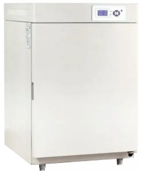
CO2 Incubator Air Jacketed BCAJ-8401
- With Infrared CO2 Sensor
- • Faster CO2 concentration Restoration Speed.
- • Infrared sensor can keep CO2 concentration stability and uniformity when door open frequently.
- • Polished stainless-steel chamber, semicircular arcs at corners for easy cleaning(except
- water-jacketed type), and the space between the shelves in the chamber is adjustable.
- • Microorganism filter at inlet provides 99.99% filtration of bacteria and dust (Φ<0.3μm)
- and supplies pure CO2 into the incubator.
- • Door temperature controller prevents dewfall on glass door of incubator effectively.
- Up to 3-Year Product Warranty
- US & EU Compliance Standards
- Door-to-Door Shipping
Technical Specifications
Detailed operating and construction parameters for this model.
| Model | BCAJ-8401 |
| Electrical Requirement | 220V 50Hz |
| Power Consumption | 450W |
| Heating Method | Air-jacketed, PID Control |
| Temperature Range | RT+5~55°C |
| Ambient Temperature | +5~30°C |
| Temperature Stability | ±0.2°C |
| CO₂ Range | 0~20% V/V |
| CO₂ Control Resolution | ±0.1%(IR sensor) |
| CO₂ Recovery | (Door open 30s, recovery to 5%) ≤ 3min |
| Temperature Recovery | (Door open 30s, recovery to 37°C) ≤ 8min |
| Humidity Method | Natural vaporization ≥ 90% |
| Chamber Volume | 50L |
| Interior Dimension (WxDxH)mm | 400x285x350 |
| Exterior Dimension (WxDxH)mm | 580x450x730 |
| Shelves | 2(pcs) |
| Sterilization Method | UV Sterilizer |
| Packing Dimension | - |
| CBM | - |
| Net Weight | - |
| Gross weight | - |
Product Features
Key design, performance, usability, and safety advantages.
Operating Manual View instructions, operating procedures, safety information, and maintenance guidance.
1. Instruction for Safety
2. Product Profile
2.1 Outlook
2.2 Overview of Structure and Function
3. Use of Product
3.1.Conditions for Normal Use
3.2.Major Technical Indicators
3.3. Layout of Operating Panel
3.4. Usage
4. Instructions for Use of Product
5.Appendix
1. Instruction for Safety
1. The Product must be safely grounded and kept away from electromagnetic interference sources (make sure not to use the ZL or neutral line as the earth wire).
2. Before use, make sure that the power supply has the voltage in compliance with the requirement of the Product.
3. For the Product, a separate power socket should be used and make sure the plug and socket is properly grounded.
4. With the production running, it is not allowed to pull out and plug in the power plug at random without turning off the power switch.
5. Random extension or cutting of the product's power cable is prohibited.
6. Unauthorized repair is not allowed and such authorized repair should be carried out by the special personage.
7. The steel cylinder for carbon dioxide arranged by the user is a pressure vessel, which shall comply with the national codes for management of pressure vessels.
! Warning (possible to cause losses to properties or injuries to personages)
1. Make sure to read and understand thoroughly the Product's Operating Instructions before the operation may be carried out.
2. To take out the power plug, make sure not to pull the power cable.
3. In case of any one of the following circumstances, make sure to take out the product's power plug:
3.1 To change the fuse tube.
3.2 Pending for checking and repair in case of any breakdown with the product.
3.3 The product will not be used for a long period of time.
3.4 To shift the product.
! Caution (it may influence the lifetime cause the abnormal operation of the product)
1. In handling the product, be cautious not to damage such fragile parts as instruments on the panel.
2. The product should be located on the solid and hard surface to keep it in a horizontal mode.
3. Keep certain space around the product.
4. The product must be used in the specified conditions.
5. Each time after the product is used for experiment, water content shall be dried out from the inner chamber to avoid any rust and corrosion that may affect the lifetime.
6. The product should be placed on the bench, with the case stand firmly fixed to avoid any movement that may damage the product and cause human injury.
7. Avoid opening or closing the box door heavily, otherwise doing so will cause the falling of the box door, damage to the product and injury accident.
8. With the product stored for a long period of time, regular heating shall be applied to eliminate humidity and avoid any damage to the parts.
2. Product Profile
2.1 Outlook
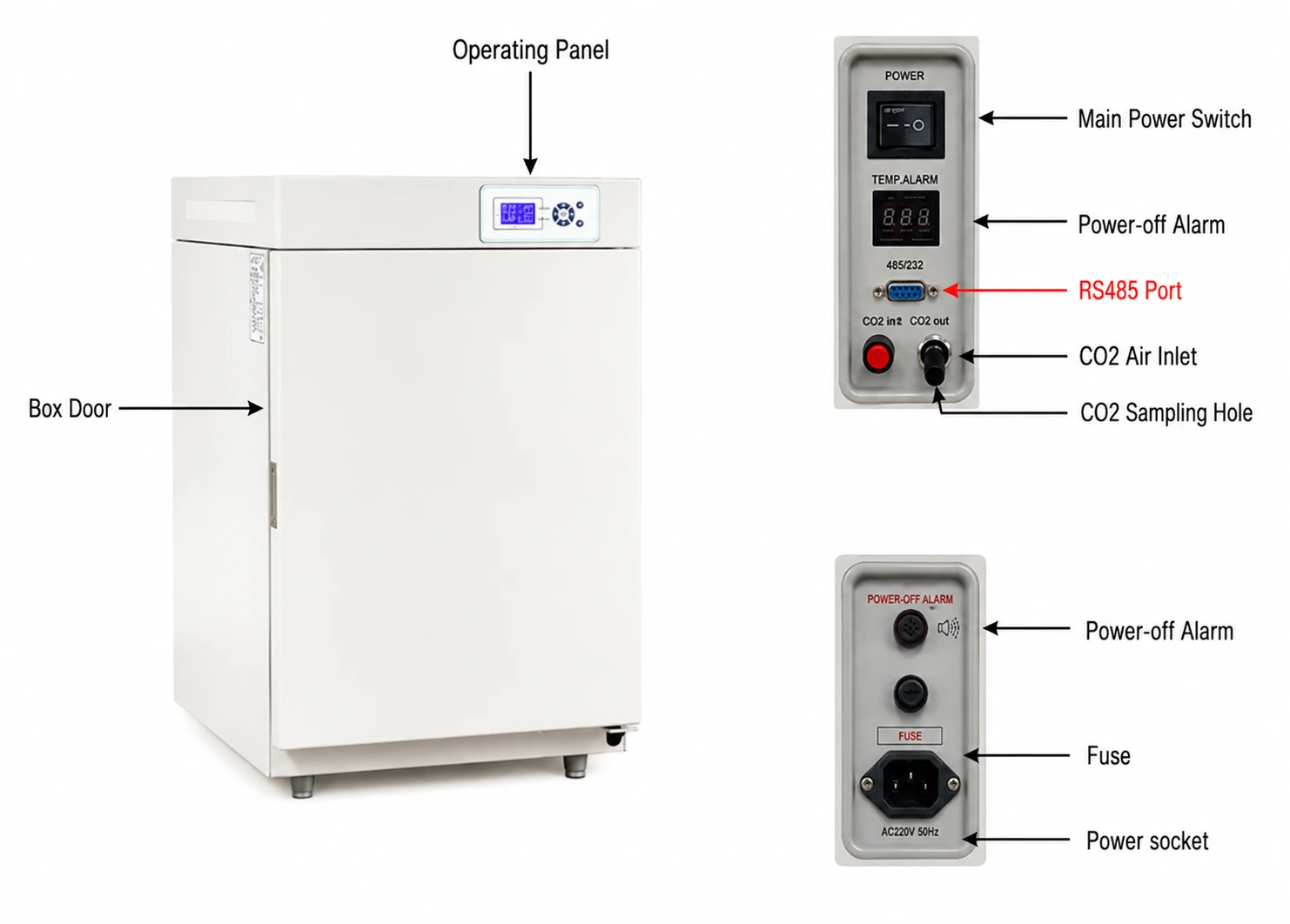
Figure 1
2.2 Overview of Structure and Function
CO2 Box is an air-case CO2 incubator fabricated according to the air-distributing principle and is composed of a case, inner chamber (working chamber), temperature and CO2 density control device and gas cycling device.
It shall be used with CO2 steel cylinder and CO2 relief valve. (CO2 gas shall have a purity of over 99.0% and the relief valve shall be stable. CO2 steel cylinder is a pressure vessel to be provided by the user, while the special CO2 relief valve shall be provided by the Company along with the product).
1) The case is of a desk-top frame construction, with the surface plasticized for bright color and nice appearance.
2) The chamber made of mirror-face stainless steel sheet. The case and chamber is filled with insulating materials to increase the thermal insulation performance.
3) The thermal controller uses the micro computer, with the feature of PID adjustment and such functions as temperature failure alarming, etc. With Pt100 platinum resister used as the sensor, the control accuracy and reliability have both been massively improved.
4) Automatic control of CO2 density: air and CO2 is input into the chamber by proportion and will be constantly replenished after the density value is reached so that the CO2 density in the chamber will be kept stable. Additionally, upon opening and closing the door, the CO2 density in the chamber will be restored within a certain period of time.
5) The gas enters the case through the filter (0.3u) to keep the purity of CO2 gas.
6) In case of any requirement for humidity, it will be resolved by means of natural evaporation. One water pot is placed in the chamber and by changing the evaporation area of the pot, the humidity in the case will change and can reach about 95%RH to the maximum. (The product is not equipped with the function of humidity display and control)
7) Double-door structure is adopted. The case door is of the heating function; with the door temperature at 37°C, the set temperature is slightly higher than the case temperature to ensure the observation of products through the inner glass door. Addition, one door control switch is installed at the left upper corner of the case behind the glass door. With the glass door opened, the fan in the heating and gas cycling device will be automatically off so as to prevent the temperature and CO2 density from being out of control.
8) Magnetic gasket issued for the case door and silicon rubber sealing strips are used for the inner glass door and the case to ensure the sealability of the product.
9) For the convenience of the user, one CO2 sampling and monitoring port is set on the right of the CO2 case (see Figure 1), which can be used to monitor the CO2 density in operation. When the relative humidity exceeds 70%, between CO2 sampling and monitoring port and the analyzer, it shall be necessary to insert the "dehumidifier" for ensuring the measurement accuracy.
10) The Product is of the function for heat disinfection: microbe and fungal spore on the surface of the chamber can be effectively killed.
11) Power-off alarming function (optional): used to draw the attention of the operator in case of any sudden power-off during experiment.
12) RS485 function (optional): for operation, see the attached CD.
13) Auto gear of fan speed: sample evaporation due to excessive air flow can be avoided during the experiment.
3. Use of Product
3.1.Conditions for Normal Use
a) Ambient temperature: (5~30)°C.
b) Ambient relative humidity: <90%.
c) Atmospheric pressure: (86~106) kpa.
d) Without any strong vibration and corrosive gas nearby.
e) Avoid any direct sunlight or impact of other cooling and heating sources.
3.2.Major Technical Indicators
Model | BCAJ-8401 | BCAJ-8402 | BCAJ-8403 |
Power supply | AC (220±22)V (50±1)Hz | ||
Input power | 450 W | 500 W | 750 W |
Thermal control range | (RT+5°C)~55°C (RT-room temperature) | ||
Temperature fluctuation | ±0.2°C | ||
CO2 density control range | 0-20% V/V | ||
CO2 density recovery time | ≤ density value x1.2min | ||
CO2 density control error | ±0.3% | ||
Chamber size (W*D*H mm) | 400*340*400 | 400*400*500 | 530*480*610 |
Outer size (W*D*Hmm) | 580*450*540 | 590*657*870 | 670*740*980 |
Table 1
* 0.1°C-accuracy mercurial thermometer and RD-7AG CO2 analyzer are used for testing.
* The relevant data is measured and obtained with the ambient temperature of 25°C and relative humidity of less than 85%.
3.3. Layout of Operating Panel
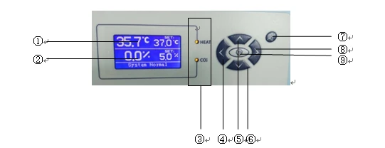
Figure 2
Notes for displayers
1.Temperature display (Unit: °C)
2.CO2 Display (Unit: %)
3.LED :HEAT -------Heating indicator. When PV (display) is close to SV (Setting), the led flickers, as is normal, indicating the state of proportional regulation.
CO2 indicator. ------- With the led on, it indicates air charging.
4.  The return key.
5.  Add key ------- Display value increases.
6.  The reduction of key ------- Display value to reduce.
7.  Mute button ------- When the alarm sound, according to the mute button alarm disappear.
8.  UV light button.
9. 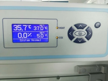 Each parameter adjustment must be confirmed by the key, otherwise the modification is invalid.
3.4. Usage
1) Install and connect CO2 Steel Cylinder
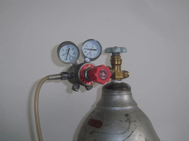
Figure 3
a) Install the enclosed relief valve on the CO2 Steel Cylinder, without any leakage at joint and turning on the steel cylinder.
b) With the silicon rubber tube (outer diameter of φ12 and inner diameter of φ8), connect the output joint of the relief valve with the air inlet on CO2 Box, fixing it firmly with the hold-down ring to avoid any air leakage. (Insert the auxiliary germ filter between the relief valve and the air intake tube of CO2 Box)
2) Cleaning and Sterilizing
With alcohol, clean the chamber of CO2 Box and apply the high-temperature sterilization by setting the instrument.
3) Power On
a) It is necessary to close properly the glass door and the case door; otherwise the alarming indicator will not be in a proper working state.
b) Unscrew the valve on the cylinder clockwise and open the CO2 cylinder so that the pressure gauge on the pressure reducing valve indicates that the CO2 gas pressure in the cylinder is about 5Mpa (the cylinder should be replaced when the cylinder pressure is lower than 1Mpa).
c) Set the total power switch (POWER) of the cabinet to the "I" position. At this time, the LED display will be on, showing the measured temperature and CO2 concentration, indicating that it is energized and enters the working state.
4) Method for Parameter Setting and Adjustment
A) Temperature setting and CO2 setting change
Press the  button, the window displays "Temp set", press the key or
  key, so that the window shows the required set temperature (ie SV value), then press the key
  to confirm.
Press the button, the window shows "CO2 set", press the key or key, so that the window shows the required CO2 concentration, then press the key to confirm.
Press the  button, the window displays "UV CT1", press the key or
  key to switch the UV lamp status. "ON" is on, "OFF" is off; then press key to confirm.
Note: After each parameter has been adjusted, press the modified value.
B) Temperature alarm and concentration alarm settings
Press the button, the cursor shows "ALM TEMP", then press the button, the flashing state keys or keys to rewrite the temperature alarm value.
Press the button, then press the button, the cursor moved to "ALM CO2", then press the button, flashing state keys or keys to rewrite the CO2 alarm value.
Note: After each parameter has been adjusted, press key the modified value is stored.
C) List of Parameters
Character | Parameter name | Description | Range | Ex. Factory Value |
ALM TEMP | Temperature deviation alarm | When the display temperature ≥ S2 + AL, the display shows "Temp High Alarm", the buzzer alarm and cut off the heating output. | -10~10 °C | |
ALM CO2 | Concentration deviation alarm | When the display concentration ≥ SV + AL, the display shows "Co2 High Alarm", the buzzer alarm and cut off the CO2 output. | -2.0~2.0% |
Table 2
4. Instructions for Use of Product
1.The unit shall be installed in a room with clean air, without any direct sunlight, strong electromagnetic field and quantity of radiant energy and with limited change of ambient temperature. In order to ensure the control accuracy of the CO2 box, it is recommended for use in an environment of 15°C~25°C.
2.Before turning the unit, read carefully the operating instructions and understand accurately the usage. Especially, make sure to screw, before turning on the steel cylinder, tightly the relief valve to avoid the burst of air intake rubber tube.
3.When the difference between the ambient temperature and the set temperature is less than 5°C, air conditioning shall be applied to reduce the ambient temperature to ensure the control accuracy. In the whole process of incubation, it is necessary to keep the ambient temperature stable; otherwise, the accurate control of temperature in the CO2 Box may be affected.
4.When the condensation on the door close affects observed, it is necessary to adjust appropriately the heating capacity of the door up to elimination of such condensation, but the heating capacity of the door may cause massively the unstable case temperature or steady-state error.
5.It is recommended to change, at random, the parameters with ※ in the menu since it may affect the normal operation of the CO2.
6.When the pressure of the steel cylinder is less than 1Mpa, change it timely. To replace a steel cylinder, it is necessary to first turn off its valve, unscrew the shaft of the relief valve and remove and install it on the full steel cylinder.
7.When the unit is used for the first time or after be stored for a long time, it is necessary to follow the requirements described in Paragraphs 1)~3) of 4. Usage, Chapter IV. Especially in the process of formal incubation, it is necessary to carry out the non-pollution checking (for details, see Appendix 1).
8.CO2 Box shall be equipped with a proper grounding device to ensure safety.
5.Appendix
Appendix 1
Pollution Inspection Method
Two incubation dishes with cultures shall be used. One will be artificially polluted: for instance, breathe on the dish surface and cover it before being placed into the box for incubation. The other dish shall not be polluted and cover halfway before being placed into the box for incubation. If the polluted one has mixed bacterium, while the other one has not, it proves that the box has been sterilized and clean inside.
Appendix 2
Troubleshooting
Sr. No. | Description of Breakdown | Assumption of Reasons | Method for Troubleshooting |
1 | No power supply upon start-off | There is no electricity at the power socket | Check the power socket and repair |
CO2 box's power cable is not properly connected | Repair and check power cable and connector | ||
Main power switch is off or out of order | Turn the power switch to the position of "I" or replace | ||
Fuse is burnt out | If it burns out again after replacement, it is necessary to check if the CO2 box has any part out of order and change | ||
2 | No heating | Door switch is out of order | Door switch is not connected or out of order, adjust the door holder space; close the glass door tightly |
Control meter is out of order | Adjust the control panel | ||
Heating film is open or connector is loose | Replace and repair | ||
3 | Inaccurate temperature or overshoot or heating | Fan does not work | Replace the fan |
Pt100 is in poor contact | Check the Pt100 connection and replace | ||
Parameters of PK, P, Ar, etc are properly set | Reset | ||
4 | Temperature out of control | Ambient temperature is excess high and its difference with the set temperature is <5°C | Turn on air conditioning to improve RT (room temperature) |
5 | Temp displaces "OOO" | Sensor fails or input signal is beyond the measurement scope | Repair the sensor or check if the temperature is too high inside the case |
6 | CO2 density fails to increase | CO2 steel cylinder is not open and gas duct is choked | Open the valve on the steel cylinder |
Output pressure of CO2 steel cylinder is excess low or the filter bursts or duct is choked or leaks | Change the steel cylinder, rubber tube and adjust the filter | ||
Air inlet valve out of order | Replace | ||
7 | CO2 Box leaks | All joints | Repair |
Fan axle leaks or door seal leaks or filter leaks | Change the axle seal or use silicon rubber fill up the leakage, change the door sealing strip | ||
8 | CO2 density shows a major deviation | Parameter is not properly set | Reset |
Output of pressure meter is incorrect | Reset |
Table 3
Appendix 3
Illustrative Diagram for Circuit Connection
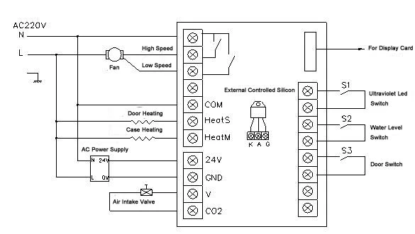
Figure 4 (Air-casing CO2 Incubator)
Appendix 4
Packing List
Sr. No. | Type | Description | Unit | Qty | Remarks |
1 | Doc | Operating Instructions | Copy | 1 | |
2 | Doc | Packing List | Copy | 1 | |
3 | Accessory | Fuse core | Pc | 2 | |
4 | Spare Part | Shelf | Pc | 80CH:2 150CH:3 | |
5 | Spare Part | Filter | Pc | 1 | |
6 | Spare Part | Relief valve | Pc | 1 | Optional |
7 | Spare Part | Air inlet rubber tube | Pc | 1 | |
8 | Spare Part | Power cable | Pc | 1 | |
9 | Spare Part | Water pot | Pc | 1 |
Table 4
The articles listed above are physically in compliance with the items packed.