
Get Price
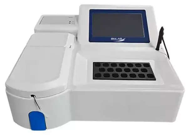
Auto Chemistry Analyzer BANA-806
A semi-automatic biochemistry analyzer is a microcomputer-based in-vitro diagnostics instrument uniting optics, mechanics, and automation control in one. It is used together with the related reagents for the quantitative determination of biochemical items, widely applied to various hospitals and research institutes, with the characteristics of high...
- 1. 7.0 inch LCD touch screen, graphical interface is easy to use.
- 2. Large memory space, can store 300 test items, 20, 000 test results.
- 3. Built-in thermal printer to print measurement results and flag abnormal results.
- 4. Incubator intelligent temperature control, room temperature, 25.0°C, 30.0°C, 37.0°C four temperature options.
- Up to 3-Year Product Warranty
- US & EU Compliance Standards
- Door-to-Door Shipping
Technical Specifications
Detailed operating and construction parameters for this model.
| Model | BANA-806 |
| Sample Type | Serum, Plasma, Urine, Cerebrospinal fluid, etc |
| Analytical Method | End point method, Fixed time method(two-point method), Dynamic method(rate method) |
| Incubating Positions | 20 incubating positions |
| Incubator Temperature | R.T. 25°C, 30°C, 37°C, four temperature options |
| Cuvette | Flow through a direct-reading cuvette |
| Wavelength | Wavelength 340/405/450/510/546/578/630nm, 2 more open filter positions |
| Wavelength Accuracy | ±2nm |
| Screen | 7.0 inch LCD touch screen |
| Language | English, French, Spanish, other languages can be customized |
| Printer | Built-in thermal printer |
| Interface | RS-232, USB |
| Consumption | 150VA |
| Power Supply | AC110/220V±10%, 60/50Hz |
| External Size(W*D*H) | 400*410*190mm |
| Packing Size(W*D*H) | 520*490*330mm |
| Net Weight | 9kg |
| Gross Weight | 12kg |
Product Features
Key design, performance, usability, and safety advantages.
Operating Manual View instructions, operating procedures, safety information, and maintenance guidance.
1. Safety Symbol
2. Main Introduction
2.1 Configuration and Structure
2.2 Main Technical Parameters
3. Installation
3.1 Requirement of Installation
3.2 Unpacking
3.3 Installation Steps
3.4 Installation and Use of Semi-automatic Data Management Software
4. Main Menu Functions
4.1 Working Principle
4.2 Introduction of Main Menu Functions
5. Operations
5.1 Parameter Setting
5.2 Daily Operation Process
1. Safety Symbol
Various safety symbols are used in this user manual and the analyzer to remind you of taking care. As shown in the following table :
Symbol | Implication | Description |
| Caution | When seeing this mark, it is necessary to consult the user manual to ascertain the nature of the potential hazard and any action that must be taken. Do not open the cover or touch the parts near the warning mark when the device is running. If you do not follow the instructions in the user manual to use the device, the protective measures provided by the device may fail. |
| Biological infection risk | Used for reagent&sample probes and waste drains. Indicate a risk of biological infection, and if not followed, there may be a risk of biological infection. |
| Protective conductor terminal | For internal and external grounding. Please ensure that the instrument is well grounded. |
| Manufacturer | On the nameplate. Indicates manufacturer information. |
| Operator's manual | Identify the location where the operator's manual is stored or information that relates to the operating instructions.Indicate that the operating instructions should be considered when operating the device or control close to where the symbol is placed. |
| In vitro diagnostic instrument | On the nameplate position. Indicates that the medical instrument is an in vitro diagnostic medical instrument. |
| European Authorized Representative | On the nameplate. Represents the authorized representative of the European Union. |
| CE mark | On the nameplate. Indicate that this medical device has been assigned to class A according to Annex II + Annex III + Article 17 of IVDR (EU) 2017/746. |
| This way up | Indicate correct upright position of the transport package. |
| Fragile | Contents of the transport package are fragile therefore it should be handled with care. |
| Keep away from rain | Transport package should be kept away from rain. |
| Do not roll | Transport package should not be rolled. |
| Do not stack | Stacking of the transport package is not allowed and nothing can be placed on the transport package. |









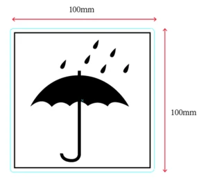


Table 1
2. Main Introduction
Semi-auto Chemistry Analyzer is a microcomputer-based in-vitro diagnostics instrument that gathers optics, mechanics and automation control. It is used together with the related reagents for quantitative determination of biochemical items, widely applied to hospitals and research institutes, with the characteristics of high precision, excellent repeatability, with LIS software, etc.
2.1 Configuration and Structure
It mainly consists of control system, incubation system, optical and measuring system, peristaltic pump suction system, built-in thermal printer, etc.
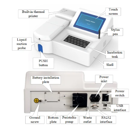
Figure 1
2.2 Main Technical Parameters
Technical parameter | Standard specifications | ||
Cuvette | Type of cuvette | Flow through direct-reading cuvette | |
Incubator | Incubator position | 20 pcs | |
Temperature control | R.T., 25.0°C, 30.0°C, 37.0°C | ||
Accuracy of temp control | ± 1°C | ||
Temperature fluctuation | ± 0.4°C | ||
Photometric System | Light source | 6V, 10W halogen lamp | |
Wavelength of transmitted light | 340/405/450/510/546/578/630nm wavelength, with two expandable positions | ||
Accuracy of wavelength | ±2 nm | ||
Measuring System | Measuring range | 0~3.500 OD | |
Linear range | ±2% from 0 to 2.500 OD | ||
Aspiration accuracy | ±0.02 OD | ||
Zero drift | Less than 0.005 OD | ||
Accuracy of linear aspiration | 0.2~0.5 OD | ±5% | |
0.5~1.0 OD | ±4% | ||
1.0~1.8 OD | ±2% | ||
Repeatability of aspiration | Coefficient variance(CV) ≤1.0% | ||
Analysis method | End point method, fixed time method (two-point method), kinetic method (rate method), etc. | ||
Instrument | Type of display | Touch screen | |
Type of printer | Built-in thermal printer | ||
Interface | RS-232, USB | ||
Machine weight | 9kg | ||
Gross weight | 12kg | ||
External size (W*D*H) | 400mm*410mm*190 mm | ||
Package size (W*D*H) | 520mm*490mm*330 mm | ||
Installation and storage | Power supply | AC100-240V, 50Hz/60Hz | |
Storage and usage requirements | Storage: -10°C ~ 40°C, < 85%RH, Working: 15°C ~ 30°C, 40%RH ~ 85%RH, Altitude: Below 2000m | ||
Table 2
3. Installation
The installation and operation of this instrument is simple and easy to operate. In principle, no engineer is sent to install. Before leaving the factory, commissioning and calibration by professionals, after the customer receives the instrument, install it according to the requirements of this chapter.
Attention :
Violation of the installation in this chapter may cause problems or damage the instrument. Such problems or damages are not covered by the free warranty.
3.1 Requirement of Installation
Before the installation, the user and engineer must check and confirm that the lab meets the requirements of space, power supply and working environment, etc.
3.1.1 Space requirements
To ensure enough space for releasing heat, repairing, maintenance, keeping the pipeline not squeezed and ensure the fluid can flow freely, the space must meet the requirements as follows:
• Keep the analyzer at less than 100mm distance from the wall and other objects for each side (left, right and back).
• Provide enough space close to the instrument to place containers of pure water and waste.
3.1.2 Power requirements
Power supply: AC100-240V, 50Hz/60Hz.
Power socket: A well-grounded socket within one meter of the instrument.
Attention :
• The power supply socket should be within 1m from the analyzer in order to disconnect the plug timely when an accident happens.
• Check if network voltage is the same with the analyzer voltage.
3.1.3 Environmental requirements
• Working temperature: 15°C ~ 30°C
• Working humidity: 40% ~ 85%
• Working atmospheric pressure: 86.0kPa ~ 106.0kPa
• Fuse: F3AL250V(5*20mm)
• Input power: 150VA
• The environment should be in a quiet and clean room and keep away from dust, noise, big equipment (X-ray machine, CT, centrifuge, etc) and radio interference.
• Avoid direct sunlight and ultraviolet rays and keep away from hot and cool sources and outlets of air conditioning.
3.1.4 Computer configuration requirement
The semi-auto chemistry analyzer is equipped with a semi-automatic data management software, which is convenient for users to transfer data to the LIS system. Users need to contact our customer service center to obtain this semi-automatic data management software and install it on a computer that meets the following requirements.
Computer host configuration requirements:
• It must be a branded machine with a CPU frequency of ≥2.8GHz or above, a hard disk of 80G or above, a partition ≥2 (C, D...), a memory ≥2GB, and a stable USB interface.
• Install Windows 7 and above operating system, 32-bit or 64-bit version, Microsoft.NET Framework 4.0 and semi-automatic data management software, and Microsoft Office Access software is recommended to install.
The display configuration requirements:
• 17 inches or more, the resolution is not less than 1366*768.
3.2 Unpacking
3.2.1 Unpacking steps
After the analyzer arrives, please carefully check the package to see if there is any damage, such as broken, wet or polluted. If there is, please contact our company.
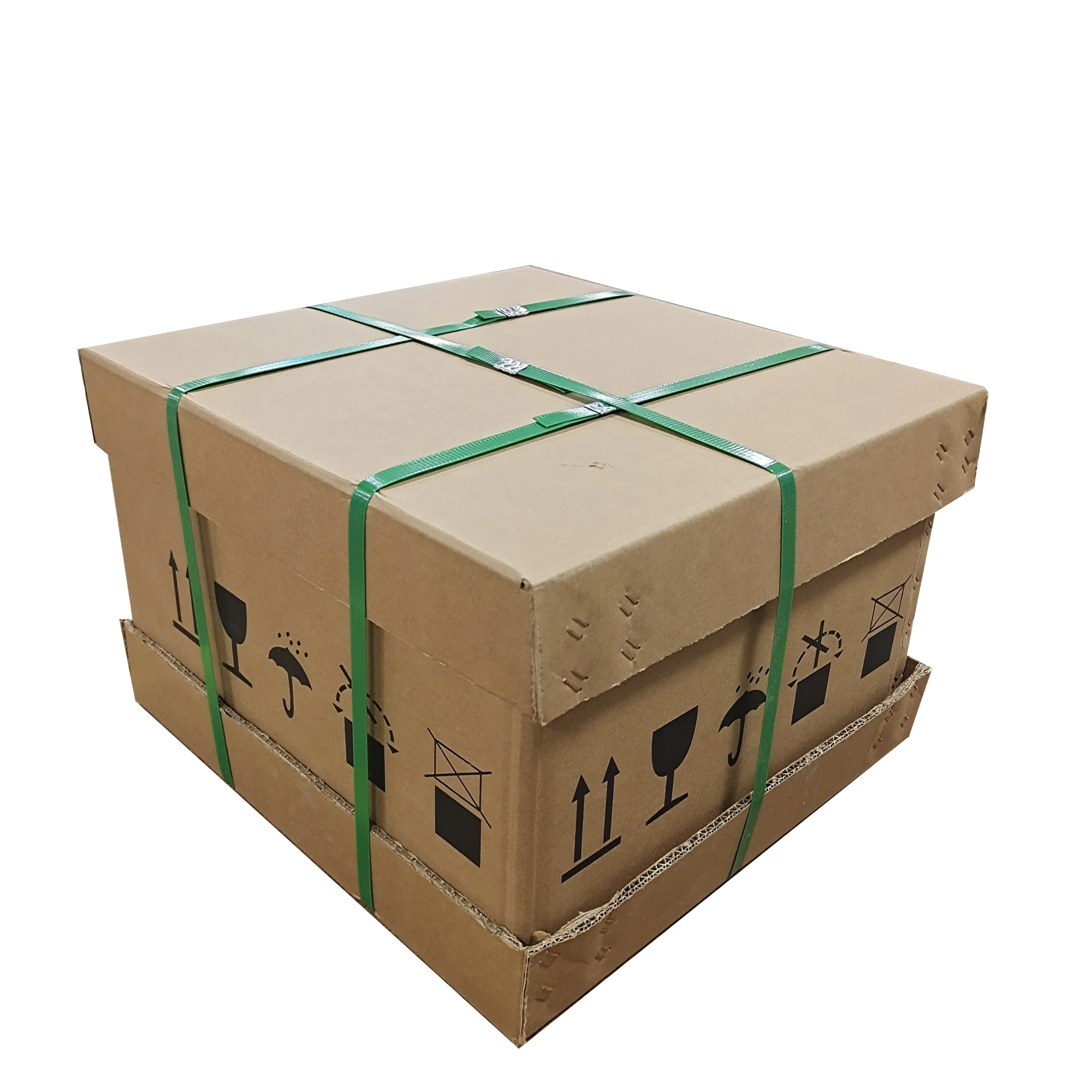
Figure 2
After confirming that there is no external damage, open it by following steps:
• Open the box and according to the accessories list to check whether the object is complete, if missing, please contact our company.

Figure 3
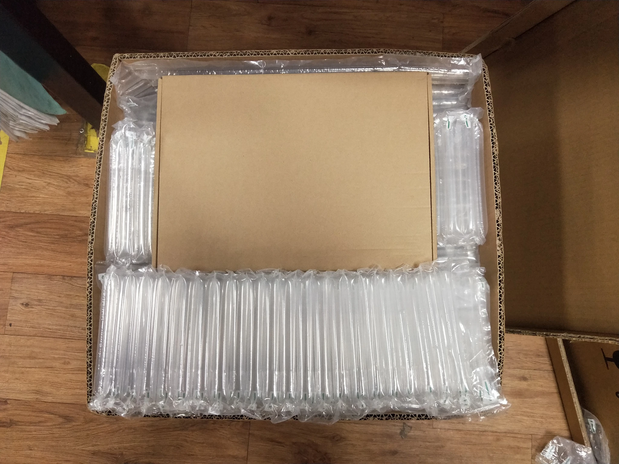
Figure 4
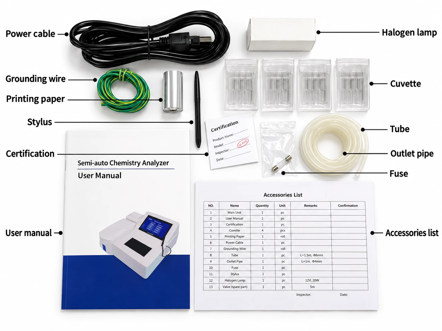
Figure 5
• Carefully check the appearance of the instrument, if damaged, please contact our company timely.
• Check whether the ex-factory number or serial number is in accord with the package.
• As shown in figure below, open the operation window and pull out and adjust the suction probe.
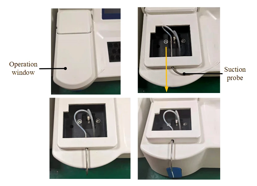
Figure 6
3.3 Installation Steps
1. Place the instrument on a stable worktable.
2. Take out the power cable and outlet pipe from the accessory box, connect the power cable to the designated power supply according to the following figure, plug one end of the outlet pipe into the out joint and plug another end into the waste container. The instrument connects to a computer with a serial cable to use the LIS function. (Contact our customer service center for details.)
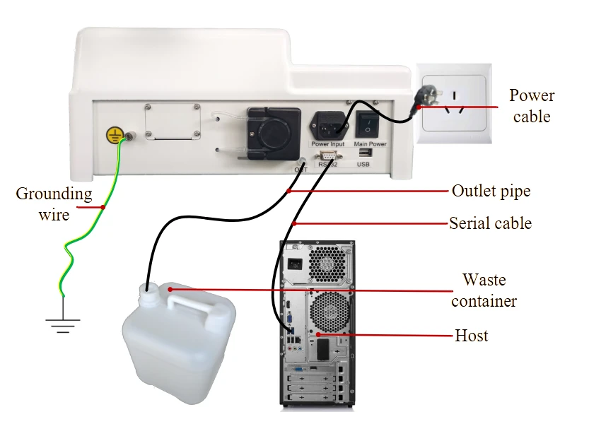
Figure 7
3. Switch on the main power before testing. ("|"means connected, "O" means disconnected.)
4. Install the thermal printing paper shown like below :
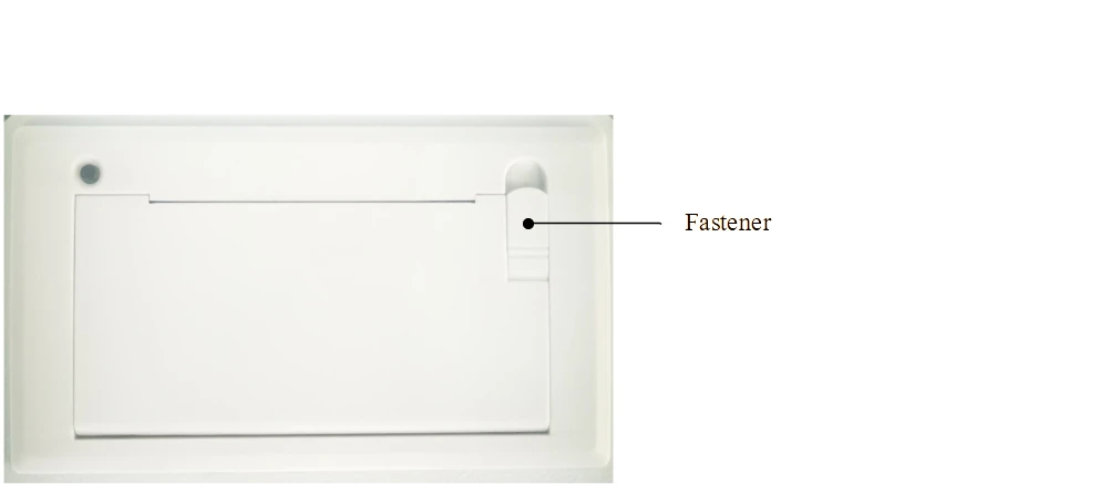
Figure 8
Open the printer cover by turning up the "Fastener" in the upper right corner of the printer.
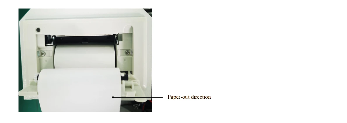
Figure 9
Load the printer paper into the paper slot and pay attention to the installation direction of the printer paper.

Figure 10
Put the paper to the feeding form and close the cover.
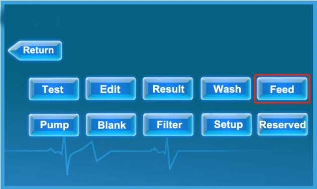
Figure 11
• Click [Feed] on the main menu, make sure the paper is running properly.
 Attention :
• When installing the thermal printing paper, pay attention to the direction of the paper.
• Before installing the printing paper, do not print, or else it would result in a system crash.
• The suction probe or waste fluid joint may carry some serum, reference substance, calibrator or reagent, which is of potential biological risk. Therefore, do not touch the probe directly with your hands to avoid danger.
3.4 Installation and Use of Semi-automatic Data Management Software
Contact our customer service center to obtain [Semi-automatic data management software].
[Semi-automatic data management software] can obtain the internal data of the instrument online, can edit the sample information and bind with the test results, can view and print the test items and results of the sample.
Note:
The semi-automatic data management software must be installed before using the LIS function.
3.4.1 Installation
Contact our customer service center to get the software, and double-click "Semi Automatic.exe" to complete the installation.
3.4.2 Confirm the port number
Right-click on [My Computer]-[Computer Management]-[Device Manager] to view the COM number of the serial cable connected to the instrument (note: if the port is not found in the device manager, just plug and unplug the serial cable again).
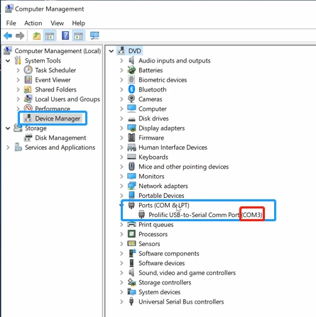
Figure 12
3.4.3 Go online and get data
After opening the LIS software, select the port number and click [Open] which then would show "Open successfully!", which means the connection is successful.
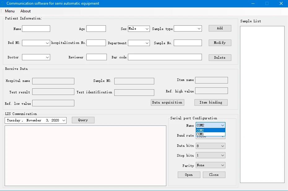
Figure 13
After the connection is successful, click [Data acquisition] to obtain the internal database of the instrument.
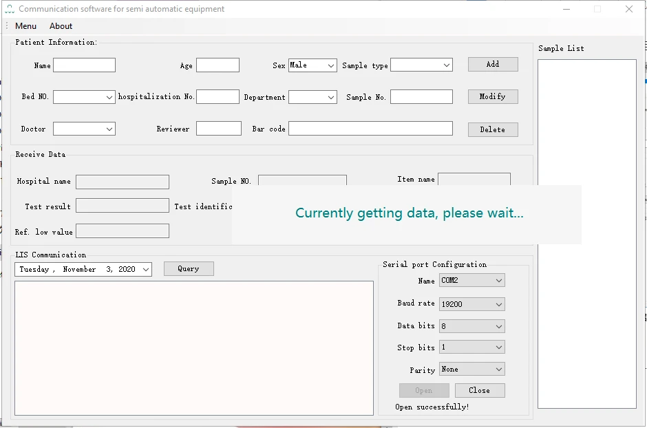
Figure 14
After selecting the test date and clicking [Query], all test results of the day would be automatically filtered out.
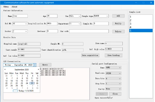
Figure 15
Click [Add] to automatically generate a sample number, enter patient information on the left, and click [Save] to save the sample information.
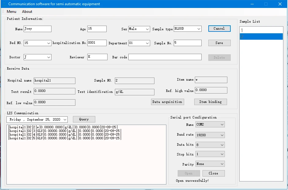
Figure 16
After selecting a sample, click to select the test result, and click [Item binding] to bind the test result to the sample information, as shown in the figure below, displaying "Successfully added item for sample!" which means that the test result is successfully bound.
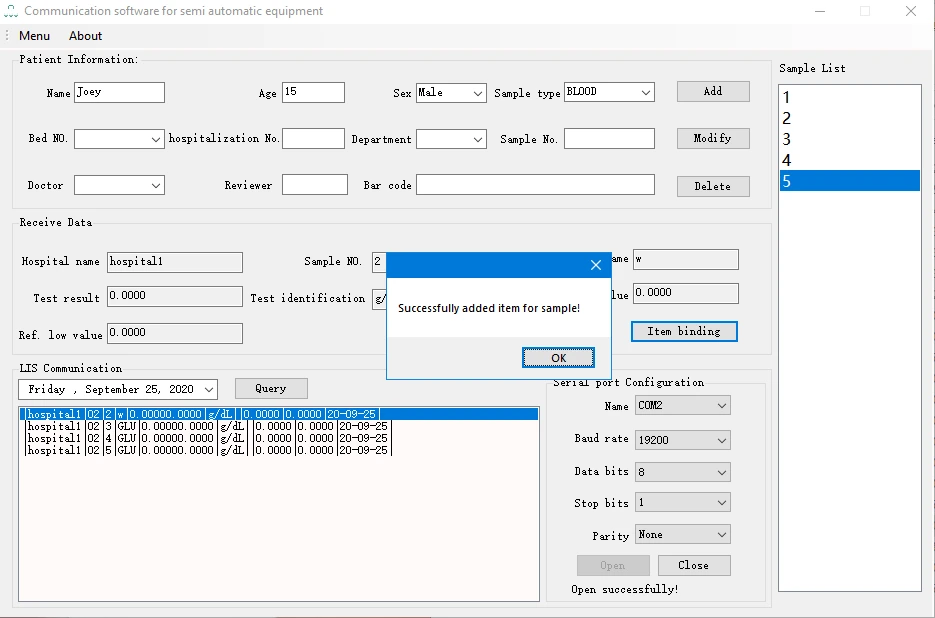
Figure 17
In the [Sample List] column, double-click a group of samples to pop up all the test items and results of the sample, click [Preview] to preview the report printing results, and click [Print] to print the report of the group of samples.
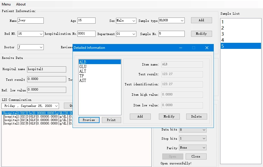
Figure 18
4. Main Menu Functions
4.1 Working Principle
The principle of analyzer is based on Lambert-Beer Law.
4.2 Introduction of Main Menu Functions
Turn on the instrument, the interface looks like the left figure. Click on the screen, it would enter function menu as shown in the right figure:
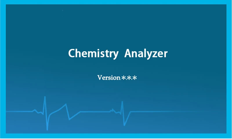
Figure 19
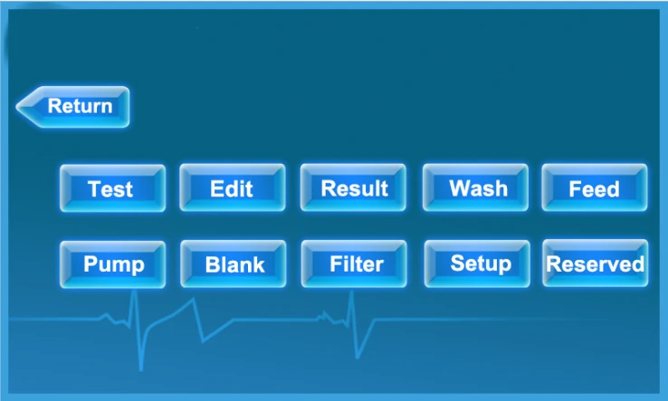
Figure 20
The menu functions are shown in the table. Touch screen to select the functions you need and enter the sub-menu.
No. | Menu name | Function | Operation |
1 | Test | Select the program to do sample test, after testing, the instrument would show the test results and print it automatically. | See 5.2.3 |
2 | Edit | Add, modify, delete or print test programs. | See 5.1.6 |
3 | Result | View, delete and print the sample and QC test results. | See 5.2.4 |
4 | Wash | The shortcut key for cleaning, aspiration volume is 1.5ml per keystroke, used to clean cuvette. | See 5.2.2 |
5 | Feed | The printer automatically feeds and prints a blank piece of paper. | See 6.3.2 |
6 | Pump | Calibration for Peristaltic pump aspiration volume. | See 5.1.5 |
7 | Blank | AD check to confirm whether the instrument is in the regular test status. | See 5.1.4 |
8 | Filter | Measure and adjust each filter's AD value, blank value and absorbance. | See 5.1.3 |
9 | Setup | Display temperature of cuvette and incubator, print settings, standby settings, screen brightness settings, time format and date/time settings, hospital settings, view version information, etc. | See 5.1.1 |
10 | Reserved | Contains settings for temperature calibration, aspirate format, plate calibration, etc. | See 4.1.2 |
Table 3
5. Operations
5.1 Parameter Setting
Proper parameter setting is the basic step before the daily testing. Only when the parameters are correct and reasonable can the instrument get accurate results. Parameter setting is mainly used to set parameters of temperature, aspiration, filter, program and other system parameters.
5.1.1 System settings
Click [Setup] on the main menu to enter the sub-menu [System Setup].
![5.1.1 System settings, Click [Setup] on the main menu to enter the sub-menu [System Setup]., Figure 21 BANA-806](https://biolabscientific.com/content/manual/20260922002/5.1.1-System-settings-i36-Biolab.webp "5.1.1 System settings")
Figure 21
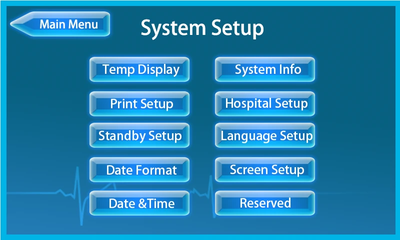
Figure 22
The user can click the key shown above to enter the sub-menu for checking or setting corresponding system parameters. After changing the parameters, click [System Setup] for return, pop up the interface shows like that, click [YES] to save changes.
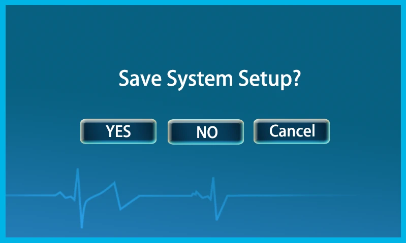
Figure 23
1. Temperature display
Click [Temp Display] on the [System Setup] menu to enter the interface as shown below. The interface displays the preset and real-time temperature of the cuvette and incubator measured by thermal sensor. The cuvette can be preset to four temperature levels. Note that when the room temperature is higher than the preset temperature, the temperature preset function would be invalid. Please adjust the room temperature first.
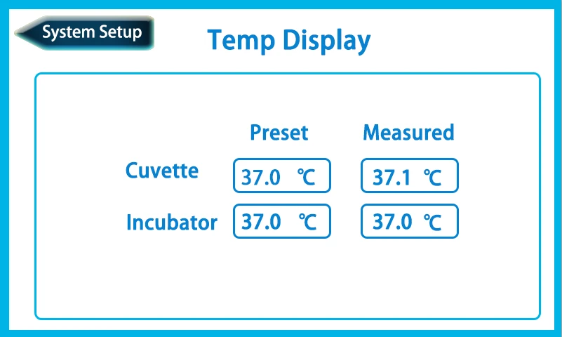
Figure 24
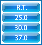
Figure 25
2. Print setup
Click [Print Setup] on the [System Setup] menu to enter the interface as shown below. The user can choose the print mode and whether to print the result or curve.
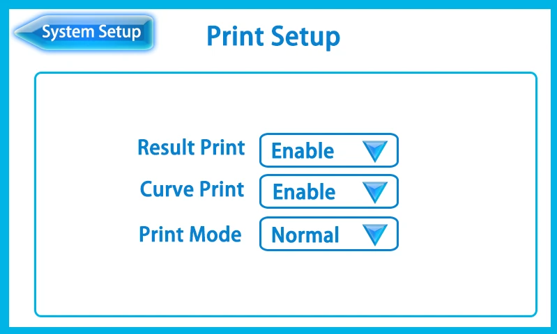
Figure 26
[Result Print]: Click ![[Result Print]: Click , choose [Enable] or [Disable] to decide whether to print the test result. If choose [Enable],](https://biolabscientific.com/content/manual/20260922002/Result-Print-Click-i42-Biolab.webp "[Result Print]: Click") , choose [Enable] or [Disable] to decide whether to print the test result. If choose [Enable], printing function is turned on, and the test result would be automatically printed during the test. [Disable] indicates that the printing function is turned off. The instrument would prohibit automatic printing of test results during testing, but the test results can be manually printed in [Result] menu.
, choose [Enable] or [Disable] to decide whether to print the test result. If choose [Enable], printing function is turned on, and the test result would be automatically printed during the test. [Disable] indicates that the printing function is turned off. The instrument would prohibit automatic printing of test results during testing, but the test results can be manually printed in [Result] menu.
[Curve Print]: Click , choose [Enable] or [Disable] to decide whether to print the curve result.
[Print Mode]: Click , choose [Normal] or [Concise] to decide the print mode.
Normal mode means that during the test process, the instrument would print the test results and curves one by one. Take the end point method test as an example as shown in below:
• Printing of AD Auto Zero Test :
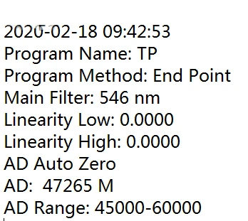
Figure 27
Printing of Blank Test :
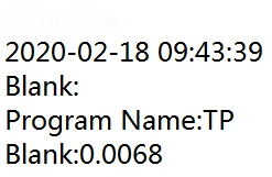
Figure 28
Printing of STD Test :
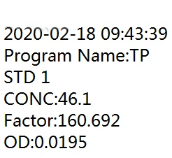
Figure 29
Printing of QC Test :
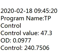
Figure 30
Printing of Sample Test :
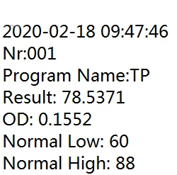
Figure 31
[Concise mode] means that to print the test results one by one in line with the principle of saving paper to make it easy to count, save and consult the results. Take the end point method test as an example as shown in below:
• Printing of AD Auto Zero Test:
![[Concise mode] means that to print the test results one by one in line with the principle of saving paper to make it easy to](https://biolabscientific.com/content/manual/20260922002/Concise-mode-means-that-to-print-the-test-results-one-by-one-in-i48-Biolab.webp "[Concise mode] means that to print the test results one by one in")
Figure 32
Printing of Blank Test:

Printing of STD Test:
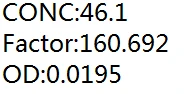
Figure 33
Printing of QC Test:
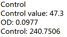
Figure 34
Printing of Sample Test:
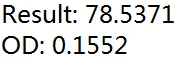
Figure 35
3. Standby setup
Click [Standby Setup] on the [System Setup] menu to enter the interface as shown below. Click the box after [Wait Time], pop up a soft keyboard for entering the wait time.
![3. Standby setup, Click [Standby Setup] on the [System Setup] menu to enter the interface as shown below. Click the box](https://biolabscientific.com/content/manual/20260922002/3.-Standby-setup-i53-Biolab.webp "3. Standby setup")
Figure 35
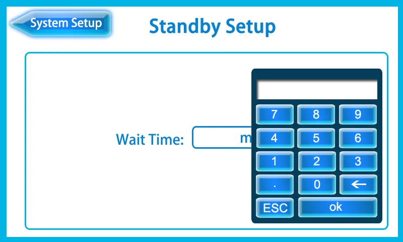
Figure 36
If the instrument has no operation in excess of wait time, it would enter the standby interface as shown below. Please touch the screen to wake up the instrument.
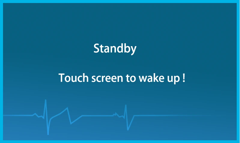
Figure 37
4. Date format
Click [Date Format] on the [System Setup] menu to enter the interface as shown below. Click , pop up a soft keyboard for changing the format of the date.
There are three date formats: YY-MM-DD, DD-MM-YY and MM-DD-YY. (YY represents year, MM represents month and DD represents day).
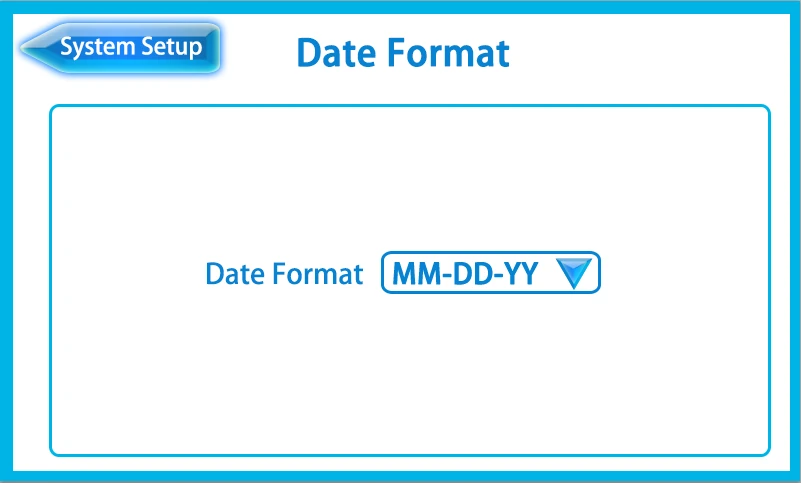
Figure 38
![Figure 39, Figure 4-7, 5. Date&Time, Click [Date&Time] on the [System Setup] to enter the interface as shown below., Click](https://biolabscientific.com/content/manual/20260922002/Figure-39-i57-Biolab.webp "Figure 39")
Figure 39
Figure 4-7
5. Date&Time
Click [Date&Time] on the [System Setup] to enter the interface as shown below.
Click the box after [Date] and pop up a soft keyboard for entering numbers. The date is entered in the order set in [Date Format].
The setting of time is the same as that of the date.
![Figure 39, Figure 4-7, 5. Date&Time, Click [Date&Time] on the [System Setup] to enter the interface as shown below., Click](https://biolabscientific.com/content/manual/20260922002/Figure-39-i58-Biolab.webp "Figure 39")
Figure 40
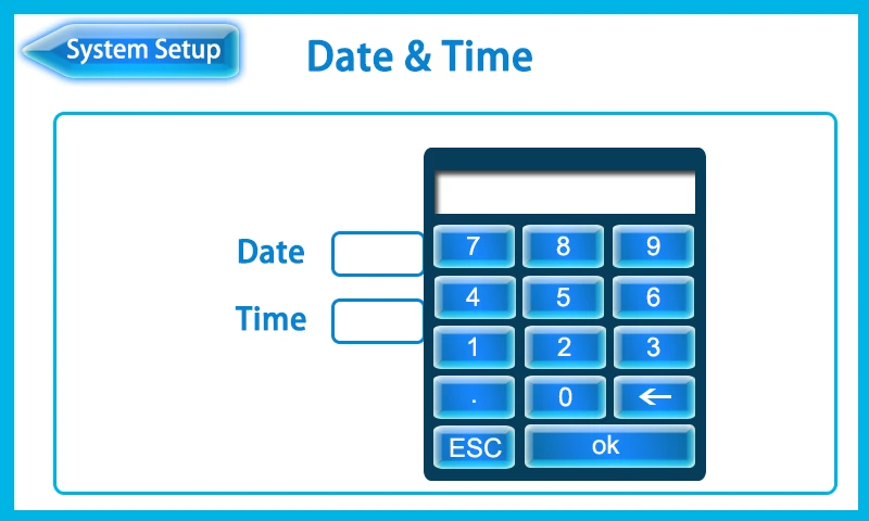
Figure 41
6. System info
Click [System Info] on the [System Setup] to check the system version.
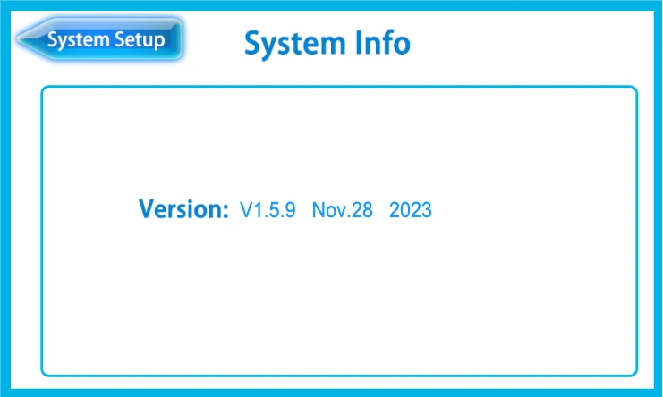
Figure 42
Figure 4-9
7. Hospital setup
Click [Hospital Setup] on the [System Setup] menu to enter the interface. Click the box, pop up a soft keyboard to input the hospital name.
![Figure 4-9, 7. Hospital setup, Click [Hospital Setup] on the [System Setup] menu to enter the interface. Click the box, pop](https://biolabscientific.com/content/manual/20260922002/Figure-4-9-i61-Biolab.webp "Figure 4-9")
Figure 43
8. Language setup
Click [Language Setup] on the [System Setup] interface to enter the following page, the default language is English.
![8. Language setup, Click [Language Setup] on the [System Setup] interface to enter the following page, the default language](https://biolabscientific.com/content/manual/20260922002/8.-Language-setup-i62-Biolab.webp "8. Language setup")
Figure 44
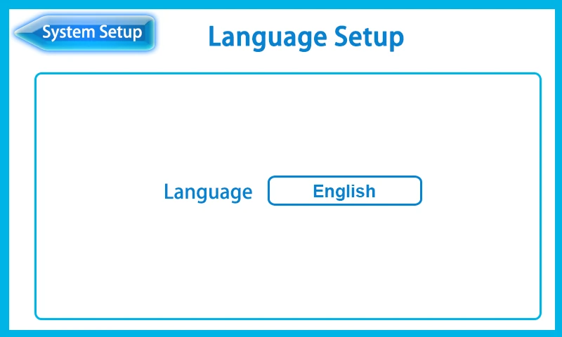
Figure 45
9. Screen setup
Click [Screen Setup] on the [System Setup] menu. Click or to adjust the screen brightness.
![9. Screen setup, Click [Screen Setup] on the [System Setup] menu. Click or to adjust the screen brightness., Figure 46](https://biolabscientific.com/content/manual/20260922002/9.-Screen-setup-i64-Biolab.webp "9. Screen setup")
Figure 46
4.1.2 Reserved settings
Click [Reserved] on the main menu, pop up a soft keyboard and then input the password "666666" to enter the sub-menu [Reserved Setting].
![4.1.2 Reserved settings, Click [Reserved] on the main menu, pop up a soft keyboard and then input the password "666666" to](https://biolabscientific.com/content/manual/20260922002/4.1.2-Reserved-settings-i65-Biolab.webp "4.1.2 Reserved settings")
Figure 47
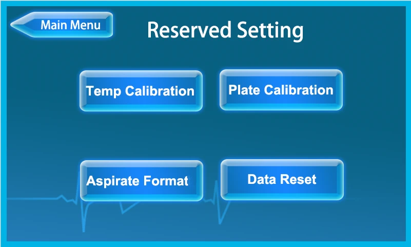
Figure 48
1. Temperature calibration
Temperature calibration includes the temperature calibration of cuvette and incubator. Click [Temp Calibration] to enter the interface as shown below.
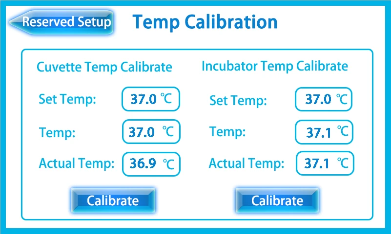
Figure 49
[Set Temp]: System preset temperature.
[Temp]: Display value of temperature which is measured with the temperature sensor.
[Actual Temp]: Temperature measured with the thermometer, click the box to enter the measured value.
Temp calibration of cuvette:
• Insert the temperature measuring rod into the tube containing distilled water. Note that the tip of the rod should not touch the tube wall or the bottom of the tube, as shown in the figure:
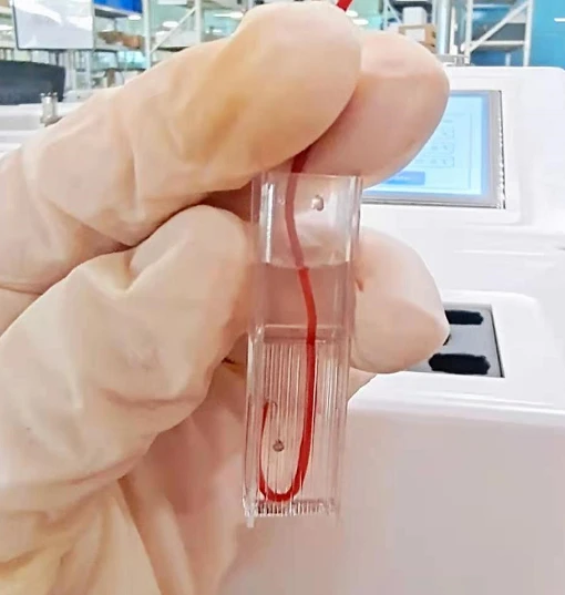
Figure 50
As shown, rotate the sheet metal, take out and place well the cuvette.
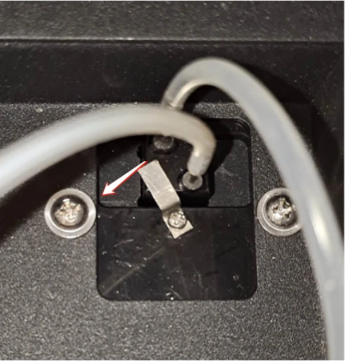
Figure 51
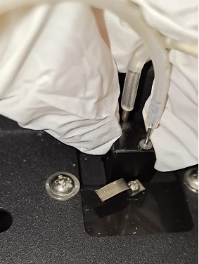
Figure 52
Put the tube into the incubator shows like below:
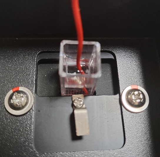
Figure 53
• When the value of the thermometer is stable, click the input box of [Actual Temp] and enter the measured value.
• Click [Calibrate], the displayed temp value would be calibrated to the measured one. If the displayed temp is lower than the set temp, the heating system would work and heat the cuvette. Otherwise, the heating system would not work and would cool down to the set temp slowly.
Temp calibration of incubator:
Put the tube into the incubator shown below, the steps of temp calibration are the same as that of cuvette.
![• When the value of the thermometer is stable, click the input box of [Actual Temp] and enter the measured value., • Click](https://biolabscientific.com/content/manual/20260922002/When-the-value-of-the-thermometer-is-stable-i72-Biolab.webp "• When the value of the thermometer is stable")
Figure 54
Attention:
• This function can only confirm whether temperature monitoring is right or not. When testing a sample, the temperature would be changed according to the test program.
• If the displayed temp is lower than the preset temp, meanwhile the actual temp is higher than the preset temp and continues to increase, maybe there is something wrong with the temperature sensor.
2.Aspirate format
Aspirate format includes the settings of aspirate format and air gap. Click the [Aspirate Format] on the [Reserved Setting] menu, the interface shows as below.
![2.Aspirate format, Aspirate format includes the settings of aspirate format and air gap. Click the [Aspirate Format] on the](https://biolabscientific.com/content/manual/20260922002/2.Aspirate-format-i73-Biolab.webp "2.Aspirate format")
Figure 55
Click to choose the format of aspirate:
[Normal Format]: Only aspirate samples with set volume during normal format.
[Express Format]: After the instrument has aspirated the set volume of the sample, pause and then continue to aspirate the sample that set volume in the [Air Gap].
In order to avoid the interference of the air in the suction probe to the sample aspiration accuracy, the user can choose express aspirate format. Click the box after [Air Gap], pop up a soft keyboard to enter the compensated volume of air.
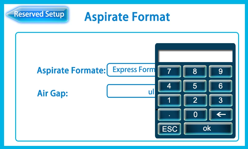
Figure 56
3. Plate calibration
Plate calibration is used to set the optimum position of the filter plate. Click the [Plate Calibration] on the [Reserved Setting] menu, the interface shows as below.
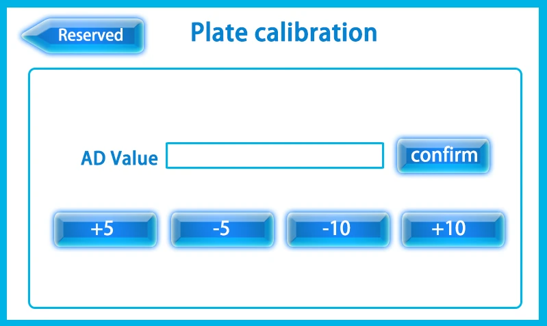
Figure 57
Activate the stepping motor through pressing [+5], [-5], [+10], [-10] to adjust the position of the filter plate. When the [AD Value] is the maximum value, click [Confirm] to save the position parameters of the filter plate.
Attention:
Click the [Data Reset] on the [Reserved Setting] menu, then all the parameter settings would be restored and all the tests and results would be deleted. Reconsider before clicking [Data Reset]. The interface shows like that:
![Attention:, Click the [Data Reset] on the [Reserved Setting] menu, then all the parameter settings would be restored and all](https://biolabscientific.com/content/manual/20260922002/Attention-i76-Biolab.webp "Attention:")
Figure 58
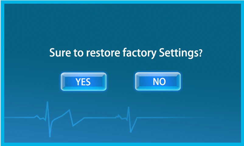
Figure 59
5.1.3 Optical paths calibration
Click [Filter] on the main menu and enter the sub-menu [Filter Test].
![5.1.3 Optical paths calibration, Click [Filter] on the main menu and enter the sub-menu [Filter Test]., Figure 60 BANA-806](https://biolabscientific.com/content/manual/20260922002/5.1.3-Optical-paths-calibration-i78-Biolab.webp "5.1.3 Optical paths calibration")
Figure 60
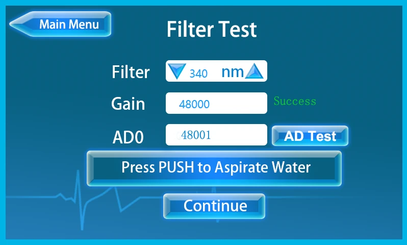
Figure 61
[Filter]: Click or to choose different optical paths for calibration, if the filter is 0, it represents the detection of background value.
[Gain]: Set the target value of optical path amplification, the instrument would automatically increase AD value. If the AD value is equal to the target value, it would display [Success]. If the target value cannot be reached, it would display [Fail].
The calibration steps are as follows:
• Choose the optical path and set target value.
• Insert the suction probe into the distilled water, press the PUSH button to aspirate water.
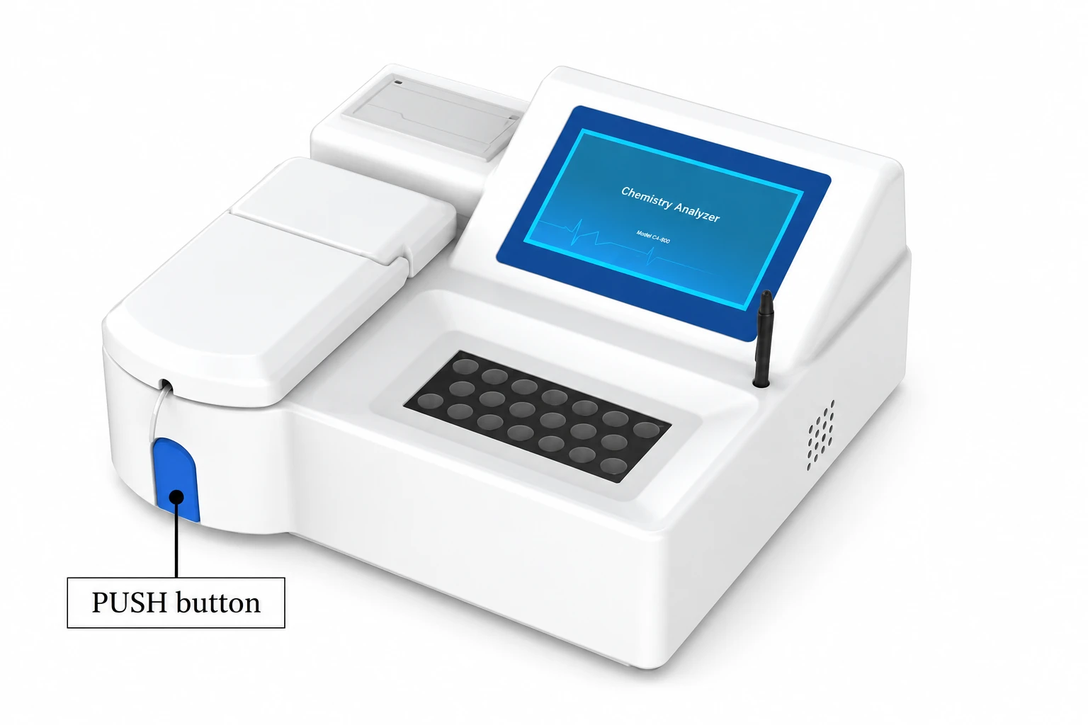
Figure 62
• Click [AD Test] for calibration. The difference between [Gain] and [AD0] cannot exceed 1000.
• Click [Continue] to enter the interface as shown below:
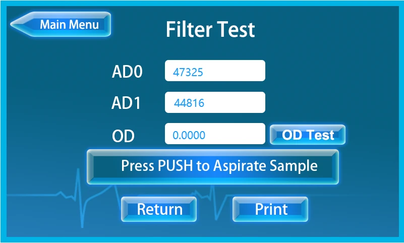
Figure 63
• Insert the suction probe into the sample, press PUSH button to aspirate sample for aspiration testing.
• Click [Print] to print the calibration result of the filter.
• Click [Return] to calibrate again.
5.1.4 AD blank check
When the user finishes the calibration of optical paths, click [Blank] on the main menu and enter the sub-menu [AD Check].
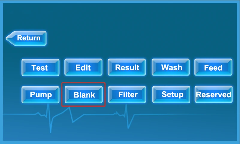
Figure 64
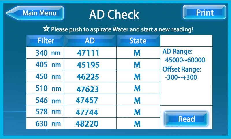
Figure 65
• Insert the suction probe into the distilled water, press PUSH to aspirate water.
• Click [Read] in the interface to read the AD value of all optical paths at one time. In the [State] bar, use letter H, M, L and No to judge the result is high, medium or low.
• Click [Print] can print the test result.
5.1.5 Pump calibration
When the aspiration volume of the instrument is not accurate, the user can calibrate the pumping steps as follows:
• Click [Pump] on the main menu and enter [Pump Calibration].
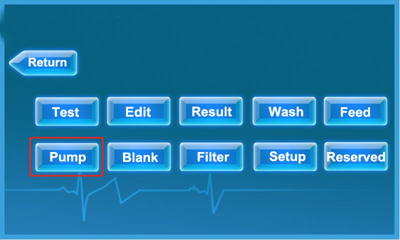
Figure 66
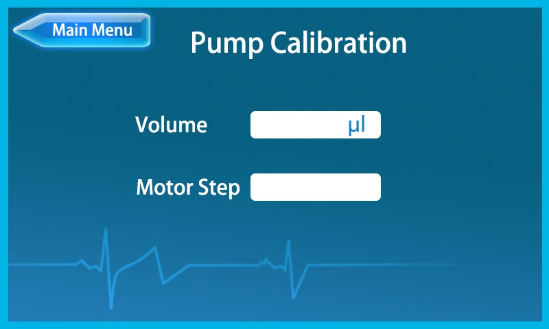
Figure 67
• Input calibration volume and take the same volume of distilled water in jug. Insert the suction probe into the bottom of the jug and then press "PUSH button" to aspirate distilled water.
• When the liquid level drops to the target height (initial volume - set volume) immediately press the "PUSH button" key, and the number of steps of the peristaltic pump motor is calibrated. (For example, when the volume is 400μl, the motor steps is about 6500 to 9000).
• Click [Main Menu] to save and return to main menu, it would pop up an interface to ask if you want to save the changes, click [YES] to save.
• If the aspirate volume is not accurate during the sample testing process, please repeat the above operations or directly modify the current motor step of the instrument through the soft keyboard.
5.1.6 Program process
Click [Edit] on the main menu and enter the sub-menu [Program Process] as shown below.
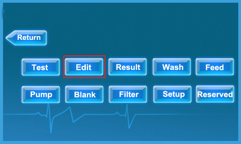
Figure 68
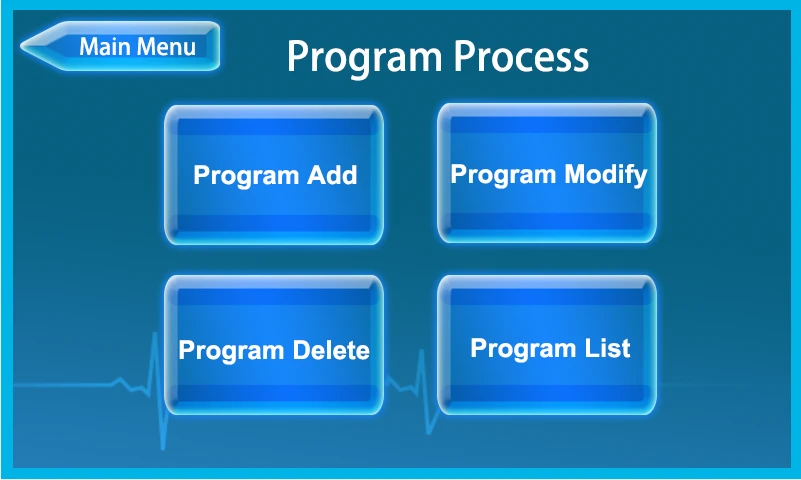
Figure 69
The user can click the keys shown above to enter the sub-menu for adding, modifying, deleting or printing programs.
1. Program add
Before adding a new program, it's necessary to set parameters according to the reagent specification. The program must choose the right analysis method. The commonly used analysis methods are kinetic method, two-point method and End point method. Usually, enzyme programs adopt kinetic methods. Creatinine and urea tests adopt the two points method, and others are used by the end point method. Take program ALB as an example, the operation steps of program parameter setting shown as below:
• Click [Program Add] to enter the interface as shown follow:
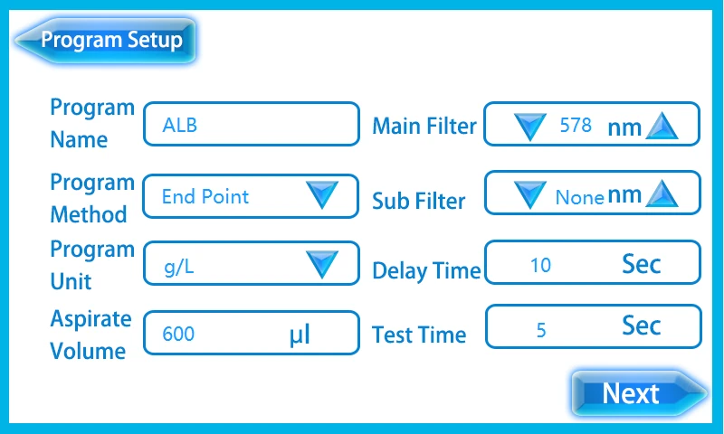
Figure 70
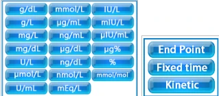
Figure 71
[Program Name]: Input the name through the soft keyboard.
[Program Method]: Click to choose an analyse method between [End Point], [Two points] and [Kinetic].
[Program Unit]: Click to choose the program unit.
[Aspirate Volume]: 100 to 1000 μl, input the volume of sample to be aspirated during the test through the soft keyboard.
[Main Filter]: Click or to choose an optical path.
[Sub Filter]: None.
[Delay Time]: Delay time before test, 1 second to 999 seconds, refer to reagent specification to enter value through soft keyboard.
[Test Time]: 1 second to 999 seconds, refer to reagent specification to enter value through soft keyboard.
• Click [Next] to enter next page:
![• Click [Next] to enter next page:, Figure 72 BANA-806](https://biolabscientific.com/content/manual/20260922002/Click-Next-to-enter-next-page-i90-Biolab.webp "• Click [Next] to enter next page:")
Figure 72
[Linearity Low]: Refer to reagent specification to enter value through soft keyboard.
[Linearity High]: Refer to reagent specification to enter value through soft keyboard.
[Blank]: Click o select the type of blank test in [Water], [Reagent] or [Serum], in order to check and correct the optical path system.
[Num of Blank]: The number of blank tests, which can be entered through the soft keyboard 0~7, the default number is 1.
[Blank Low]: Blank low value. Refer to reagent specification to enter value through soft keyboard.
[Blank High]: Blank high value. Refer to reagent specification to enter value through soft keyboard.
[Normal Low]: Normal low value. Refer to reagent specification or clinical reference value to enter value through soft keyboard.
[Normal High]: Normal high value. Refer to reagent specification or clinical reference value to enter value through soft keyboard.
• Click [Next] to enter next page:
![• Click [Next] to enter next page:, Figure 73 BANA-806](https://biolabscientific.com/content/manual/20260922002/Click-Next-to-enter-next-page-i91-Biolab.webp "• Click [Next] to enter next page:")
Figure 73
[Num of STD]: Quantity of standard samples, which depends on calibration method.
No. of STD | Calibration Method |
1 | End-point Method (Factor Method) |
2 | Two points Method (Fixed Time Method) |
6 | Kinetic Method (Rate Method) |
Table 4
[STD]: Standard No., which is used in two points method and kinetic method, click ![[STD]: Standard No., which is used in two points method and kinetic method, click or to choose. BANA-806](https://biolabscientific.com/content/manual/20260922002/STD-Standard-No.-i92-Biolab.webp "[STD]: Standard No.") or to choose.
or to choose.
[CONC]: Concentration, which represents the standard concentration corresponding to the STD No., entered through a soft keyboard.
[Factor]: Standard factor, which is entered through a soft keyboard according to the reagent specification. The standard factors can also be obtained by an STD test.
[Control]: Click or to choose the type of QC, such as high value QC, median value QC and low value QC.
[Control Value]: Set the target value of QC through the soft keyboard.
[Cuvette Temp]: The preset temperature of cuvette, the default value is 37°C.
[Dilution Factor]: The sample dilution factor, by default, is 0, which can be entered by soft keyboard, and the test result is multiplied by the corresponding dilution factor.
• Click [Done] to enter the interface as shown below, click [YES] to add the program, click [No] to back to the main menu interface, click [Cancel] to back to the interface of parameters edit.
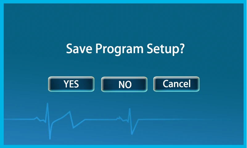
Figure 74
2.Program modify
Modify and view the parameters of the added program. When the reagent type or batch number is changed, the corresponding parameters need to be modified. The modification steps of the program are as follows:
• Click [Program Modify] to enter the interface as shown follow:
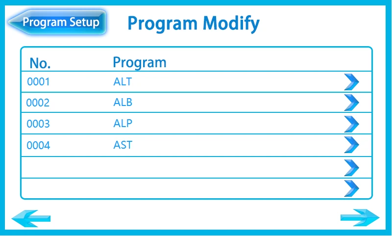
Figure 75
• Choose the program you need to modify, click to enter the interface of program parameters, and then modify the parameter that needs to be modified.
• Click [Done] to enter the saving interface, and click [YES] to save the edit of the program.
3. Program delete
• Click [Program Delete] to enter the interface as shown follow:
![3. Program delete, • Click [Program Delete] to enter the interface as shown follow:, Figure 76 BANA-806](https://biolabscientific.com/content/manual/20260922002/3.-Program-delete-i95-Biolab.webp "3. Program delete")
Figure 76
Choose the program and click  , then pop up an interface:
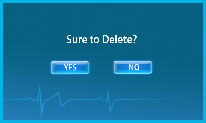
• Click [YES] to delete the program, click [No] to back to the interface of parameters edit.
4. Program list
• Click [Program List] to enter the interface as shown follow :
![4. Program list, • Click [Program List] to enter the interface as shown follow :, • Click the , the instrument would print](https://biolabscientific.com/content/manual/20260922002/4.-Program-list-i98-Biolab.webp "4. Program list")
• Click the , the instrument would print the program information.
• Click [Print List], the instrument would print the program list, including the program number and name, for users to query for program numbers.
5.2 Daily Operation Process
5.2.1 Instrument preheating
Connect to the power and turn on the switch, the instrument should be preheated for 30 minutes.
5.2.2 Pipeline washing
Clean the cuvette and pipe line before testing, insert the suction probe into distilled water, and then click [Wash] on the main menu to start washing, repeat 5-10 times.
Attention:
Work in an environment that is dust proof, moisture proof, and in which installation air conditioning is better and environment temperature in 18-25 °C.
• When external power is not stable, instruments must connect regulated power supply.
• Instruments in the process of operation should not open the cover, so as not to cause damage to equipment or operator.
• With leakage and electrostatic prevention, the instrument should be in good grounding. Line power socket must have a reliable grounding line to guarantee in a steady state and security.
• After work, wash the instrument 3 times at least immediately to keep the cuvette and pipeline from waste attachment.
• After finish the testing, the used should be collected and disposed according to the requirements of the disposal of the medical waste.
• The waste pipe end should not be dipped into the waste to avoid poor drainage.
• Use qualified reagents within the period of validity.
5.2.3 Program test
Click [Test] on the main menu to enter the sub-menu [Test] as shown below:
![5.2.3 Program test, Click [Test] on the main menu to enter the sub-menu [Test] as shown below:, Figure 77 BANA-806](https://biolabscientific.com/content/manual/20260922002/5.2.3-Program-test-i99-Biolab.webp "5.2.3 Program test")
Figure 77
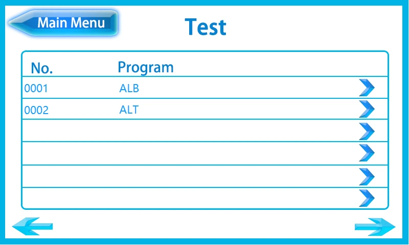
Figure 78
Take program ALB for example to show the test progress. Click to enter the interface as shown below:
1. Temperature calibration
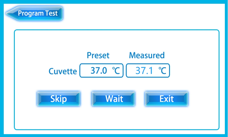
Figure 79
• [Skip]: Go to the next step.
• [Wait]: When the cuvette reaches the set temperature, it would automatically proceed to the next step.
• [Exit]: Back to the main menu.
After calibrating the temperature, click to proceed to the next step.
2. AD auto zero
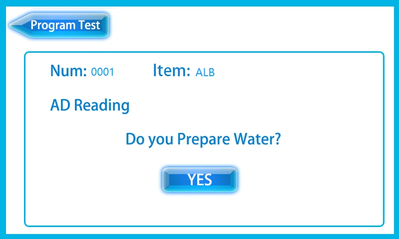
Figure 80
Confirm that the suction probe is inserted into distilled water and click [YES] to enter the interface as shown below:
![Confirm that the suction probe is inserted into distilled water and click [YES] to enter the interface as shown below:,](https://biolabscientific.com/content/manual/20260922002/Confirm-that-the-suction-probe-is-inserted-into-distilled-water-and-i103-Biolab.webp "Confirm that the suction probe is inserted into distilled water and")
Figure 81
Press the PUSH button to aspirate distilled water, the instrument would automatical