Get Quote ▼
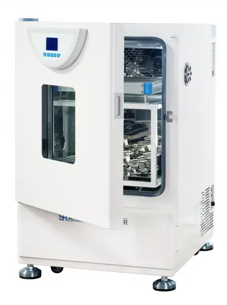
Floor Standing Shaking Incubator BSFT-104
- LCD Microprocessor Controller (with timing function)
- • Large LCD screen to display more data at same time.
- • R134a refrigerant, imported compressor and fan motor.
- • Big observation windows.
- • 304 Stainless steel chamber and platform, easy to clean.
- • There is a 25mm instruction connection hole on the left side of the chamber for easy testing operation and temperature measurement.
- • The parameters can be automatically stored in case of power failure, and it will continue run as presetting program after turn on.
- • Microprocessor PID controller for temperature and shaking speed with timing function.
 Get Quote
Specifications
| Model | BSFT-104 |
| Electrical Requirement | 220V 50Hz |
| Shaking Speed Range | 40~300r/min |
| Amplitude | 20mm |
| Temperature Range | 4~65°C |
| Display Resolution | ±0.8°C (Test point is 37°C) |
| Power Consumption | ±0.2°C (Test point is 37°C) |
| Platform Size | 0.1°C |
| Default Platform | 950W |
| Timing Range | 400x300 |
| Exterior Dimension (WxDxH)mm | 635x714x1055 |
| Timing Range | 0~5999min |
| Packing Dimension | 76*87*125 |
| CBM | 0.83 |
| Net Weight | 115.00 |
| Gross weight | 152 |
Features
• Large LCD screen to display more data at same time.
• R134a refrigerant, imported compressor and fan motor.
• Big observation windows.
• 304 Stainless steel chamber and platform, easy to clean.
• There is a 25mm instruction connection hole on the left side of the chamber for easy testing operation and temperature measurement.
• The parameters can be automatically stored in case of power failure, and it will continue run as presetting program after turn on.
• Microprocessor PID controller for temperature and shaking speed with timing function.
• The ultraviolet lamp can sterilize the chamber regularly.
Safety:
• Safety door switch, auto pause operation when door is opened.
• Smooth start and stop system prevents liquid spillage.
• Auto-controller of fan speed to prevent damage to the samples.
• Self-diagnosis function, it will display error when failure.
Option:
• Temperature-limiting alarm system, auto switch off when over-temperature.
• RS485 connector or USB interface can connect computer record and inspect the parameters
and the variations of temperature.
• Intelligent programmable temperature controller.
Operating Manuals
 Download Manual (PDF)
1. Safety Precautions
2. Brief Account of the Product
2.1 Front View
2.2 Features of structural function
3. Main Technical Parameters
4. Method to Operate the LCD Controller
4.1 Drawing of controller panel
4.2 Description of pilot lamp
4.3 Description of keys
4.4 Operating procedures
4.5 Alarm function
4.6 Setting of internal parameters
5. Method of Operation
5.1 Working environment
5.2 Operational procedure
6. Maintenance and Precautions
7. Troubleshooting
1. Safety Precautions
! Danger(It may cause serious loss in property or injuries and deaths
1. This product must be earthed reliably and kept far away from electromagnetic interference source(Zero line or neutral line should never be used as earth wire.
2. Make sure before use the voltage and frequency of power meet the requirements of the product.
3. The product should be connected to a separate power outlet and both the plug and outlet are earthed properly.
4. It is not allowed to pull off or insert the power plug wantonly without turning off the power switch while the product is in operation.
5. It is not permissible to lengthen or shorten the power line at random.
6. No repairs may be done without permission and the equipment must be maintained by an electrician entrusted by our company.
! Caution(It may cause serious loss in property or injuries and deaths)
1. Operation shall be done only after the directions for use are read and understood fully.
2. As304 SS inner container is not acid-resistant, anti-corrosive measures should be adopted and acidic medium should never be used in the incubator!
3. The power line should never be drawn directly when pulling off the plug.
4. In one of the following cases, the power plug must be pulled off:
4.1 Replacement of fuse.
4.2 Under inspection and repair when the product fails.
4.3 Suspension from use for a long time.
4.4 In movement.
! Caution(Otherwise its service life may be affected, resulting in its inability to work regularly)
1. When in movement, the product should have a tilt angle of not bigger than 45 degrees to avoid damage to the refrigerating system.
2. When put into position, the product should stand for one day or two before startup to ensure normal operation of the refrigerating system and prolong service life.
3. The product shall be mounted on a solid and firm plane, keeping it horizontal.
4. Some space shall be left around the product.
5. The product must be put into use under given working conditions.
6. Never open/ close the box door with a force, otherwise the door will fall away and the product injured, causing casualties.
7. In case of suspension from use for long, the product should be dehumidified regularly to avoid damage to relevant devices.
2. Brief Account of the Product
2.1 Front View

Figure 1
2.2 Features of structural function
• Integration of thermostatic incubator and shaker for dual purposes.
• Adoption of SS inner container with semi-arc corners for ease of cleaning.
• Glass inspection window and lighting system facilitates observation of culture.
• Installation of UV germicide system: UV germicide lamps can sterilize the inside of the body to prevent pollution effectively.
• The intelligent LCD controller can ensure accurate and reliable temperature control in the working chamber.
• Duct for cold and hot airstream is mounted in the body and operation of blower fan will enhance smooth air circulation and improve temperature uniformity in the working chamber.
• 0~99 hour and 59 minute timing and over-temperature alarm function.
• Use of environmentally-friendly Freon-free compression with such functions as time delay and over-heat protection.
• Door switch with opening and auto-stop function.
• Low-noise AC motor facilitates stepless speed regulating.
3. Main Technical Parameters
Model of product | BSFT-104 (single layer) |
Input power | 950W |
Range of temperature control | 4~65°C |
Temperature resolution | 0.1°C |
Temperature fluctuation | ±0.5°C |
Hunting speed | 40-300rpm Precision:≤±2rpm |
Amplitude | 20mm |
Timing range | 0-99 hours 59 minutes |
Load of oscillator tray | ≤10kg |
Size of tray8 | 400x340(mm) |
Size of working chamber | 505x400x500 (mm) |
Overall dimension | 635x730x980 (mm) |
Table 1
4. Method to Operate the LCD Controller
4.1 Drawing of controller panel

Figure 1
4.2 Description of pilot lamp
1)PV display.
2)PV1: Showing measurement speed.
3)SV1:Showing set speed.
4)PV2: Measured temperature.
5) SV2:Showing set temperature.
6) Pilot lamp for operation (RUN):Indicating the state of the controller, it lights up when the controller is running and it is put out when the controller stops.
7)Heating lamp: It lights up when the heating output.
8)Cooling lamp: It lights up when the cooling output.
9) Alarm lamp: It lights up when alarm light.
10) Pilot lamp for blower: It lights up when the blower works.
11) Mute indicator lamp: It lights up when the alarm and press any key mute.
12) Program display: when a program section, PROG light.
13)Circulating fan: when fan light is flashing at low speed, and the lamp is going on a long time at high speed.
4.3 Description of keys
① Add key: Under the set mode, click this key and one number will be added, pressing
this key without stop the number will be increased continuously.
Mode key: It is used for changing the set value, calling out parameters or confirming the change in parameters.
③ Start/stop key: Pressing this key for over 4 seconds will control start /stop of the program.
④ Decrease key: Under the set mode, click this key and one number will be decreased pressing this key without stop the number will be decreased continuously.
⑤ Under the set mode, clicking this key will effect shit and under the standard mode.
4.4 Operating procedures
1)temperature setting: Clicking and pressing MODE key once,"SV2" is flashing, indicating temperature can be set as required. Using the add key, decrease key or shift key, you can set required temperature. If you press MODE once more, you can set speed.
2)speed setting: If you click and press MODE twice, "SV1"character will emerge, indicating the speed can be set as required. Using the add key, decrease key or shift key, you can set required speed. If you press MODE once more, you can set timing.
3)timing function: When "TIME" is flashing, we can setting timing. Timing function to cancel; when time is set as 0, timing function will be cancelled; if time is not set as 0, the controller will perform the timing function;
When the set time is up, "END" will be displayed on SV screen. When the buzzer sounds, it can be silenced by pressing any key.
Note: ①For each change of a parameter, it is necessary to press "MODE" key for
confirmation to validate the change.
②After all the parameters are set, press "START/STOP" key for about 4 seconds restart the controller running the new parameter.
4.5 Alarm function
① When the measured temperature is in excess of the set temperature by 3°C, the instrument will buzz and cut off heating automatically. The buzzer can be silenced by pressing any key.
② When the motor overloads for more than 10 seconds due to excessive oscillating load, the instrument will give a buzzing sound. When oscillation stops, the buzzer can be silenced by pressing any key.
③ The fixed run time is count down. When time is set as"0", it is long-term operation. After fixed -time run is over, it will stop automatically. The instrument will give a buzzing sound. The buzzer can be silenced by pressing any key.
④ When such faults as wire-break and short-circuit occur to Pt100 and the measured temperature is higher than 60°C or lower than -1.0°C, "------"will be shown in the LCD screen.
4.6 Setting of internal parameters
Under the standard status click and press the function key for long time, when the screen displayed LK, enter password enter into the set menu. Every function parameter will be change the control effect. When you one minutes press" " key, return to the standard mode, may be some function parameter are not changed:
(1) When the output area on LCD screen displays LK, press add-subtract key or shift key to let LK=0000 and pressing SET key may allow you to enter into setting of user's parameter hierarchy.
Prompting character | Name | Setup scope | Description | Initial value |
dy | Selection of prestart | 0-99:99 | 0: no prestart: for other values, start after auto-delay for dy time by starting the run key. |
Table 2
(2)When the output area on LCD screen displays LK, make LK=0003. You can enter into setting of manufacturer's parameter hierarchy only by pressing SET key.
The menu of manufacturer's parameter hierarchy is as follows:
Prompting character | Name | Setup scope | Description | Initial value |
tM | Setup of maxi temperature permissible by the instrument | To be set up within the measurement scope | Stop heating beyond maxi temperature and give alarm. | |
PO | Boot mode | 0~2 | when PO =0, after open the power, the controller in a stopped state, by long press star/stop key is up and running. when PO =1, after open the power, the controller will be running. when PO =2, running from last power began to run. | |
AL | Setup of alarm | 0.0-100.0 | When temperature surpasses SP+AL value, alarm lamp will light up with alarm output (with function of HOLD). | |
Pb | Zero adjustment (intercept) | -100.0~100.0 | When the zero error of the instrument is greater and the full scale error is smaller, the value should be adjusted. As a rule with Pt100 the value is seldom adjusted. | |
PK | Adjustment of full scale (slope) | -1000~1000 S | When the zero error of the instrument is smaller and the full scale error is greater, the value should be adjusted. PK=4000x (specified value-actual display value)/actual display value and as a rule with Pt100 the value is adjusted first. | |
PA | Onboard room temperature sensor correction | -30-30 | When there is an error between the on-board room temperature sensor and the actual situation, adjust the value. |
Table 3
A change in each functional parameter may lead to varied control effect. If "MODE" key is not pressed within one minute, it will return to the standard mode automatically as possibly some functional parameter has not be change.
5. Method of Operation
5.1 Working environment
a. Ambient temperature: 15°C~35°C.
b. Relative humidity not bigger than 85%.
c. Power source: AC 220V 60Hz.
d. Atmospheric pressure: 86kPa~106kPa.
e. Height above sea level not greater than 2000 m.
f. No strong sunlight, no corrosive gas, no intense shock source and strong electric magnetic field around with good ventilation.
5.2 Operational procedure
1) The ware to be shaken is fixed onto the beaker clamp with its mouth sealed and box door closed tightly.
2) Power switch is turned on after the plug is inserted into the outlet.
3) Necessary parameter is set as required.(refer to Section 2.2 in the Method to Operate LCD Controller)
4) At the end of operation the equipment is disconnected from the mains-supply and excess water in the working chamber is wiped off.
5) If the equipment is run under low temperature(lower than room temperature)for long or the cooling effect is undesirable(slowing cooling or with static difference), it should be defrosted at an interval of half a month: The equipment is made to work for more than 2 h under 50°C and then necessary parameter is reset before operation.
6. Maintenance and Precautions
1. When the equipment is moved, the tilt angle in any direction should be less than 45 degrees, otherwise it may cause damage to the cooling compressor or make cooling performance abnormal.
2. When the equipment is put into place, it should stand for a day or two before start to ensure normal operation of the compressor and prolong its service life.
3. To ensure stability and low noise in operation,the equipment must be placed steadily and smoothly.
4. To ensure sufficient heat dissipation space for thermostatic effect, the equipment must be away from the wall and other objects by a minimum distance of 20 cm.
5. This equipment must be earthed reliably and kept away from electromagnetic interference source.
6. When no lighting is required in the equipment, the switch should be turned to the Off position so as not to affect temperature in the box.
7. The compressor will be started after a time delay of 3 minutes.
8. If the equipment is to be used under an ambient temperature of over 30 °C,it is suggested that intensified ventilation measures be adopted at the back and ambient temperature lowered(For example, installation of an air-conditioner to raise the working temperature to about 25°C)to prevent the compressor from being dead due to overheat.
9. Never put your finger, rod or other foreign matter into the air vent or inlet. As the internal fan is in high-speed operation, any contact with it will lead to damage to the equipment or personal injury.
10. If any abnormality(smell of scorching)is found, the power plug should be pulled off immediately to stop the equipment. Continuation of abnormal state will lead to fire or electric shock due to overheating.
11. The fix screw of beaker clamp should be checked often to prevent noise or the clamp from separation.
12. The box door should not be opened at will, otherwise thermostatic effect will be affected.
13. The box should be kept clean outside with transparency of glass. Its surface should never be wiped with acid, alkali or other corrosive solution.
14. For suspension of the equipment moisture should be trapped as follows: The equipment is run under a set temperature of 50°C for consecutive 5 hours under the mode of dehumidification and the box door is opened every two hours to release moisture. After the treatment is over, the power plug is pulled off for custody.
15. Recheck if the technological requirements comply with the set instrument parameters before each use, reuse after long suspension or any change in technological requirements or environmental conditions.
16. If the culture in the box is expensive, you have to contact us to add a separate protective system for timely supervision over the operating condition of the product.
17. For long suspension, the power plug should be pulled off to avoid accidents. The equipment should be operated regularly (for one quarter as a rule)under the working conditions for 2-3 days to trap moisture in the electrical components and avoid any damage to related devices.
18. The equipment should be repaired by qualified personnel and our after-sale service center should be contacted first before maintenance.
19. If you require technical support or return the equipment for repairs,please also get in touch with our after-sale service center. Upon return of the equipment you are requested to enclose a brief account of failure, keep the equipment erect and straight in transit and have it packaged properly.
We assume no liability for any damage arising from poor packing!
7. Troubleshooting
Serial No. | Symptom | Potential source | Corrective action |
1 | Power fails after startup | No power in the outlet or poor contact | Check and repair |
Power lead broken | Replace | ||
Power switch not turned on or broken | Turned on(off)or replaced | ||
Fuse not fixed or burnt | Usable fuse tube fixed, find out the cause and start after repairs | ||
2 | No operation after startup | Power of controller not turned on or run key not pressed | Do as shown in the directions |
Parts of controller or motor are out of order. | Replace | ||
3 | "-----"shown on the screen | Sensor Pt100 out of order | Repair. Pt100=0°C,100Ω About 0.3Ω is increased for |
4 | No heating up or no heating up after heating up a little while | Set temperature lower than RT(Room temperature ) | Resetting |
Start timing function St≠0 | Insufficient timing. Resetting enough time or let St=0 T=0 | ||
No voltage output from controller | Controller out of order. Replace or repair. | ||
Voltage available at both ends of heating pipe | Connector of heating pipe separated or out of order | ||
Door switch fails | Adjust hasp position or replace the broken switch | ||
5 | Great error in actual temperature | Accuracy is out of tolerance | Zero or full scale correction |
6 | Static difference or overshooting | Improper set parameter | Set temp. value |
7 | Temperature out of control | Heater out of order | Replace |
Controller out of order | Replace | ||
Blower doesn't turn and lower temperature in the working chamber | Repair and replace | ||
8 | Much noise (with refrigerating blower ) | Not placed steadily and screws that fix blower pallet and flask clip are loose. | Repair |
9 | Shaker doesn't work or out of control | Light-on is out of order or connecting wire is in poor contact | Replace light-on and repair. |
Control panel out of order | Control panel replaced. | ||
Motor doesn't turn, | Motor out of order or overload, poor contact of door switch or broken. Replace and repair. | ||
Door switch fails., | Adjust hasp position or replace the switch | ||
10 | It doesn't turn. | Mechanical transmission device got stuck | Hand-propelled test |
Start torque too small | Do as shown in the directions with increased rA |
Table 4
Packing List
Serial No. | Category | Description | Unit | Quantity | Remarks |
1 | Document | Directions for use | Copy | 1 | |
2 | Document | Packing list | Copy | 1 | |
3 | Spare part | Core of fuse | 2 | ||
4 | Spare part | UV tube | 1 | 8W |