Get Quote ▼
BOD Incubator BIBD-201
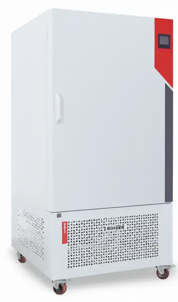
- The shell is made of cold-rolling steel with static spray plastics, the working chamber is made of mirror stainless steel, the shelves can be adjusted optionally;
- PMMA II operating system, with over temperature alarm and self-diagnosis function;
- Color LCD backlight display;
- With screen lock time, screen saver password setting function, to prevent operation at will;
- Programmable design, it can be set 30 segments 99 cycles;
- Use centrifugal fan to make the temperature of the working room uniform and stable;
- Observation glass inner door;
- Test holes are equipped on both sides, internal diameter is 30 mm;
 Get Quote
Specifications
| Model | BIBD-201 |
| Volume [L] | 100 |
| Type | Biochemical Incubator |
| Temp. Range [°C] | 0~70 |
| Temp. Resolution [°C] | 0.1 |
| Temp. Fluctuation [°C] | ±0.5°C (heating) ±0.7°C (cooling) |
| Temp. Uniformity at 37°C [°C] | ±1 |
| Power [W] | 1000 |
| Timer Range [min/h] | 0~9999 |
| Reservation Range [min] | 0~9999 |
| Internal Dimensions WxDxH [mm] | 490x390x610 |
| Housing Dimensions WxDxH [mm] | 630x680x1250 |
| Number of Shelves (std./max.) [pc] | 2 / 4 |
| Load per Shelf [kg] | 15 |
| Net Weight/Gross Weight [kg] | 91/109 |
| Package Size [mm] | 730x820x1440 |
Features
PMMA II operating system, with over temperature alarm and self-diagnosis function;
Color LCD backlight display;
With screen lock time, screen saver password setting function, to prevent operation at will;
Programmable design, it can be set 30 segments 99 cycles;
Use centrifugal fan to make the temperature of the working room uniform and stable;
Observation glass inner door;
Test holes are equipped on both sides, internal diameter is 30 mm;
The fan has 6-stage speed regulation;
With reservation and timing function;
Equipped with mechanical lock;
Equipped with 220V power socket;
Equipped with fluorescent lamp in working chamber (mould incubator is equipped with UV light);
Adopt imported compressor unit, low noise, stable performance;
Power supply recovery function, data will not be lost when power failure and system halted.

Shelf

Light

Glass Lock Group
Operating Manuals
 Download Manual (PDF)
1. Notify
2. Safety warning signs, marking description
3. Safe operation precautions
4. Product related (scope of application, working principle, technical parameters)
4.1 Application scope of the product
4.2 Product working principle
4.3 Technical specification
5. Product structure
5.1 Control panel
6. Equipment installation
6.1 Installation site
6.2 Install
6.3 Preparation for operation
7. Operation method
7.1 Set the status
7.2 Parameter view
7.3 Lock screen
7.4 Internal parameter status
8. Alarm and security features
9. Daily use and maintenance
10. Trouble Removal
11. Specification configuration sheet
12. Product packing list
1. Notify
• In order to ensure the safe use of this equipment, please read this manual carefully before use.
• Be sure to store this manual in a place convenient for users of the equipment.
• The company does not undertake safety guarantee for the use and operation methods other than those specified in this manual.
• This instruction manual is for the use of equipment users and maintenance personnel, please keep it properly.
• Due to the improvement of product function and performance, the equipment may be changed without prior notice.
• This instruction manual may not be reproduced in any form without the written permission of the Company.
2. Safety warning signs, marking description
This manual has important safety information, please be sure to follow it.
Be sure to keep this manual in a place where users of the device can easily access it.
The contents of the signs described in this section will appear on the device and in this manual to enable you to operate and use the device safely and correctly, and to protect the user or any other person from possible injury.
•"Warning" sign
 Warning:
Failure to comply with the warning signs may result in serious injury or death to persons.
•"Attention" sign
Attention:
Failure to follow the caution signs may result in injury or damage to equipment and related property.
Meaning of logo
![]() Prohibited
Prohibited
![]() Followed
Followed
The identification on the device
 Alternating
 Protective conductor terminal
 Power on
 Power off
Warning, attention, caution, danger
3. Safe operation precautions
Warning
![]() The equipment shall not be placed outdoors for use. If the device is wet with rain, it may leak Electricity and electric shock。
The equipment shall not be placed outdoors for use. If the device is wet with rain, it may leak Electricity and electric shock。
 This device can only be installed by qualified engineering and technical personnel or maintenance personnel, such as unqualified personnel It may cause electric shock or fire.
The equipment should be installed on a solid ground and due care should be taken to prevent the equipment from tipping over. If the ground is not enough
If the installation site is not suitable, the equipment may tip over or overturn, resulting in injury.
![]() Do not install the device in a wet area or in a place where water may splash. Otherwise it will be due to insulation
Do not install the device in a wet area or in a place where water may splash. Otherwise it will be due to insulation
The degree is reduced and causes accidents such as leakage or electric shock.
![]() Do not install the device in a place where flammable or volatile materials are stored. Otherwise it may be caused explosion or fire
Do not install the device in a place where flammable or volatile materials are stored. Otherwise it may be caused explosion or fire
![]() Do not install the device in an area with acidic or corrosive gases. Otherwise it will be caused by corrosion leakage or electric shock.
Do not install the device in an area with acidic or corrosive gases. Otherwise it will be caused by corrosion leakage or electric shock.
Use power outlets with ground wires to prevent electric shock. If the power socket is not grounded, ensure that qualified engineers install the grounding cables.
![]() Do not ground the device through the gas, water supply pipe, telephone cable, or lightning rod. The above grounding can cause electric shock if the pipe line is not complete.。
Do not ground the device through the gas, water supply pipe, telephone cable, or lightning rod. The above grounding can cause electric shock if the pipe line is not complete.。
Please use the dedicated power supply indicated on the nameplate of the device. The use of any other voltage or frequency of the power supply than that indicated on the nameplate may cause electric shock or fire
![]() If the container is not sealed, do not store volatile or flammable materials in the equipment, otherwise it may cause explosion or fire
If the container is not sealed, do not store volatile or flammable materials in the equipment, otherwise it may cause explosion or fire
![]() Do not insert metal objects, such as nails or wire, into any openings and gaps or into any outlets of the equipment, where accidental contact between such objects and moving parts may result in electric shock or injury.
Do not insert metal objects, such as nails or wire, into any openings and gaps or into any outlets of the equipment, where accidental contact between such objects and moving parts may result in electric shock or injury.
Use this device in a safe area when storing toxic, hazardous or radioactive materials. If used improperly, it may cause harm to human health and the environment.。
Before repairing or maintaining the equipment, turn off the power switch (if any) and disconnect the power supply of the equipment to prevent electric shock or injury.
Warning
![]() Do not touch any electrical parts such as power plugs or any switches with wet hands, as this can cause electric shock.
Do not touch any electrical parts such as power plugs or any switches with wet hands, as this can cause electric shock.
Make sure you don't inhale drugs or particulates around the equipment during maintenance, as this could harm your health.
![]() Do not splash water directly onto the equipment. Otherwise it will cause electric shock or short circuit.
Do not splash water directly onto the equipment. Otherwise it will cause electric shock or short circuit.
![]() Do not place containers of water on the device. Otherwise, leakage or contact may be caused by liquid splashing.
Do not place containers of water on the device. Otherwise, leakage or contact may be caused by liquid splashing.
![]() Do not drag, wrap, bind the power cord, do not damage the power plug. A broken power cord or plug can cause fire or electric shock.
Do not drag, wrap, bind the power cord, do not damage the power plug. A broken power cord or plug can cause fire or electric shock.
![]() Do not use power cords with loose plugs. This type of power cord may cause fire or electric shock.
Do not use power cords with loose plugs. This type of power cord may cause fire or electric shock.
![]() The user shall not disassemble, repair or modify the equipment without the authorization of our factory or the guidance of authorized personnel. Otherwise, it may cause fire or injury due to improper operation.
The user shall not disassemble, repair or modify the equipment without the authorization of our factory or the guidance of authorized personnel. Otherwise, it may cause fire or injury due to improper operation.
If the device is not working properly, remove the power plug. Continued operation under abnormal conditions may cause electric shock or fire.
When unplugging from a power outlet, hold the power plug firmly and do not pull the lead of the power plug. If the wire is pulled by hand, it may cause electric shock or fire due to short circuit.
Remove the power plug before moving the device. Do not damage the power cord. A damaged power cord may cause electric shock or fire.
When the equipment is not used for a long time, the power plug should be unplugged. Failure to do so may result in electric shock, leakage or fire due to deterioration of the insulator.
If the device is left unused in an unsupervised area for an extended period of time, ensure that children do not access the device and that the door is not fully closed.
Equipment disposal should be carried out by the corresponding personnel. The door should be removed to prevent accidents such as suffocation.
![]() Do not put plastic bags in the reach of children, because plastic bags may cause suffocation accidents.
Do not put plastic bags in the reach of children, because plastic bags may cause suffocation accidents.
Attention
After cleaning the dust off the power plug, insert the plug tightly into the socket. A dusty plug or improper connection may cause heat or ignition。
After a power failure or power cut occurs, check the temperature, number of segments, and timing after restarting the device. Otherwise, the stored item may be damaged due to a change in the set value.
If the device is not used for a long time after purchase, store the device in a dry and ventilated environment. If no, when you use it again, the device may be damaged and cannot work normally.
When moving equipment, prepare proper tools or qualified personnel. Do not tip the equipment over to prevent equipment damage or personnel injury.
It should be ensured that there is a sufficient width and height of the handling channel, if the need to move to the second floor or above, should ensure that the elevator can accommodate the size of the equipment, to ensure the safety of the equipment. Ensure adequate space for installation equipment and personnel.
![]() If the container is not sealed, do not store corrosive substances such as acids and alkalis in the device. Otherwise, the components in the container and electrical components may be corroded.
If the container is not sealed, do not store corrosive substances such as acids and alkalis in the device. Otherwise, the components in the container and electrical components may be corroded.
4. Product related (scope of application, working principle, technical parameters)
4.1 Application scope of the product
Biochemical incubator with cooling and heating two-way temperature control system, temperature control function, widely used in environmental protection, health and epidemic prevention, drug testing, agricultural livestock, aquatic research, colleges and universities, production departments, is water analysis and BOD determination, bacteria, mold, microbial culture, conservation, plant cultivation, breeding experiments of special constant temperature equipment.
4.2 Product working principle
The actual temperature sensed by the temperature sensor in the chamber is converted into an electrical signal, and the heater or refrigeration compressor is controlled by a microcomputer to achieve the required temperature
4.3 Technical specification
Model | BIBD-201 | |
Temperature range | Temperature control range(°C) | 0~70 |
Uniformity range(°C) | ±1(37°C) | |
Fluctuation range(°C) | ±0.5(heat)±0.7(refrigeration) | |
Electrical Specifications | Mains input | ~220V ±10V,50/60Hz |
Input power(W) | 1000 | |
Refrigerating fluid | R134 | |
Work environment | environment temperature10~30°C relative humidity70% | |
Equipment class | Class I | |
Table 1
Note: This machine has low temperature automatic frost function, in the low temperature automatic frost temperature will have some fluctuations is a normal phenomenon!
5. Product structure

FIgure 1
Single door product structure diagram (for reference only)
1, Water tray | 2, Compressor | 3, Overflow tube | 4,Door lock |
5, Heater | 6, Heat switch | 7, Evaporator | 8, Shelf |
9, Light | 10,Glass door | 11,Door | 12,Inner door lock |
13,Screen | 14,Reserved interface | 15,Power switch | 16,Control board |
17 ,Wheel |
5.1 Control panel

Figure 2
Key description
1.Setting key: Click to enter the setting state, and long press the key for 3 seconds to enter the internal parameter state;
2.Shift/Reservation key: Click in the setting state and enter the cursor to move; click in the standby state and "ord" will appear to set the reservation time (0.5h increment). Click the reservation key again to enter the reservation countdown page "oln" and start the reservation. Under the reservation countdown, long press the reservation key to cancel the reservation, or click the Run key to exit the reservation and run directly;
3.Reduce/Illumination key: Click or long press this key in the setting state to reduce the set value, click on the main interface to turn on or off the lighting lamp;
4. Add/Query key: Click or long press the key to increase the set value under the setting state. On the main page, click Query key to query the current set temperature ("CP-") and set time ("CT-").
Setting mode:
Set the temperature ("CP-") and set the time ("CT-").
Multi-valued mode:
Set temperature and set time
("CP1" : the current temperature is the temperature set in paragraph 1, "CP15" : the current temperature is the temperature set in paragraph 15)
("CT1" : the current temperature is the time set in paragraph 1, "CT15" : the current temperature is the time set in paragraph 15);
5. Stop/Run key: Click to start running or long press to stop running;
6. Status area Indicator area: Displays alarm, heating, cooling and other status information.
6. Equipment installation
6.1 Installation site
For proper operation and optimal performance, install the equipment in a location that meets the following conditions
Note: Ambient temperature 10~30°C; Relative humidity below 70%
• A location that is protected from direct sunlight.
Do not install the device in direct sunlight. Installation in direct sunlight may cause the device to fail to achieve the expected performance.
• A place with adequate ventilation.
If the device is used in a small and closed room, it may not be able to dissipate heat in time, resulting in the device not working properly. The device must be at least 10CM away from the wall.
• A place away from heat
Avoid installing equipment near heat sources such as boilers or heaters. Excess heat from the outside will affect the expected performance of the equipment.
• A site with solid, level ground.
Install the device on a solid and level ground. An uneven ground or tilted device may cause device failure or injury. Install the equipment under stable conditions to avoid equipment shaking and noise.
• A location that is not prone to high humidity.
Install the device in a place where the humidity is no more than 70%. If installed in a place with high humidity, it may cause leakage or electric shock.
Warning:
Do not use this device outdoors. If the equipment is exposed to rain, it may cause electrical leakage or electric shock.
Do not place the device in a wet place or in a place where water is likely to splash, or it may cause electrical leakage or electric shock due to reduced insulation.
• A location free of flammable or corrosive gases.
Do not install the equipment in a place with flammable or volatile substances, or it may cause an explosion or fire. Or it may cause leakage, electric shock or damage to the equipment due to corrosion.
6.2 Install
1. Remove packing material
After removing all packing materials, open the door and ventilate the equipment. If the shell and panel are dirty, please use neutral detergent to remove the dirt and clean the residual neutral detergent with clean water. After cleaning, wipe with a damp cloth, and then wipe clean with a dry cloth.
2. Fixed equipment
The box can be fixed with two brake wheels at the front of the device after it is placed in place to prevent the device from moving.
3. Ground connection
Warning
Use power outlets with ground wires to prevent electric shock. If the power socket is not grounded, ensure that qualified engineers install the grounding cables.
Do not ground the device through the gas pipe, water supply pipe, telephone line, or lightning rod. This type of grounding may cause electric shock due to incomplete circuit.
4. If not use the equipment
Close the box door before idle equipment and make sure the box is completely dry.
5. Before moving the equipment
Before moving the equipment, empty the water in the water tray if there is one. Spills or splashes of water may cause electrical leakage or shock.
6.3 Preparation for operation
Before starting the device for the first time, please follow the following procedures:
1. Remove the shelf and other accessories inside the device.
2. Wipe the inner wall of the box with gauze soaked in alcohol to disinfect it, and then wipe the alcohol away with dry gauze.
3. Put the shelf into the equipment according to your own experimental requirements.
4. Before using the device, insert the overflow pipe into the overflow port on the left of the device (see the component composition diagram), and place a water tray under the overflow pipe outlet for use.
Attention:
Do not use sodium chloride solvents or other halide solutions to clean the equipment, as this may cause rust.
7. Operation method
7.1 Set the status
Mode selection
Parameter | Name | Function description | Range (default) |
Lc- | Code | 121 | |
H- | Mode selection | 0: constant mode 1: multi-value mode | (0,1)0 |
Table 2
If the screen is not locked, hold down the Setting key to enter the Lc- password input screen. (The subsequent password input method is the same as this)
Constant mode (continuous operation when time is set to 0)
Parameter | Name | Function description | Range (default) |
SP- | Setting temperature | Set the temperature at run time | 30.0°C |
ST- | Setting time | The unit h/min is determined by the parameter in the password | (0~9999)60 |
Table 3
When selecting the constant mode, click the setting key to set the temperature and time successively.
Multi-value mode (continuous operation when the number of segments is 1, the period is 1, and the set time is 0)
Parameter | Name | Function description | Range (default) |
SC- | Set period | The cycle runs when the period is 0 | (0~99) |
SE- | Set number of segments | Sets the total number of segments | (1~30)1 |
SPx | Running temperature | Operating temperature of section x | 30.0°C |
STx | Running time | The running time of section x | (0~9999)60 |
Table 4
When selecting the multi-value mode, click the set key to set the period, number of segments, temperature of each segment, and time in turn
7.2 Parameter view
Parameter | Name |
Lc- | Password 47 |
CT- | Box temperature |
ET- | Evaporator temperature |
Hd- | Environment temperature |
LS- | Rotational speed of compressor |
Table 5
7.3 Lock screen
Lock key parameter
Parameter | Name | Function description | Range (default) |
Lc- | code | 40 | |
LoT | lock screen Clock | On the home screen, if no button is pressed within the lock screen time, the lock screen is displayed. | (0,9999)3min |
LoP | Unlock Code | (0,9999)32 |
Table 6
Unlock: Click the set key to appear "Lok", enter the unlock password to unlock.
7.4 Internal parameter status
Alarm parameter
Parameter | Name | Function description | Range (default) |
Lc- | code | 11 | |
AL- | over temperature alarm | Measure temperature > Set temperature + overtemperature protection temperature, prompt overtemperature alarm and disconnect heating | (0,50.0)5.0°C |
dL- | low-temperature warning | Measuring temperature < set temperature - low temperature protection temperature Degree, indicating low temperature alarm | (0,50.0)5.0°C |
ALT | Temperature alarm delay | The alarm delay time is too high or too low | (0,999)0min |
PLT | Door opening alarm delay | Call the police after opening the door for a set time (Optional open door alarm function of the equipment can be effective) | (0,999)0min |
Table 7
Measurement calibration
Parameter | Name | Function description | Range (default) |
Lc- | Code | 12 | |
Pb- | Temperature zero adjustment | Temperature zero adjustment = Actual temperature value - instrument measurement value | (-10.0,10.0)0°C |
Pk- | Temperature adjustment | Temperature full adjustment =1000* (actual temperature value - instrument measurement value)/instrument measurement value | (-99,999)0 |
EPb | Evaporator temperature zero adjustment | Temperature zero adjustment = Actual temperature value - instrument measurement value | (-20.0,20.0)0°C |
EPk | Evaporator temperature full adjustment | Temperature full adjustment =1000* (actual temperature value - instrument measurement value)/instrument measurement value | (-99,999)0 |
Table 8
System parameter
Parameter | Name | Function description | Range (default) |
Lc- | Code | 23 | |
bd- | Factory reset | 0.Do not recover; 1: recovery | (0,1)0 |
SA- | Power-off memory | 0: no power failure. 1: Power off function | (0,1)0 |
Adr- | Mailing address | 485 Mailing address | (1,32)1 |
Hn- | Minute/hour | 0: minute timing; 1: hourly timing | (0,1)0 |
Et- | Timing mode | 1: timing when running 2: timing when the temperature reaches | (1,2)1 |
Table 9
Refrigeration parameter
Parameter | Name | Function description | Range (default) |
Lc- | Code | 9 | |
FS- | Wind speed setting | Wind speed gear setting | (50~100)100% |
Note: The remaining parameters are internal debugging parameters, please operate under the guidance of professional personnel | |||
Table 10
8. Alarm and security features
Fault code indication
Code | State | Code | State |
E01 | The power supply board is not communicating | E0b | Ambient temperature fault |
E02 | Case temperature overflow | E0d | The internal real-time clock is faulty |
E03 | Case overtemperature | E0E | Parameter storage failure |
E04 | Case low temperature | ||
E21 | Evaporator temperature overflow |
Table 11
9. Daily use and maintenance
![]() In the process of handling the biochemical incubator, it is prohibited to invert and lay it flat at more than 45 degrees
In the process of handling the biochemical incubator, it is prohibited to invert and lay it flat at more than 45 degrees
![]() Do not frequently change the set value in use, so as to avoid frequent startup of the compressor resulting in overload, affecting the service life of the equipment.
Do not frequently change the set value in use, so as to avoid frequent startup of the compressor resulting in overload, affecting the service life of the equipment.
This machine is equipped with two sets of fuses, if there is a fault in operation, please cut off the power supply first, check whether the fuse is intact, and then check other parts. (See component composition diagram for fuse location)
Be sure to close the inner door, and then close the trunk door. If the inner door is not fully closed, even if the door is closed, the equipment may not work at maximum performance. When closing the door, please be careful not to use too much force to damage the door seal.
In order to maintain the appearance of the device, do not wipe the exterior with corrosive solution. Wipe the inside with dry cloth or alcohol to keep the inside clean
When the device is not in use, keep the box dry and cut off the power supply.
In order to ensure the uniform temperature in the box, the axial flow fan in the box should be checked regularly to see whether it is running normally. During the experiment, the items in the box should not be placed too close and do not block the fan outlet to facilitate the air circulation in the box.
Do not touch the temperature probe in the box, resulting in uncontrolled temperature.
Make sure the shelf is secured, otherwise the culture may be damaged.
![]() Do not lean against the glass or put pressure on the glass, which may cause injury to people.
Do not lean against the glass or put pressure on the glass, which may cause injury to people.
![]() Do not lean on the door of the device. Otherwise, the device may fall over or the door may be damaged, causing injury or damage to the device.
Do not lean on the door of the device. Otherwise, the device may fall over or the door may be damaged, causing injury or damage to the device.
If the equipment fails, it should be repaired by professional personnel or contact the sales department of the factory.
From the date of product sale, within a year if there are quality problems the factory is responsible for free maintenance (except man-made damage). Discretionary repair fee beyond the "three guarantees" period.
10. Trouble Removal
Trouble removal | Check |
Sensor fault alarm | · Abnormal temperature sensor, check the temperature sensor, model PT100. |
The temperature does not rise to the set value | · Check the electric heating tube. |
No display | · Check the fuse (15A) of the equipment. · Check whether the power switch indicator is on. If the indicator is not on, please change the power switch. · Check whether the incoming plug wire is ~ 220V |
Table 12
11. Specification configuration sheet
Name | Biochemical incubator |
Model | BIBD-201 |
Outside dimensions | 630x680x1250 |
Internal dimensions | 490x390x610 |
Dischargeable capacity | 100L |
Outer shell | High quality cold rolled steel matte spray coating |
Inner shell | SUS304 mirror stainless steel |
Door | Using the original double door design; |
Interior door | Thickness 5mm toughened glass; |
Shelf | High quality carbon steel surface chrome-plated, adjustable position; |
Heat-insulation system | Polystyrene foam filled |
Refrigerating system | High efficiency and energy saving of fluorine-free refrigerant, integrated refrigeration system, protection of each layer; |
Heating system | Use electric heat pipe |
Electric fan | centrifugal blower |
Temperature sensor | Samsung temperature sensor PT100 |
Display | LED dot matrix LCD screen; |
Alarm system | Temperature upper limit alarm, temperature sensor fault alarm; |
Table 13
Note: Design and specifications are subject to change without notice
12. Product packing list
Number | Model | Quantity | Notes |
1 | Operation instruction | 1PC | |
2 | Shelf | 2PCS(100L) 3PCS(150L) 4PCS(250L) 4PCS(400L) 6PCS(800L) | |
3 | Water tray | 1PC | |
4 | Overflow tube | 1PC | plastic rigid pipe |
Table 14